|
|
Post by jgilbert on Apr 21, 2013 20:52:11 GMT
Guilty that we haven't posted for some time decided to add this update. Lots of ideas floating around, however not many have come to anything.  I wanted to start trying to figure out the loom routing. There is so much wire!!! were does it all go was my first thought. So started to lay the loom out and make connections. So glad we labelled everything. We had an unidentified silver box that had been added to our loom, pretty sure this as an aftermarket immobiliser. Thanks to all that answered our 'Immobiliser' thread. This is what we had. Now removed.  Next job was to drill the holes in both sides of the bulkhead in order to place the loom through. Ally side first and then mild steel side. (23/4" 70mm) holesaw seemed the perfect size in order to reuse the original rubber groments.  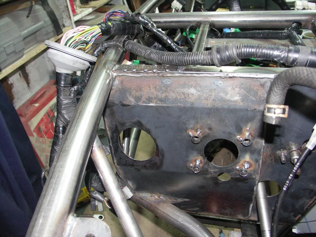 Next we fixed p clips via rivnuts to the loom that runs from the drivers side across to the rear of the engine. Routed this under the steering column. Next photo shows this and location of p clips. note the right hand p clip two is to small for the cable so just a trial fit. I've highlighted the photo to show this detail. 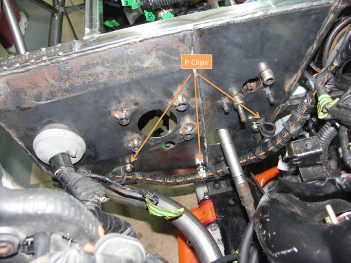 Next we turned our attention to the battery. Decided that longterm we will run with a small dry cell racing battery. Also I wanted to free up space behind the seat for storage so we went for a non standard battery position (above the gearbox). However to give some flexibility made the design suitable for a standard 063 battery. Trip to Halfords to measure one and first job was to make a simple cardboard replicar. Then fabricated a cradle to support the 'cardboard' battery. This is shown below. 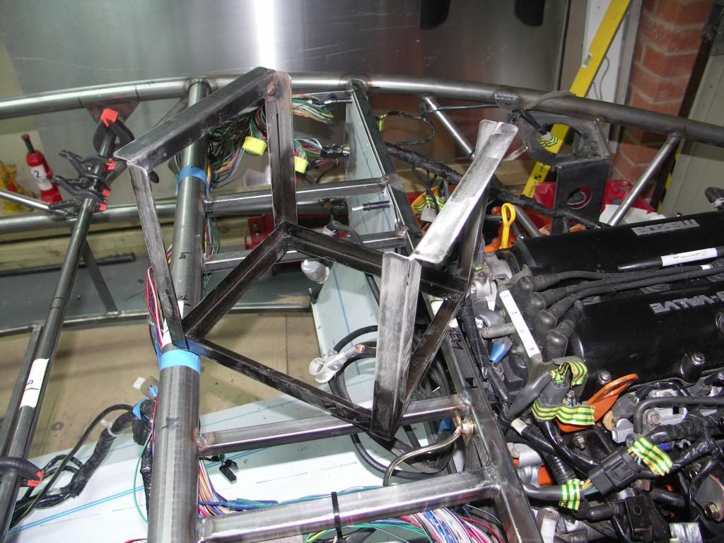 We then welded box section support bars between the bulkhead and large interior tube to support the cradle. Earthing point added via a rivnut to the MEV chassis.  Fits well. Final photo shows the battery from a different angle plus the planned loom routing for the EMU which will be positioned to the right of the battery. Again two box section bars welded in place to take the planned EMU tray (this weeks job)  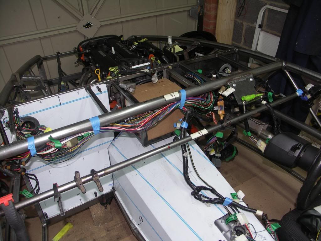 |
|
trident
Senior
   Improvise, Adapt and Overcome
Posts: 629
|
Post by trident on Apr 22, 2013 11:07:22 GMT
Great idea with the battery John.. Keep up the excellent work.
|
|
|
|
Post by scooby1929 on Apr 22, 2013 11:52:33 GMT
Hi John
For the passenger side I am doing mine exactly the same way and I think using the original mx5 gromets is a good idea. For the driver side thats a good idea drilling a new hole beside the brake servo but I am thinking of bringing mine thru on the alloy panel above the transmission cover (basically were your battery box is. I also like your idea regarding the repositioning of the battery. Very innovative.
|
|
|
|
Post by jgilbert on Apr 23, 2013 22:28:23 GMT
Tonights job was to make the EMU tray from some Ally sheet and then look to fit it. The tray took longer than expected and I ended up making a simple bottom section and separate ends pop riveted to the bottom. It needs to have some plastic trim fitted to the upturned edges at some point to prevent any cable wear. Method of fitting to the chassis was two 15mm box section bars welded in situ. All the welds so far are just 'tacks' for the time being. I plan on having a whole day fettling and welding with the chassis removed for the sub frames before it goes off to the powder coater. 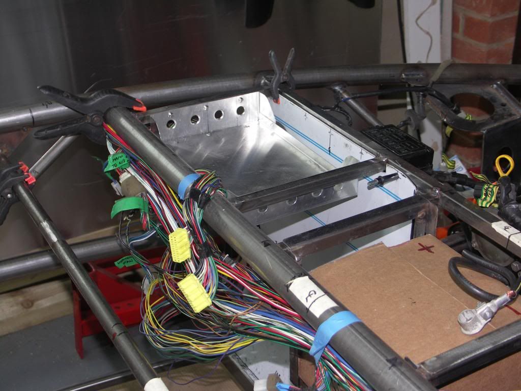 I added some swaged holes to the ends to stiffen the these parts. Used a socket with a radius on pressed on to a pipe fitting in the vice. An OK job and proper swarging tool would have been better. Next photo with the EMU in postion. 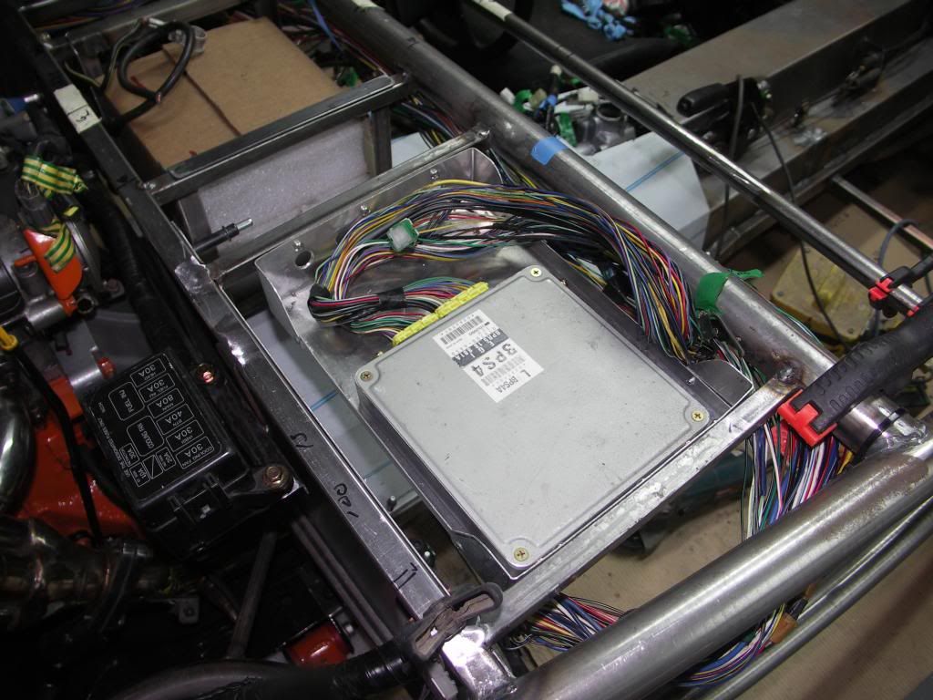 Then finished off by welding a bracket onto the bulkhead box section for the fuse box. 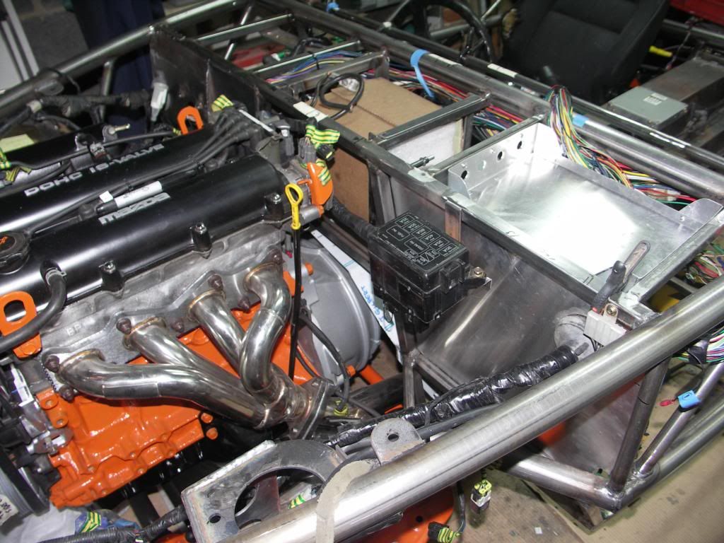 Finally, as perviously mentioned I've gone for a mid battery location with the first earthing point connected to MEV chassis. A quick check with a meger and I have good electrical continuity from the engine and rear sub frame back to this point. I intend to take the main earth cable down to a engine/gearbox bolt at some point and also to link the rear sub frame with an earth cable to the PPF. |
|
|
|
Post by jgilbert on Apr 28, 2013 21:43:29 GMT
Getting to be a normal Sunday. Garage, photos then Forum update. Todays little job was to mount the radiator. Used Scooby's idea of drilling the frame and welding some tube for the top radiator brackets. Nice day meant the garage door was open for a change. Radiator mounted. 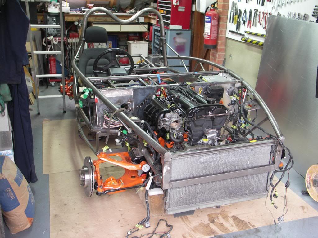 Better photo of the EMU tray and fuse box. Carbon sheet next to it is self made and is designed for the bottom of the battery tray. 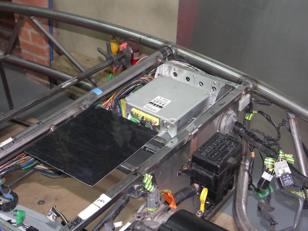 |
|
|
|
Post by jgilbert on Apr 29, 2013 20:44:02 GMT
Ok a bit more to report. The carbon fibre sheet in the last post was a clue. So we now have a dashboard. Made from actual Carbon Fibre  For the full story read on.  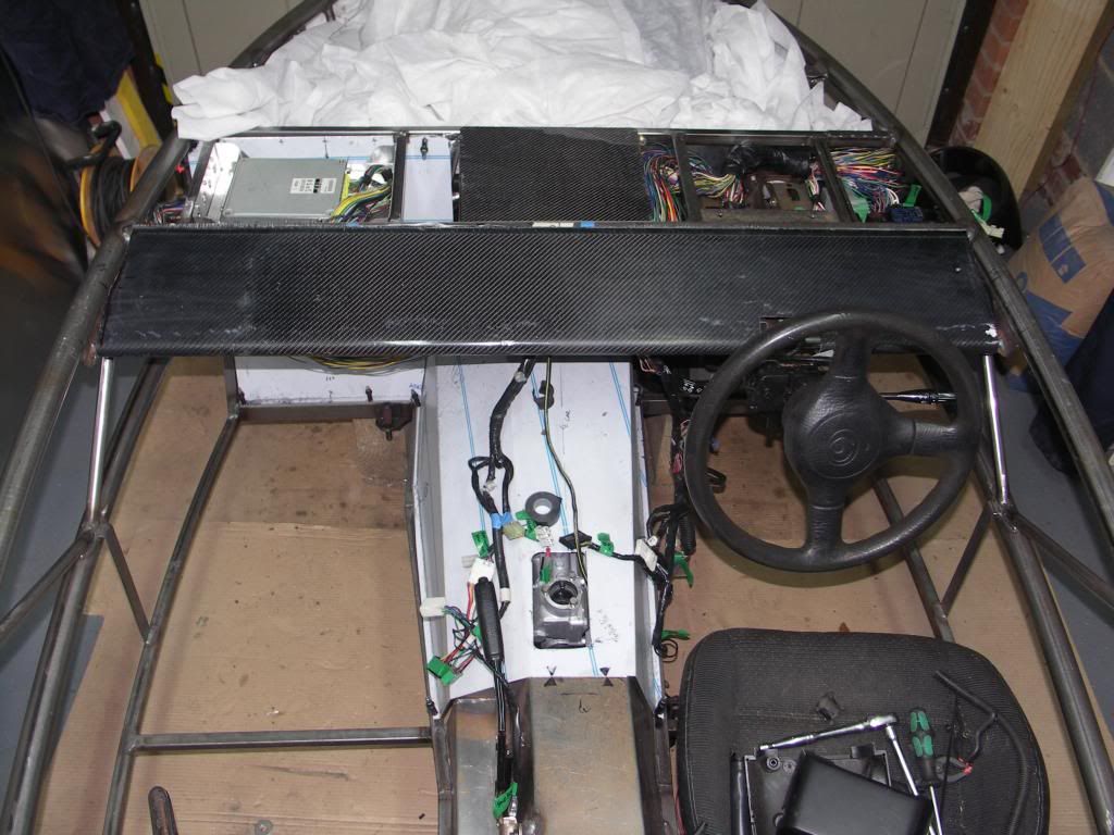 Our plan has always been to add a dash/facia board to the front of the cockpit. Hence the additional tube welded to the chassis above the steering wheel you may have seen in previous posts. The process began with making a mould. We used Contiboard and a section of 40mm dia plastic pipe to form the bottom edge radius. This complys with the IVA requirements. The mould ended up looking like this. 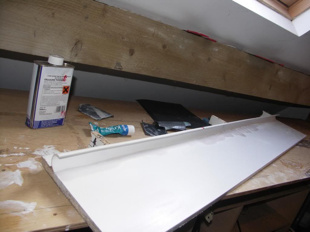 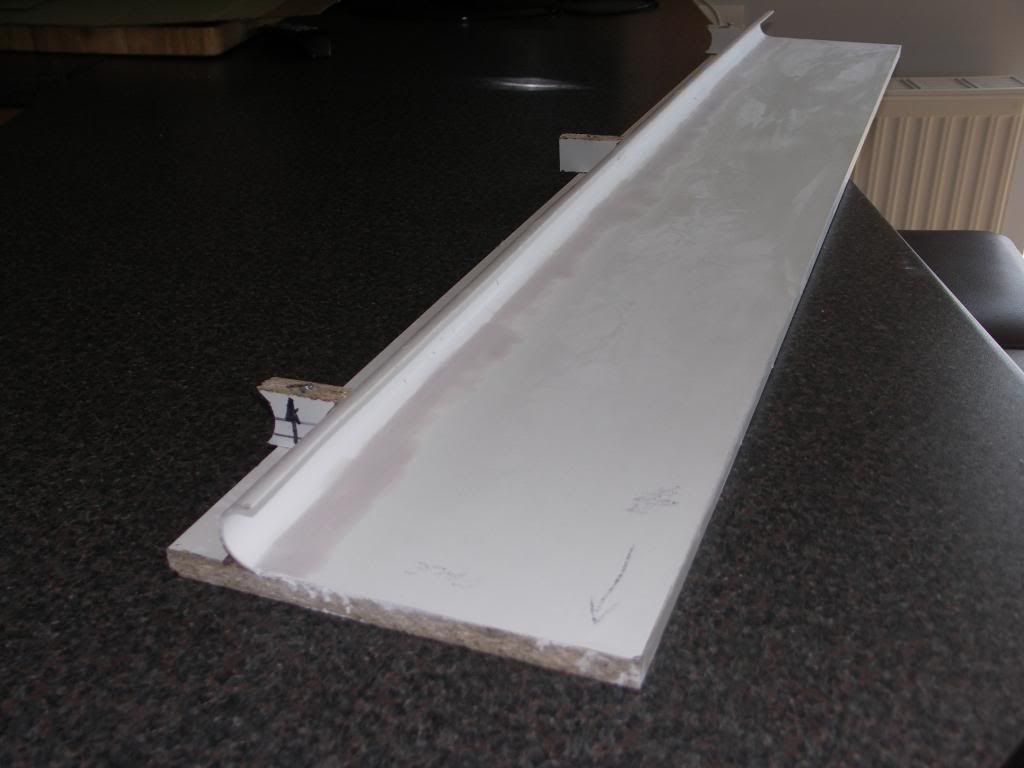 A few nights of research on the web on hand laminating CF and a after a fairly costly order, our CF matting arrived. Together with release agents, polyester gel coat, and epoxy laminating resin. Over the weekend we experimented with some flat sheets, hence the battery tray bottom in our previous post. Sunday was D day and having polished the mould we went for it, this isn't cheap stuff to muck up!  Wish my dad had this much fun with me ! It was bordering on solvent abuse ! honest my eyes don't normally look like this. 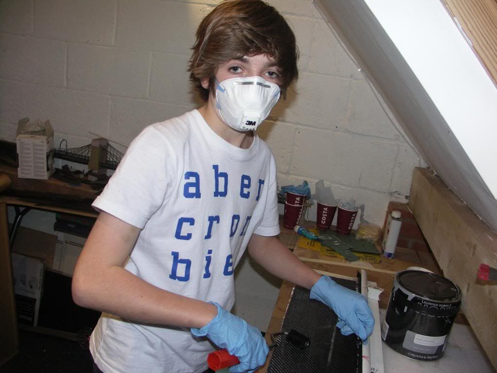 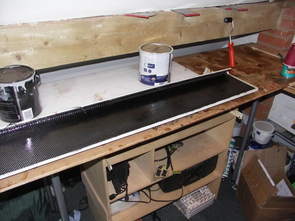 Then tonight the moment of truth ! would the part release from the mould. Thankfully yes. Little bit of trimming and a trial fit together with the battery box cover (again CF). 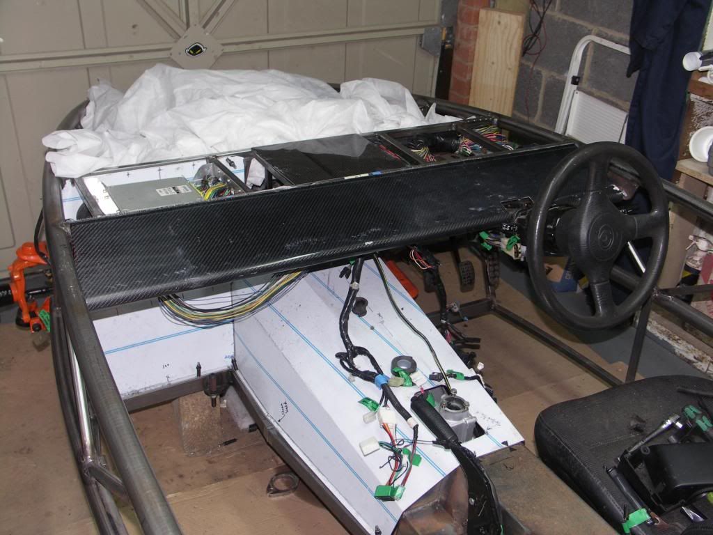 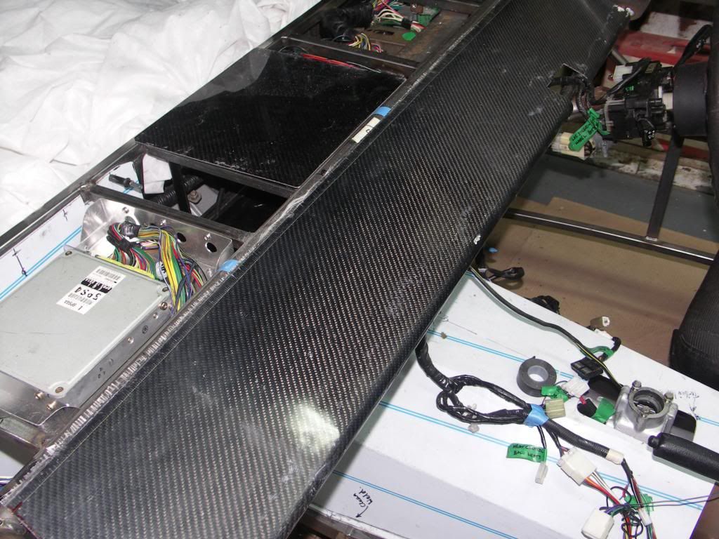 Its incredibly light yet rigid. The surface finish does need a good flat and polish to get the full shine. There are a couple of defects in the surface that I need to sort but otherwise a very interesting process and we think a different look. Next job is to trim the top edge once we have our bonnet and then secure it and plan how the instrument pod will fit. |
|
|
|
Post by tom on Apr 29, 2013 21:52:23 GMT
Some really nice features there. This is going to be one very nice Exocet!
|
|
|
|
Post by jgilbert on May 11, 2013 22:02:54 GMT
Spend last night reviewing how others have supported the bottom of the radiator. For the top mounts, I copied Scooby's idea of cutting and welding two sections of tube into the frame and bolting the rad using the standard rubber washers. This effectively holds the rad in place requiring some method to support the bottom of the rad. Everyone seems to have a different method for the bottom. For my design, I deciding to used the Mazda bottom radiator rubber mounting pins that are on the rad as standard. I couldn't see this idea when searching. Most people seem to have used the roll bar mounts and fabricated brakets that attach there and then bolt to the rad. My design meant making two simple brackets out of flat bar. Bent at the bottom to accept the rubber mounts. Photos below.  and with the rubber mounting in postion. 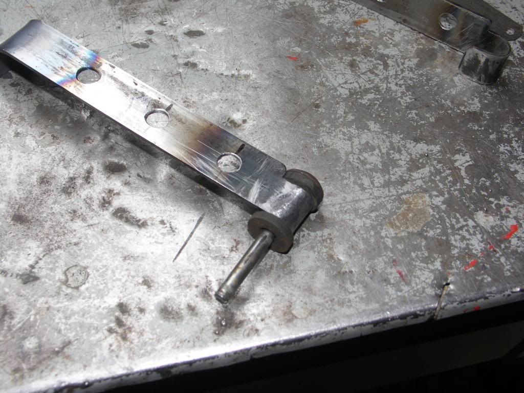 Simple job to then weld the brackets to the frame.  Finished off by mounting the horns via the top rad bolts to save making separate horn brackets and fixing points. 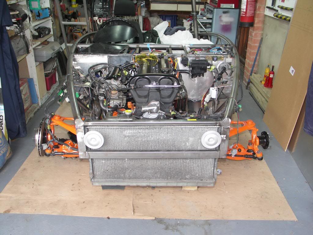 |
|
|
|
Post by jgilbert on May 13, 2013 21:37:03 GMT
Hi Team, Spent Sunday sorting our the steering wheel column/bulkhead shroud. Its not an obvious fit as the Exocet bulkhead is stepped where as the Mazda bulkhead is flat where the column passes through. I decided to have a go at fitting both the rubber column seal and the universal joint plastic shroud. I don't think this is essential as squelch's Exocet passed its IVA without the shroud. Defiantly a bit OCD, but its only time! and it was raining so I had an excuse for not cutting the grass. So I started by reviewing my donor photos. This shows the original configuration nicely and orientation of the fixings. 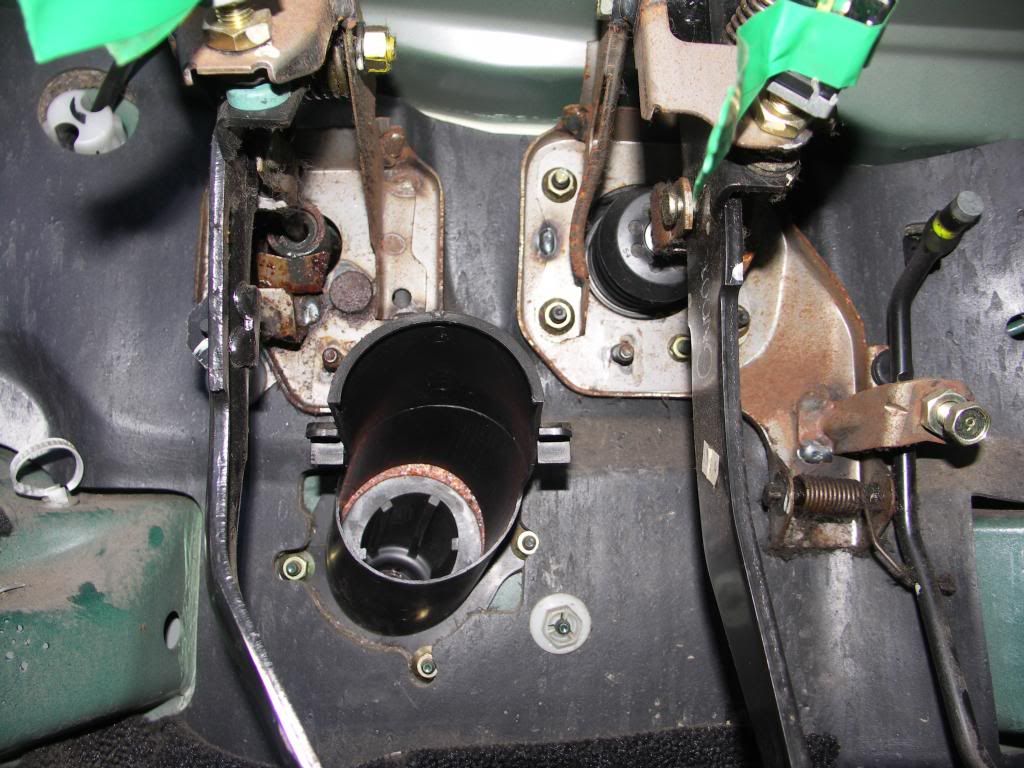 First decision was to decide to fit both the rubber seal and shroud from the inside of the car. On the Mazda the rubber seal is on the engine side of the bulkhead. But as previously stated the 'step' in the Exocet bulkhead rules out this method. I had to open up the bulkhead hole in order for the rubber seal to pass through without it been squeezed to tightly. The hole enlargement wasn't the easiest of jobs and didn't end up that neat a job. Luckily it dosen't show. Next job was to split the column into two sections, this made the fitting removal and refitting process so much easier. Photo shows the lower column section with the rubber seal in position.  Next I fitted the lower section of the column with the rubber seal in place and marked the approximate position of the seal mounting plate and holes. The two holes on the flat section of the bulkhead were drilled and rivnuts fitted. The third fixing required a spacer bracket and rivnut, as shown below.  Column and rubber seal in position. 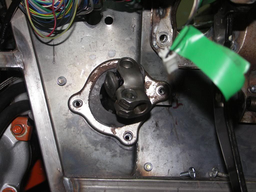 Now, as the position of the bulkhead is different from the donor this required about 20mm cutting off the end of the plastic shroud in order for this to fit. I just cut back to the lugs that are used to 'snap' both parts together. 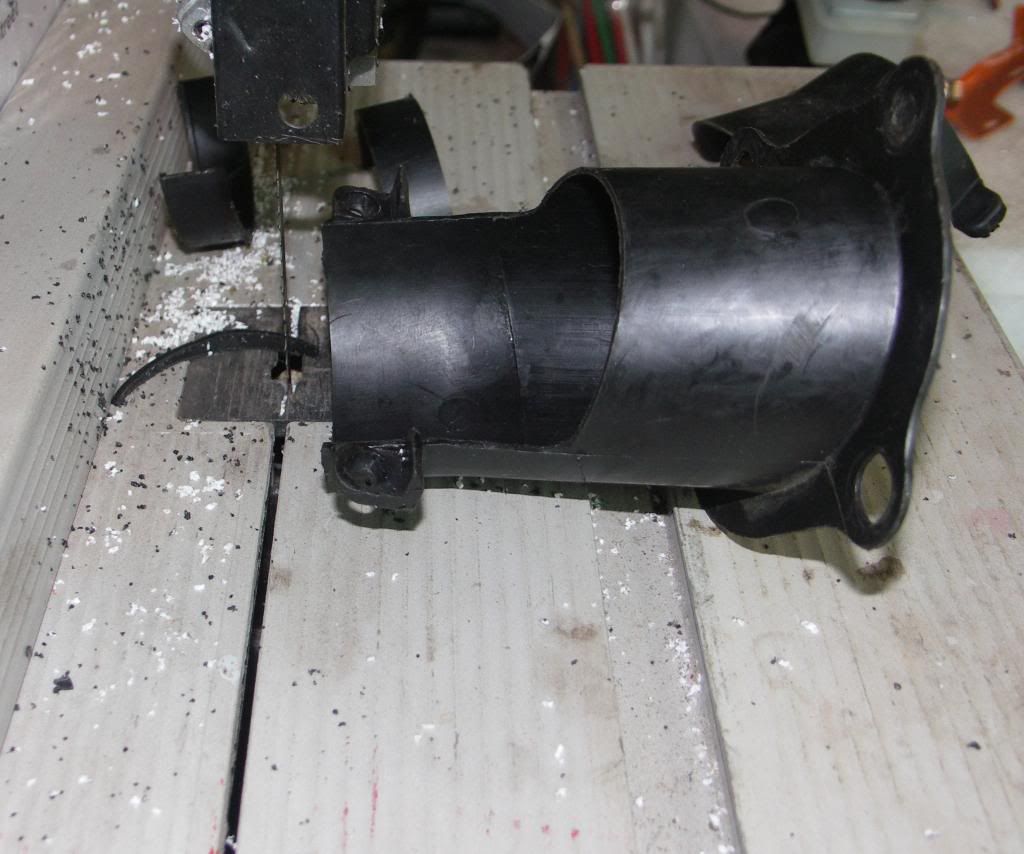 Whole lot then bolted up to the bulkhead with the top section of the column reconnected. Next photo shows the finished job looking up from the floor with the plastic shroud in position covering the universal joint. 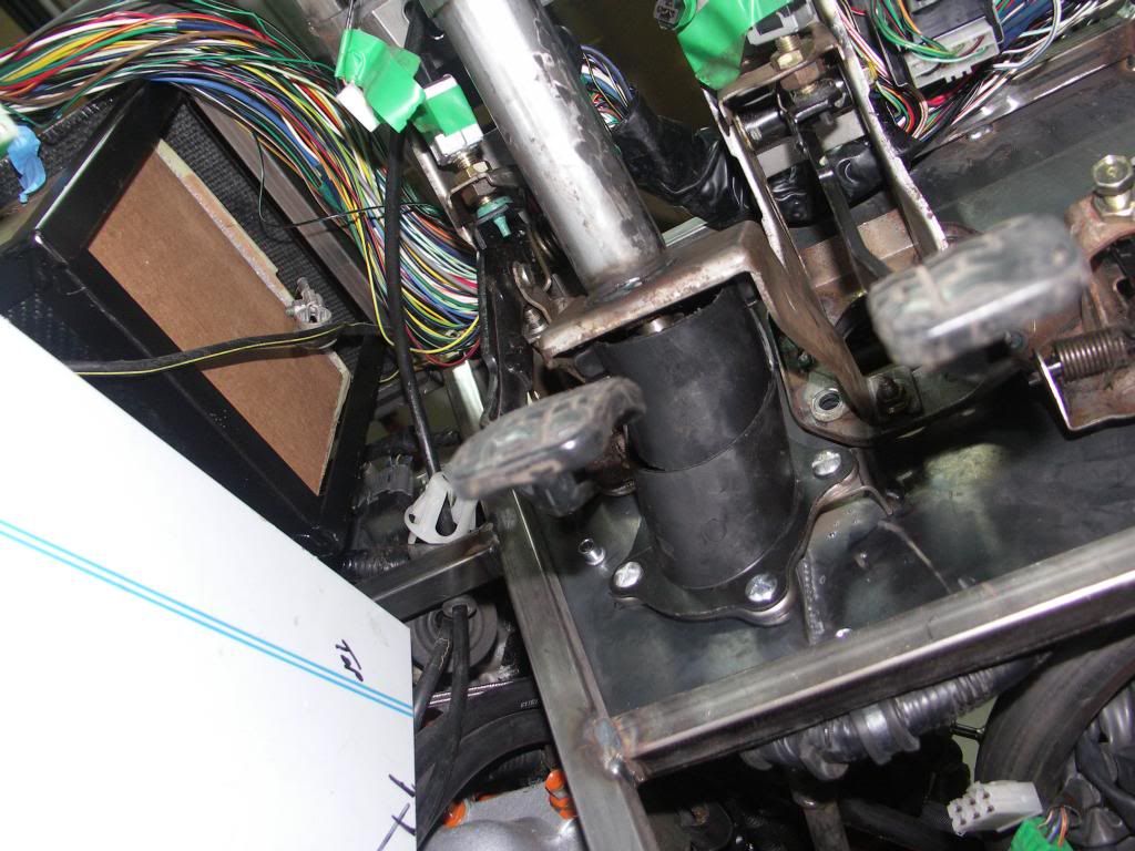 Probably, never going to be seen so defiant overkill, but at least we know its done. This may help others should anyone feel the need to follow. |
|
|
|
Post by scooby1929 on May 13, 2013 21:54:06 GMT
Nice work as usual John.
|
|
trident
Senior
   Improvise, Adapt and Overcome
Posts: 629
|
Post by trident on May 14, 2013 12:57:33 GMT
John did you find that the steering column was off to one side as it went through the original bulkhead hole? I've got to open out my steering column hole as well as the column is nearly rubbing at the 7 o'clock point as you view the hole from inside the car. An that's without any rubber seal.
|
|
|
|
Post by jgilbert on May 14, 2013 23:05:24 GMT
Chris, mine isn't to bad. It's not perfectly central but not close enough to rub anywhere. I would definitely split the steering column into the lower and top section. Its heavy and awkward otherwise. It splits easily at the middle U/J as this is situated inside the donor it should be rust free. One bolt. I'm guessing its a high tensile bolt so don't lose it.
I also spent 10 minutes carefully cleaning the bottom column spline that fits to the steering with a needle file. As this is open to the environment, it does become rusty and can be problematic to fit. 10 minutes cleaning and then a bit of grease makes all the difference.
Then you can concentrate on getting the bottom section fitted and check for any rubbing. Once your happy reconnect the top section tighten the bolt to 14-19lbf.
Enjoy.
|
|
|
|
Post by jgilbert on May 21, 2013 21:41:11 GMT
In a previous post (actually at the top of this page) I had written about how I had used the original Mazda loom grommets on both the Left and Right hand side of the bulkhead. Unfortunately, I Cocked Up on the Right hand side (drivers side)!!!!!!!!! This is what I had done. 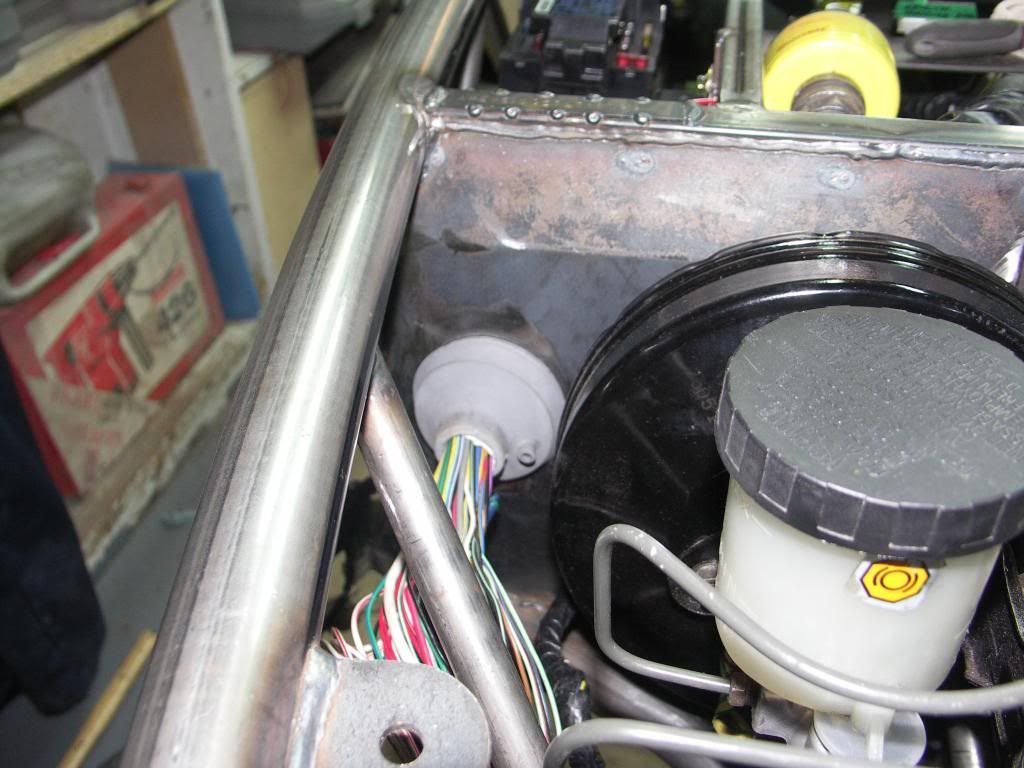 I couldn't see a problem, until I looked at where the throttle cable needs to pass through the bulkhead. I managed to position the grommet right where the cable needs to pass through the bulkhead. See the next picture. 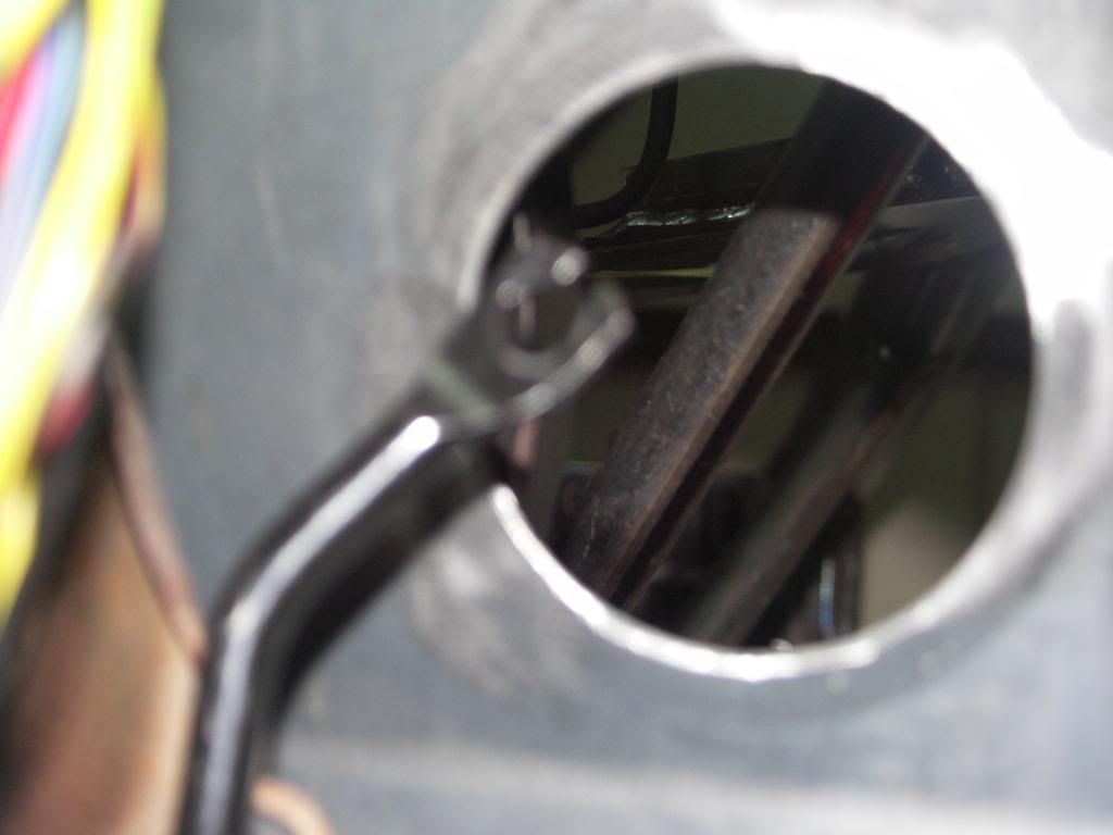 So for a solution, I wanted to use the grommets if possible, as It looks right and is an effective way of passing the cable through the bulkhead. I think other's may have got around this problem by passed the loom back over the top of the pedals and then passing it through to the engine bay above the gearbox. Nothing wrong with this, but I had already planned the route coming out on the right by the servo. So the answer was to re-thread the loom back through the bulkhead. I then cut a new 70mm hole higher and to the right of the first hole. I also cut a 70mm dia plate and tack welded this into the original hole to blank it off (will fully weld once the chasss is removed prior to powder coating). So this is what it now looks like. 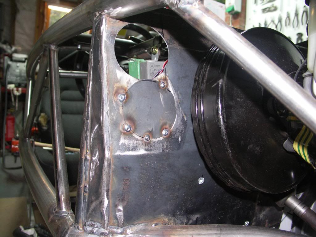 and from the inside. With the grommet up high this leave plenty of room to position the throttle cable.  Last photo from the engine bay side. Note, having read about bcantor7's IVA fail on his VIN plate not being fully welded, looks like I also have a similar issue to address. 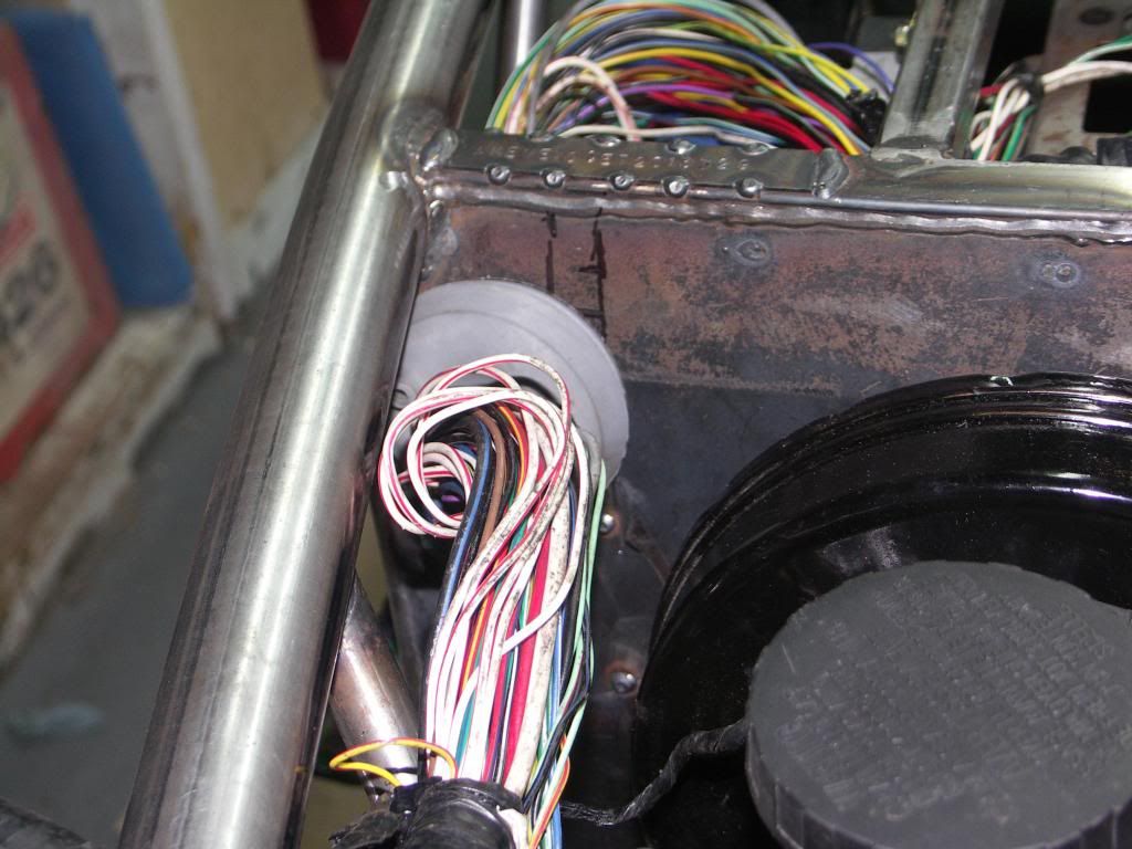 |
|
|
|
Post by jgilbert on Jun 11, 2013 21:13:11 GMT
Not much build time recently, however have taken the opportunity to mount the water system expansion reservoir. We went with the standard front passenger side mounting position. This involved making three brackets to ensure the reservoir was securely supported. We also had to bare in mind the need to make the brackets removable so the radiator could be easily removed if needed. For the bottom bracket, decided that we would modify the lower water system pipe bracket. I'd already welded a mounting plate for this on the chassis so this was a logical addition. 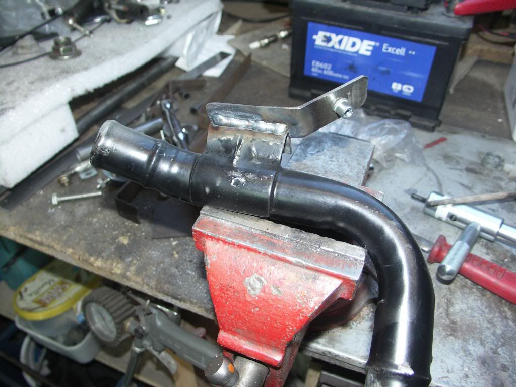 Next the top two brackets were 'rivnuted' to the front chassis. With rivnut fittings for the reservoir. Next photo shows all three brackets in location. Then a simple job to bolt the reservoir in place. Final photo. 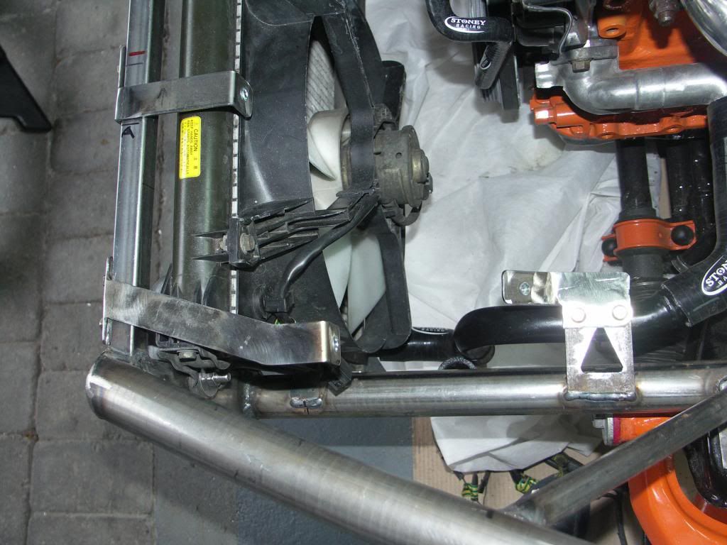  One important point to note, clearance is tight between the standard air inlet pipe and the reservoir. I ended up with about 10mm clearance but it would have been easy to miss this and end up with parts rubbing. |
|
trident
Senior
   Improvise, Adapt and Overcome
Posts: 629
|
Post by trident on Jun 11, 2013 21:35:30 GMT
Welding brackets on will make it look first class once you have it painted or powder coated. As always nice work mate.
|
|


