|
|
Post by jgilbert on Feb 11, 2014 19:10:01 GMT
Another vent on the other side to even up the look? Trident, yes was thinking that also however, the one sidedness is growing on me. The passenger side is where the heat is, due to the exhaust. Will have to see. Maybe less is more! |
|
|
|
Post by gwnwar on Feb 11, 2014 22:30:37 GMT
I vote for only one..(nice job on install).. It looks like it has a reason to be there. Two would be more rice looking..
|
|
|
|
Post by jgilbert on Mar 1, 2014 23:07:48 GMT
Slow progress at the moment due to not having enough spare time. We have therefore been forced to concentrate on finishing off small jobs. The first of these being the rear fixings for the rear cover. As we have got a floor pan under the petrol tank I decided to use this as a fixing point. I replicated the plate that is at the rear passenger corner of the chassis by adding an identical plate to the drivers side. I then made two simple brackets with rivnets which will be fibre glassed to the inside of the rear cover. I can then bolt through the plates and floor pan and secure the rear cover in place. Photo of rear cover and the brackets. 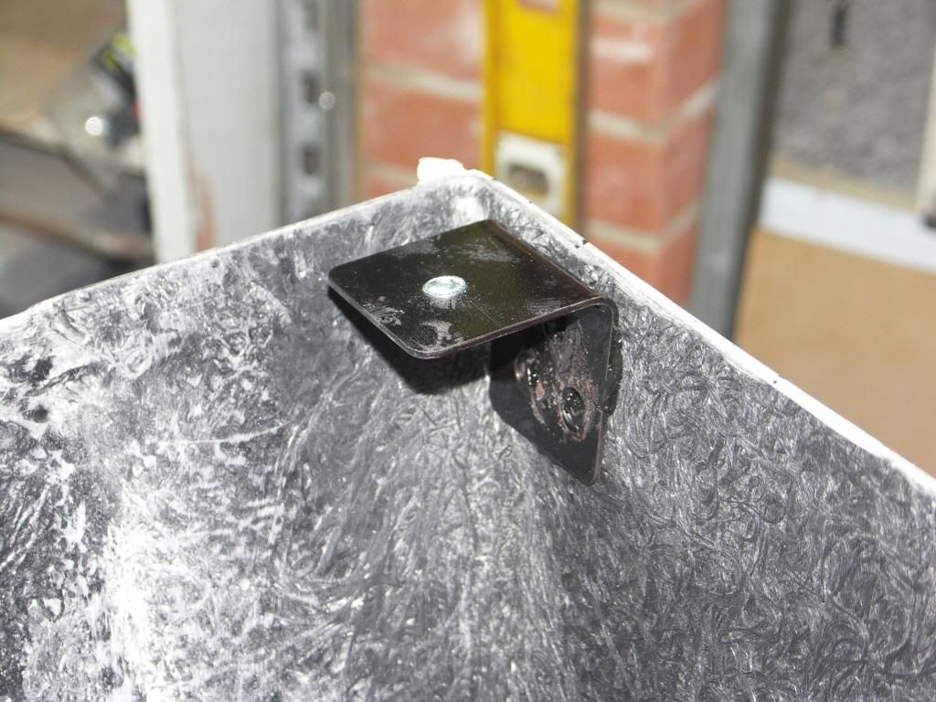 And a picture of the floor pan where it will bolt through. 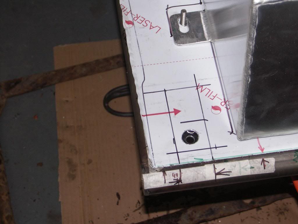 So back to the contre console. Side infill panels, couple of hours of template making for the three side panels. Not sure if I should make these in carbon fibre or aluminium? 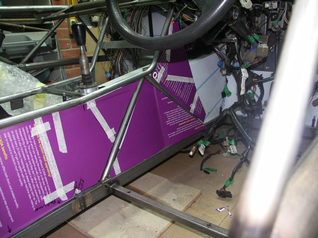 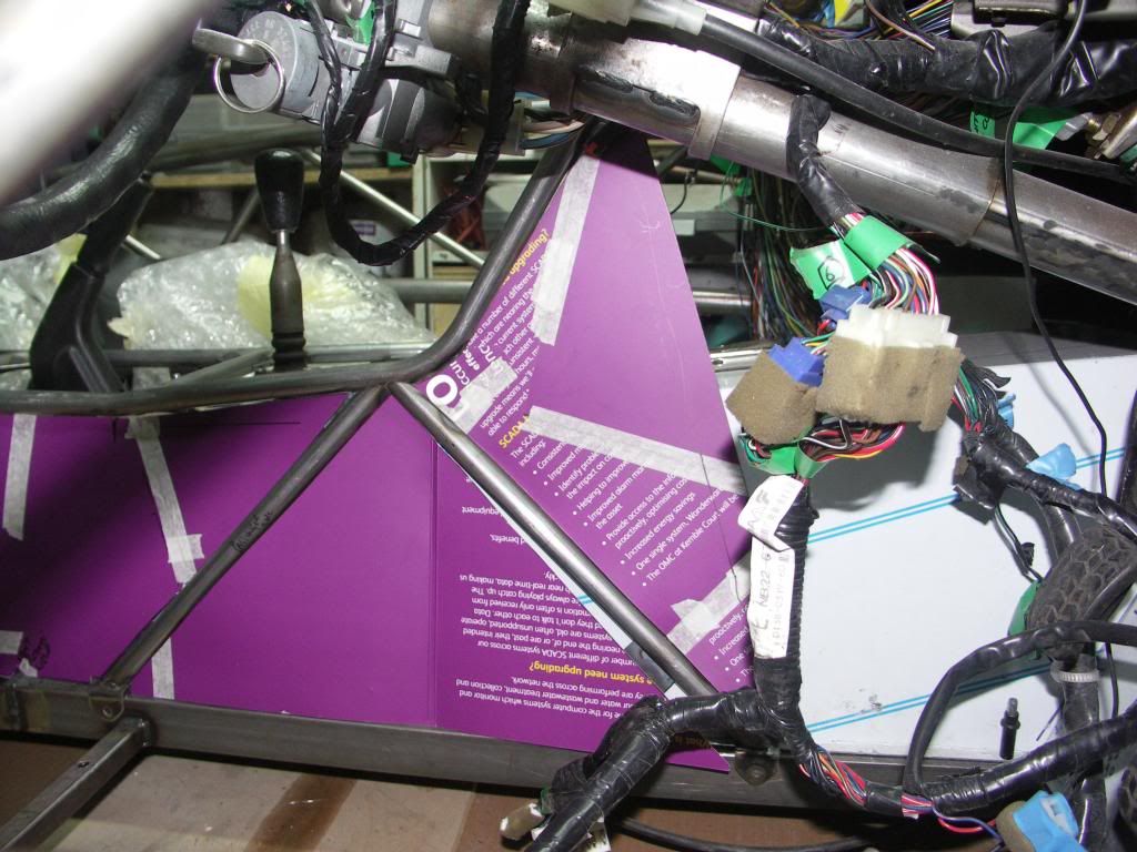 Then today managed to get some brushed stainless steel sheet rolled to the same profile as the console for the main top infill panel. Halfway through I decided that a carbon infill panel for switches would look good. so added a cut out. Not sure I like this, but I have invested 4 hrs work so it may have to stay for the time being. 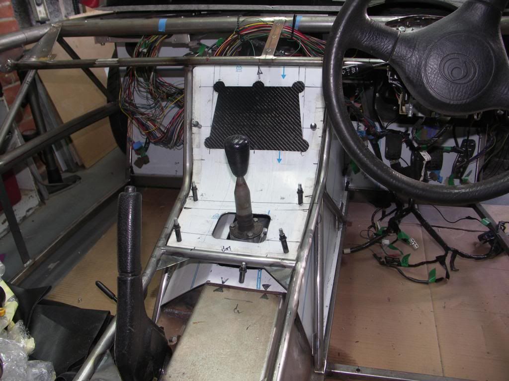 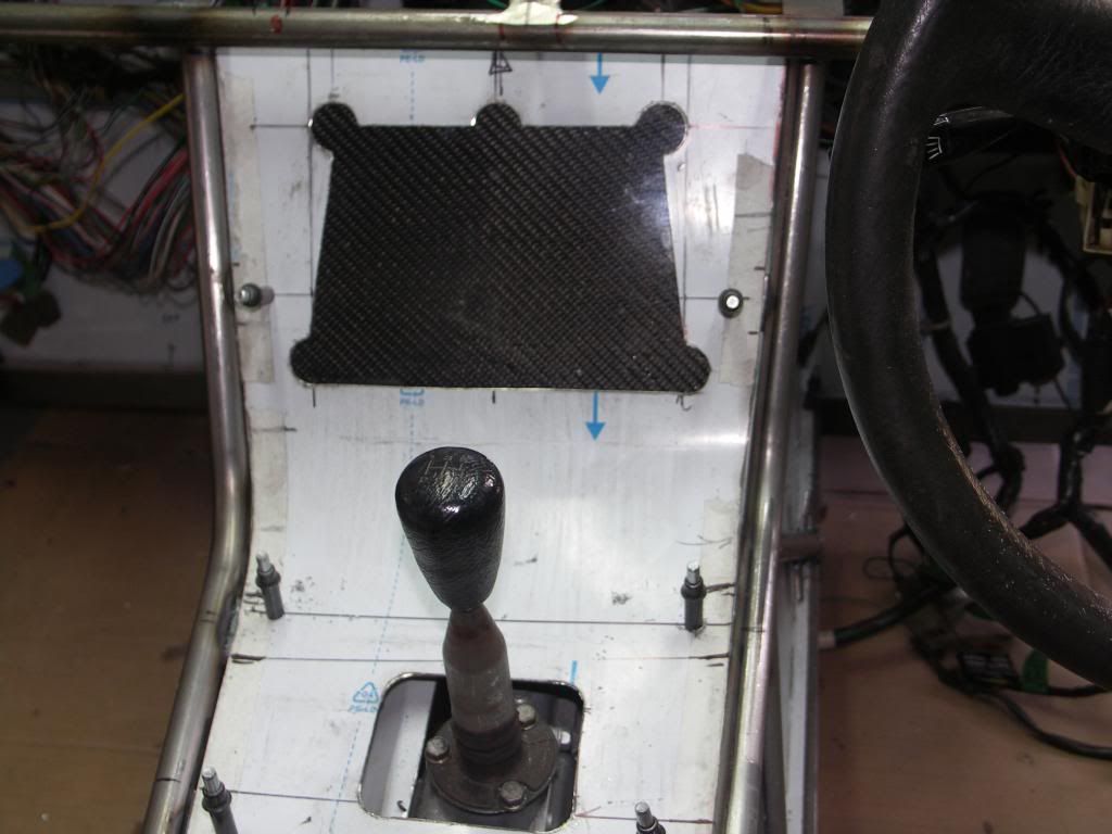 |
|
|
|
Post by jgilbert on Mar 8, 2014 20:11:05 GMT
So not happy with the 'Mikey Mouse ears shapes' of the cut out on my centre console I trimmed the sides to get rid of the original taper. We like this better, the plan is to have some nice stainless domed head allen screws in the carbon where the cut out radius' are. The beauty of the carbon panel is we can change the switch layout later (maybe a boost gauge later?) if we want without having to remake the curved panel which is time consuming. This is the latest look, 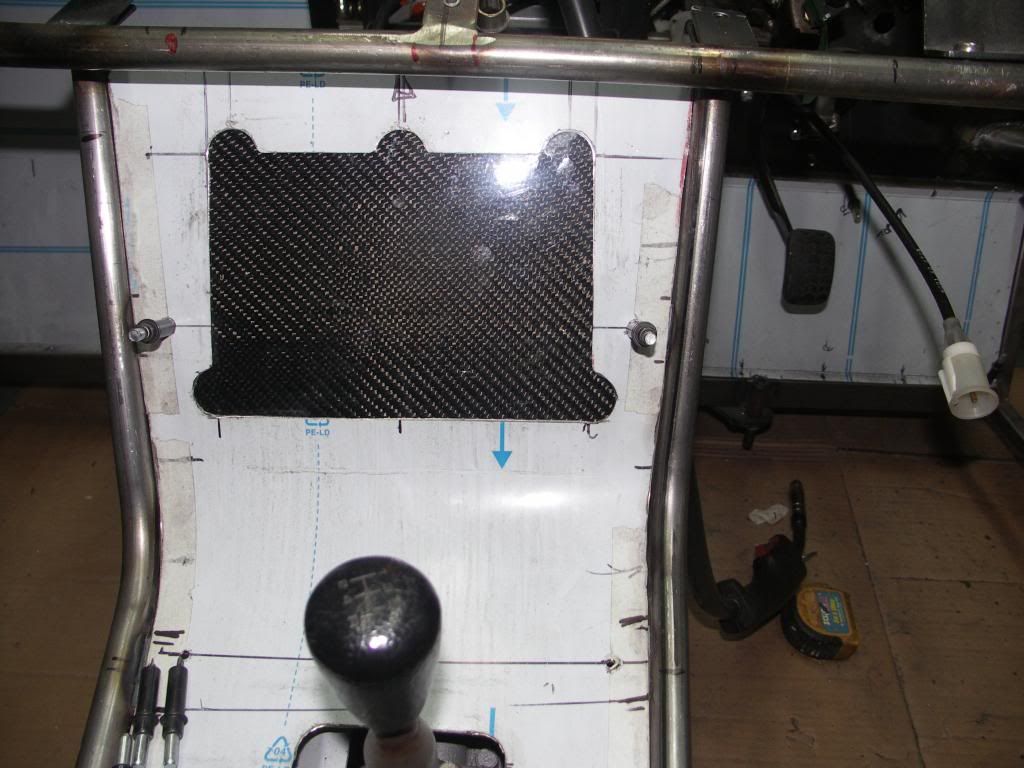 Then we started the strip down to get ready for the powder coating. Loom and steering column removed. Looks really bear. 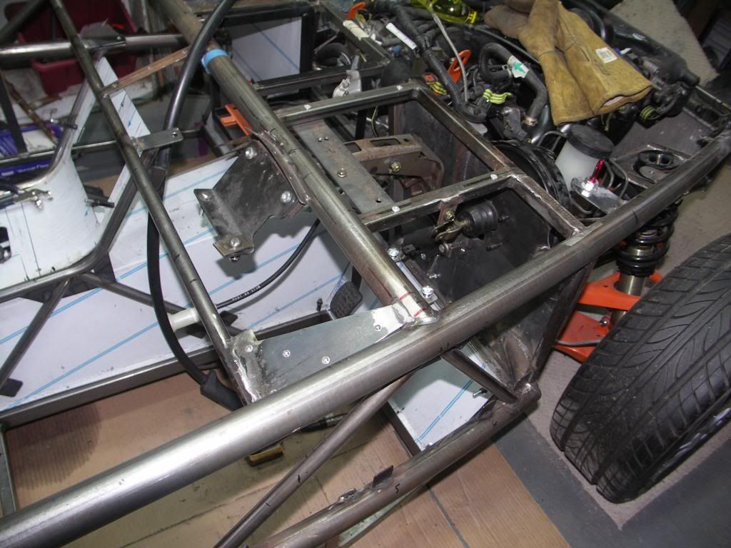 With the wiring out the way this allowed us to weld some tabs to the front two open sections of the chassis side. These will have carbon panels made and screwed to the tabs to infill the space. 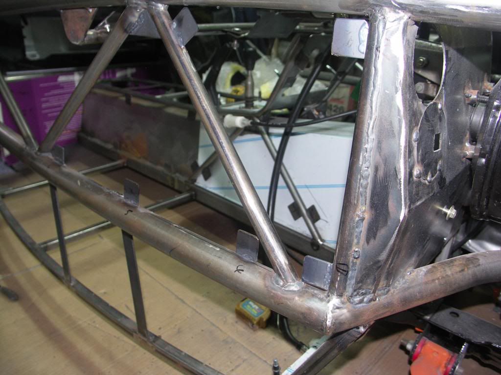 I also cut the bottom horizontal bars than run from the bottom of the chassis to the mid tube. These was re welded but without the offset towards the inside of the car. The reason for this is that I'm using carbon side panels and these are only 2 mm thick, also much lighter that the standard plastic sides. You can also see in the picture above where we added an additional horizontal bar between the front and original first bar. One side done, one to go. Getting there slowly. |
|
|
|
Post by jgilbert on Mar 9, 2014 19:36:15 GMT
Great to see the sun shining today! Opportunity to cross off another small job. Previously, I had noticed that the front wing stay rubbed on the top of the upper wish. Only enough to take off the powder coating but not right. So this morning I decided to sort out the problem. First photo shows where it had rubbed the powder coating away. Apologies for the dust on everything, big cleaning job on the cards when the chassis is off. 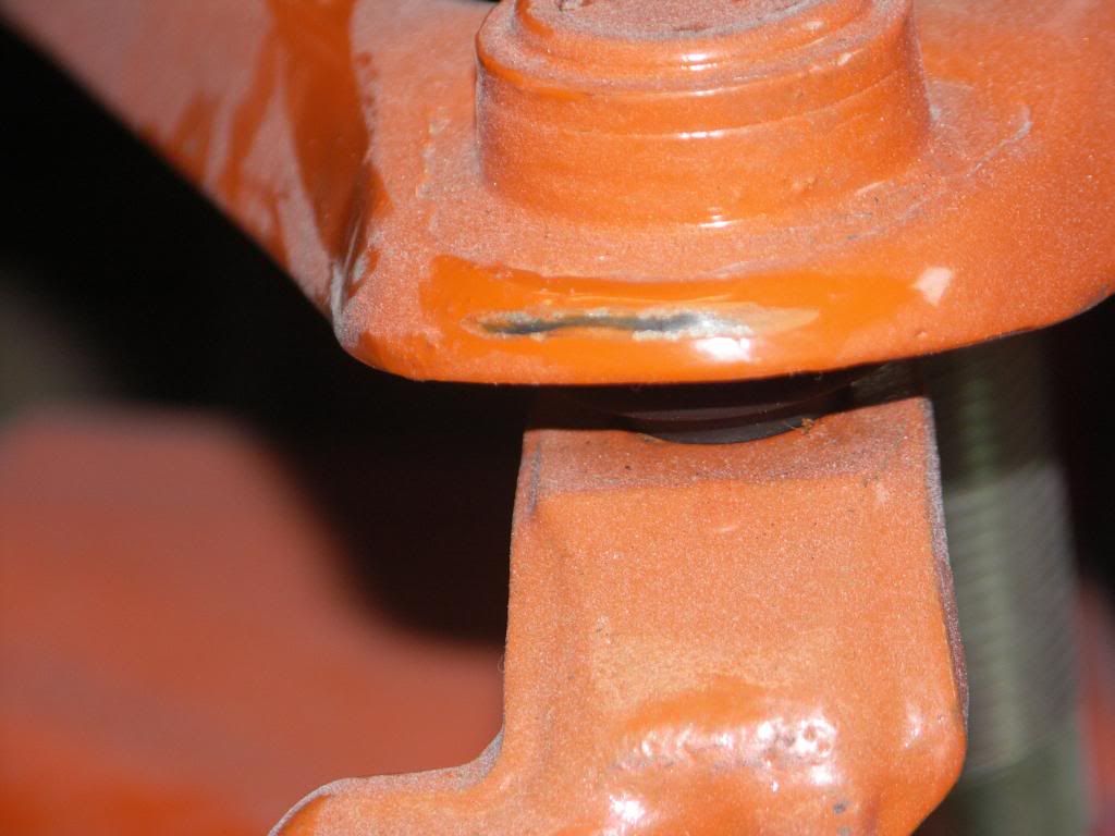 In fairness it could be where I modified the wishbones to take out the edges that need trim added. So before I modified the stay I made a simple template to ensure the geometry of the stay was maintained. Card and two punched holes for the top of the stay and a sharpie pen to draw around the hub location plate. 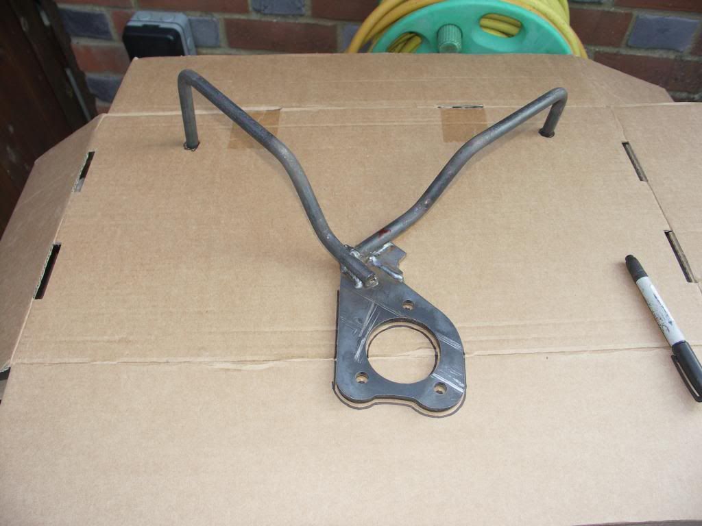 Confident I had a pattern to refer back to I sent about cutting the stay in order to lift it away from the wishbone. The the plan being to insert a small 15mm extension to lift up the stay away from the wishbone. 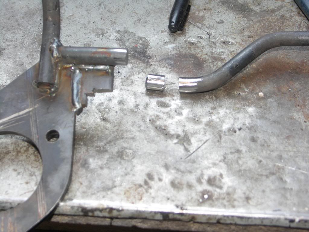 I ground out a vee in each piece in order to get the necessary weld penetration. Having added a15mm extension to the lower section I needed to remove the same sized piece from the upper section of the stay to maintain the stay length. Tacked all this together and tried it against the template we made. Last two photos show the modified stay in the template and on the car with the additional clearance between the wishbone and stay. Thought I would post this in case others had a similar issue. 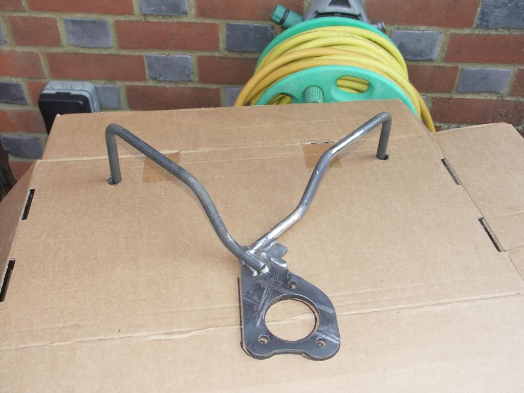 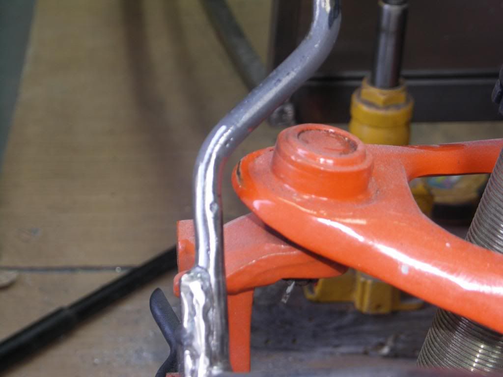 |
|
|
|
Post by gnc on Mar 11, 2014 19:26:10 GMT
Are you going to use the abs? If so, it looks like a cutout / hole will be needed for the sensor.
|
|
|
|
Post by jgilbert on Mar 11, 2014 20:40:09 GMT
Thanks for the question. No ABS on our donor. How's your build going. Missing updates from the Green Demon!
|
|
|
|
Post by gnc on Mar 11, 2014 21:12:48 GMT
It's been a long time since we were anywhere near the factory, it's been one weekend at work after another. Have got a few parts on order though so should be back at it soon hopefully!
|
|
|
|
Post by jgilbert on Mar 15, 2014 18:59:31 GMT
Another job crossed off the list today. When we first assembled the chassis onto the PPF/subframes, the rear 'tab' that is welded at the back of the 'thing pit' didn't line up with the rear subframe. I don't think is is an uncommon problem. Trying to get it to fit would have meant damaging the subframe coating so we hacksawed both tabs off. Unhappy that this had removed a fixing point between the chassis and the sub frame I wanted to reinstate this connection but in a way that meant I wouldn't damage the subframe coating and chassis once its coated. So I decided to modify the tubular braces that link the under side of the rear chassis together. First off I made two 'L' shaped brackets out of 6mm plate. 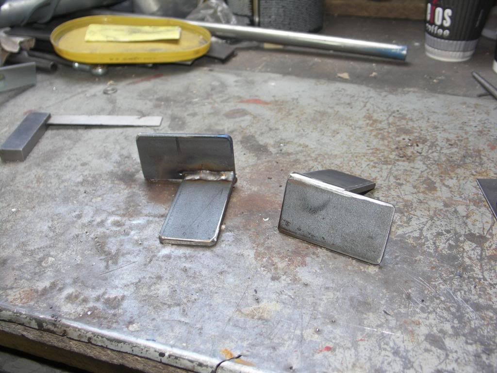 Next job was to offer these up to the chassis and drill them so that I could fix the bracket onto the chassis. For additional strength I plan to weld in a tube where I drilled the chassis. You can see this in the next photo. Its set up for a 12mm dia bolt. 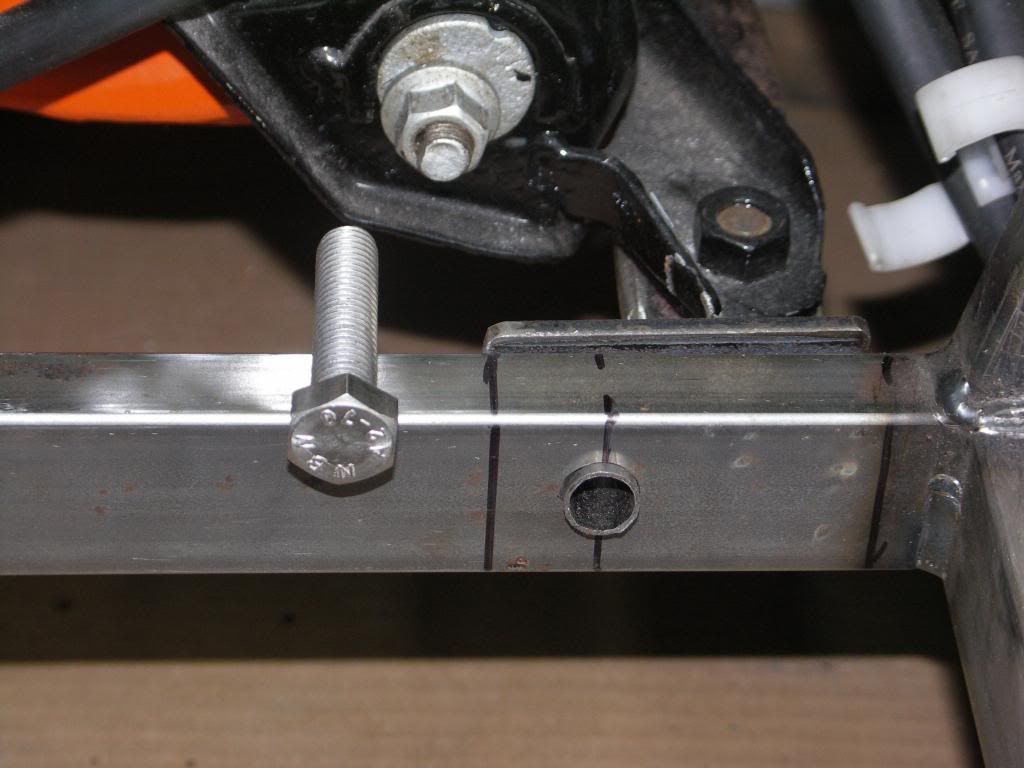 With everything in position I marked where the bracket met the subframe tubular braces. I then welded the brace and my new bracket together so that I ended up with a one piece brace/ bracket that uses the existing subframe mounting holes and the new holes I have drilled in the chassis to 'link' everything together. The nice thing is its all removal without damaging any of the coated surfaces. The braces will be coated when the chassis is done. Couple of photos to explain. 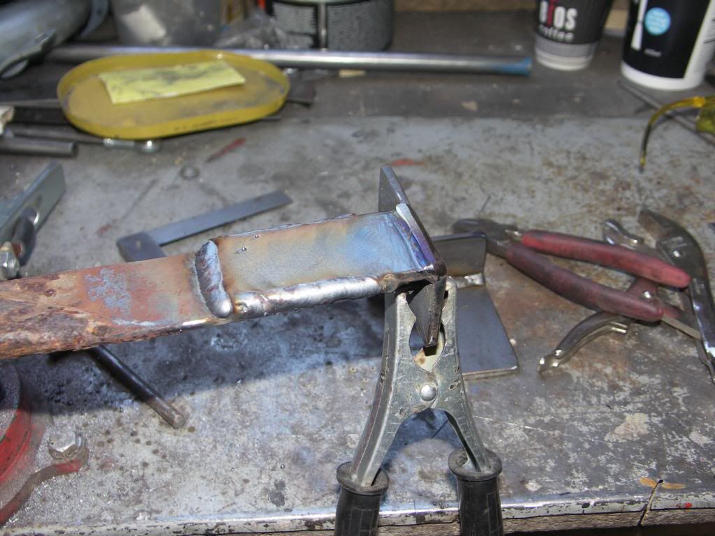 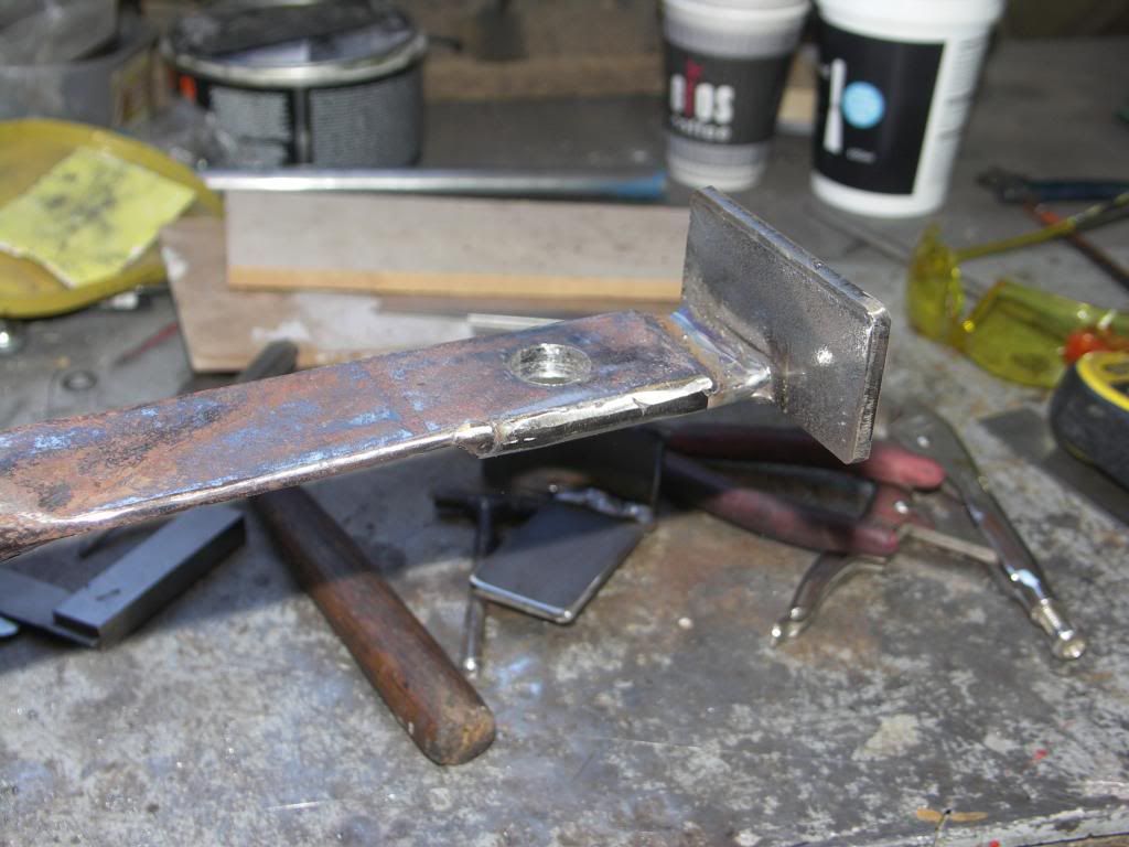 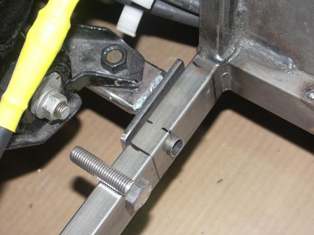 |
|
|
|
Post by scooby1929 on Mar 15, 2014 20:36:16 GMT
John I dont know why Mev just dont leaves those tabs blank then you can just drill the hole yourself in the correct position. I had to fix mine to
|
|
|
|
Post by jgilbert on Mar 16, 2014 1:07:14 GMT
Scooby, I'm guessing there must be massive tolerances in the original MX5 assembly. Therefore getting the kit to fit will always be a a matter of trial and error. I agree the rear tab seems to be a problem area. I've posted my take on it only so someone else might be able to improve on my solution. Having payed out (and this is not a criticism) for a nice shinny kit and to find it doesn't fit in this area is a bit of a 'deep breath' moment. So hopefully if your in this position I've presented an alternative option. My solution is only my answer to the problem, others will have a better approach. At the end of the day its great that we can all add our own perpective to a problem and learn  . |
|
Deleted
Deleted Member
Posts: 0
|
Post by Deleted on Mar 18, 2014 11:35:43 GMT
Hi Everyone, over a month since we last updated our thread  Holidays and Triathlons seem to have got in the way. Anyway, I have finally picked up my bodywork and seats so plenty to think about and do over the next few months. I also purchased my shocks, going for GAZ coil overs with custom spring ratings. Um'd and ar'd about what shocks to get but decided that they will be crucial to the handling and the feel of the car so I bit the bullet and when for the more expensive option which I'm sure will work out fine. 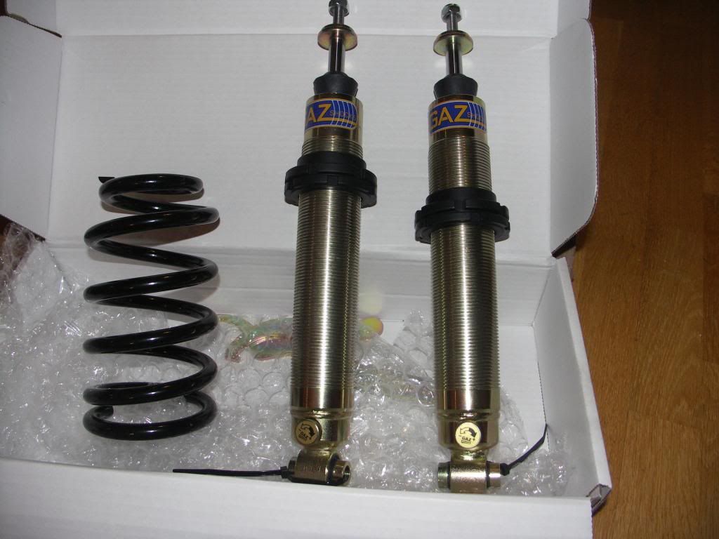 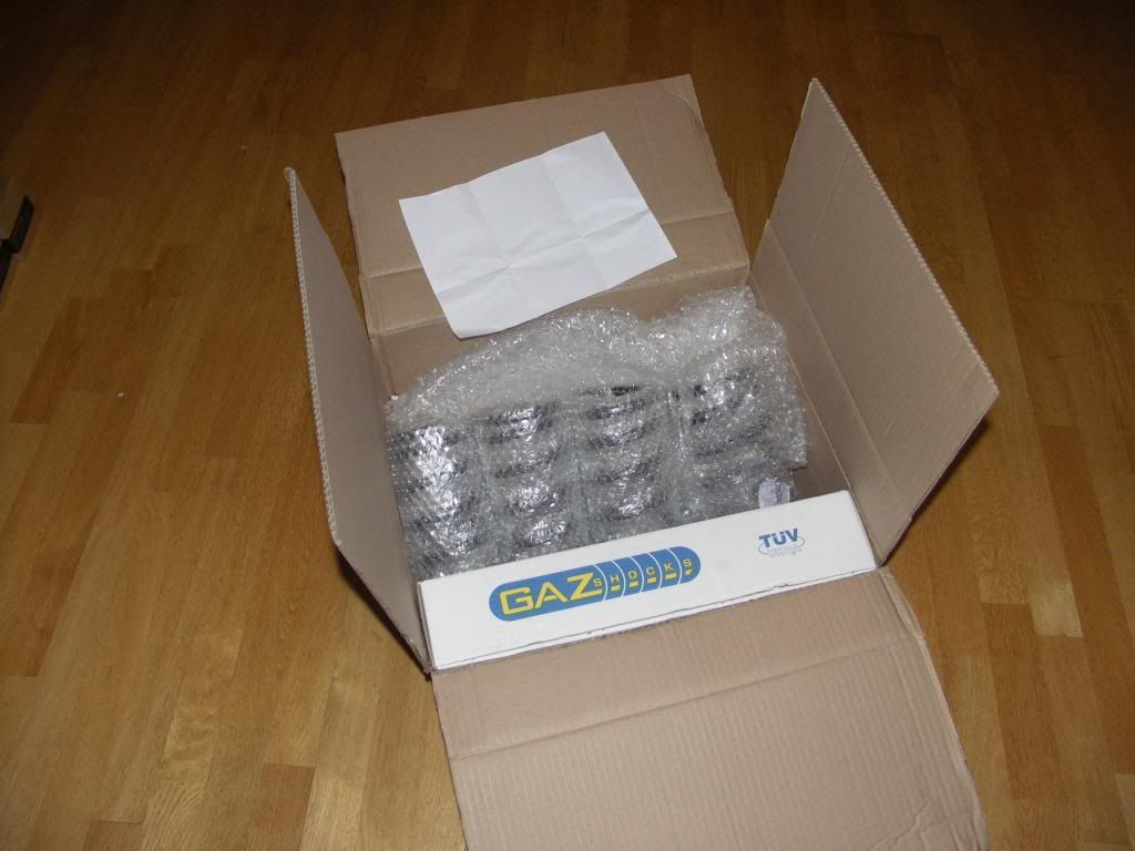 So straight out to the garage to fit. 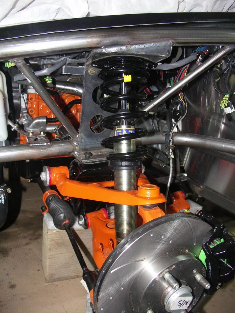 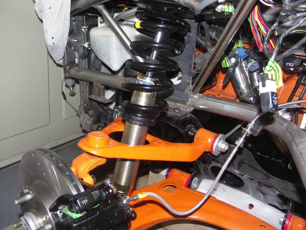 Next job was to think about how to mount the seats. I didn't want to drill through the seat so decided I would make a frame that I could fibreglass to the seat and then in turn bolt to the seat runners. First job by trial and error was to position the seat in the car to get the right reclining angle. Then to mark up the seat base and make a pattern that I could use as a template for the seat frame. 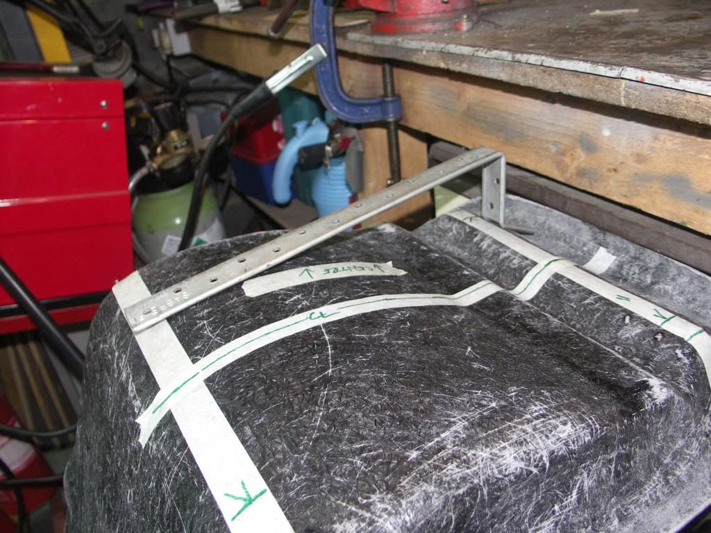 Two sides of the frame made as per the pattern. 8mm thread welded to the bottom to attach the runners. 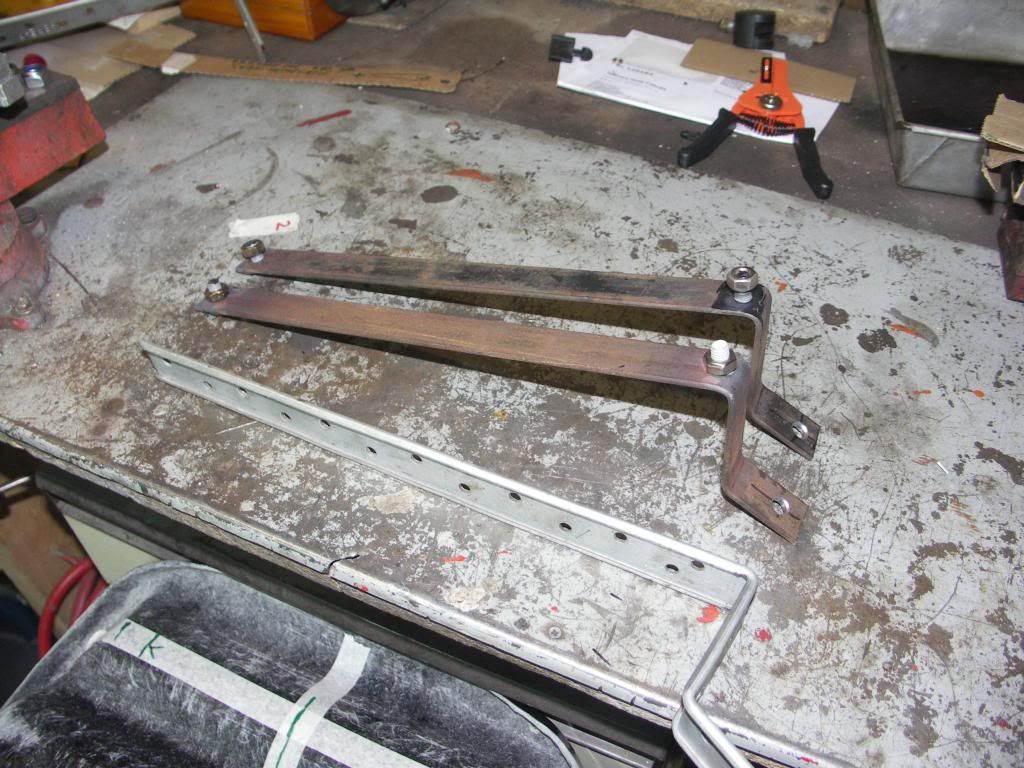 Offered up to the seat base to check the fit. 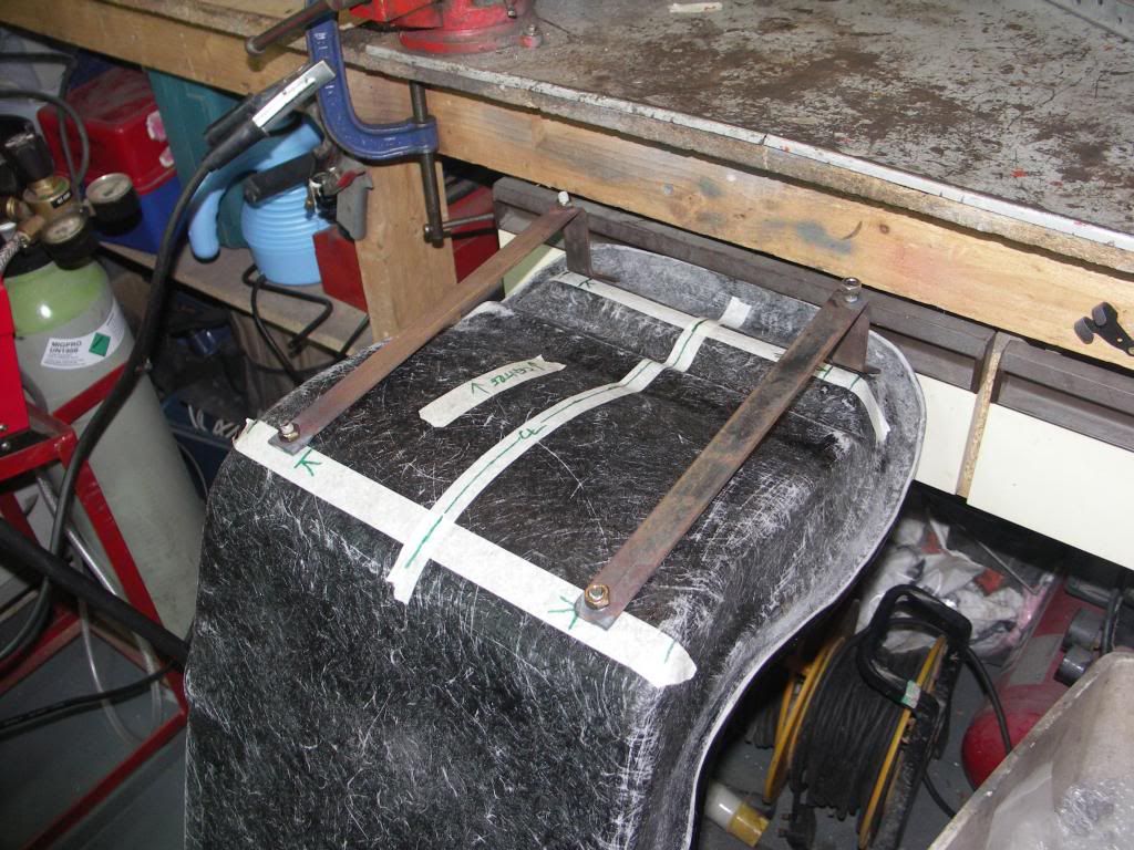 Then runners attached. All good so far. 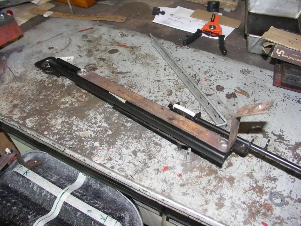 In order to bond the frames to the seat base I welded two sections of 8mm bar across the frames at the front and back. This will be fibreglassed to the seat base and it also enables me to ensure both sides of the frame are parallel ensuring the runners slide freely. 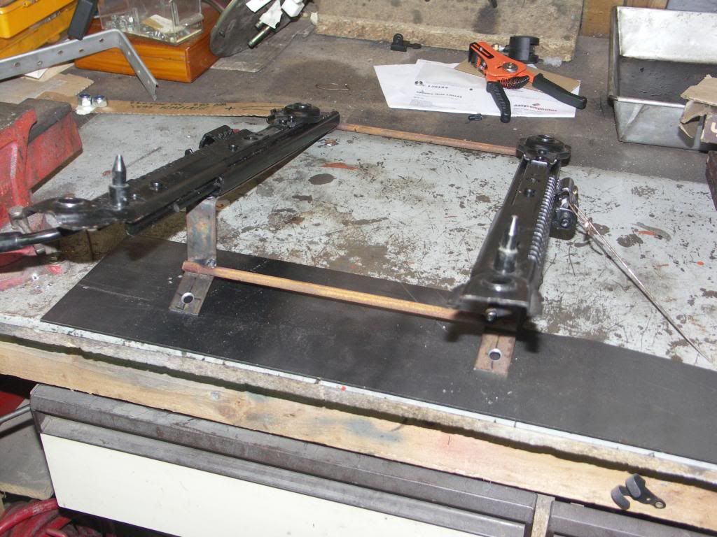 And positioned in place. 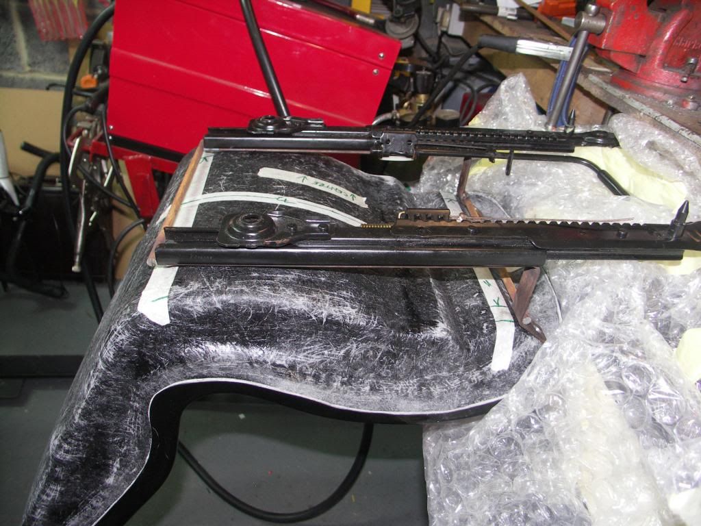 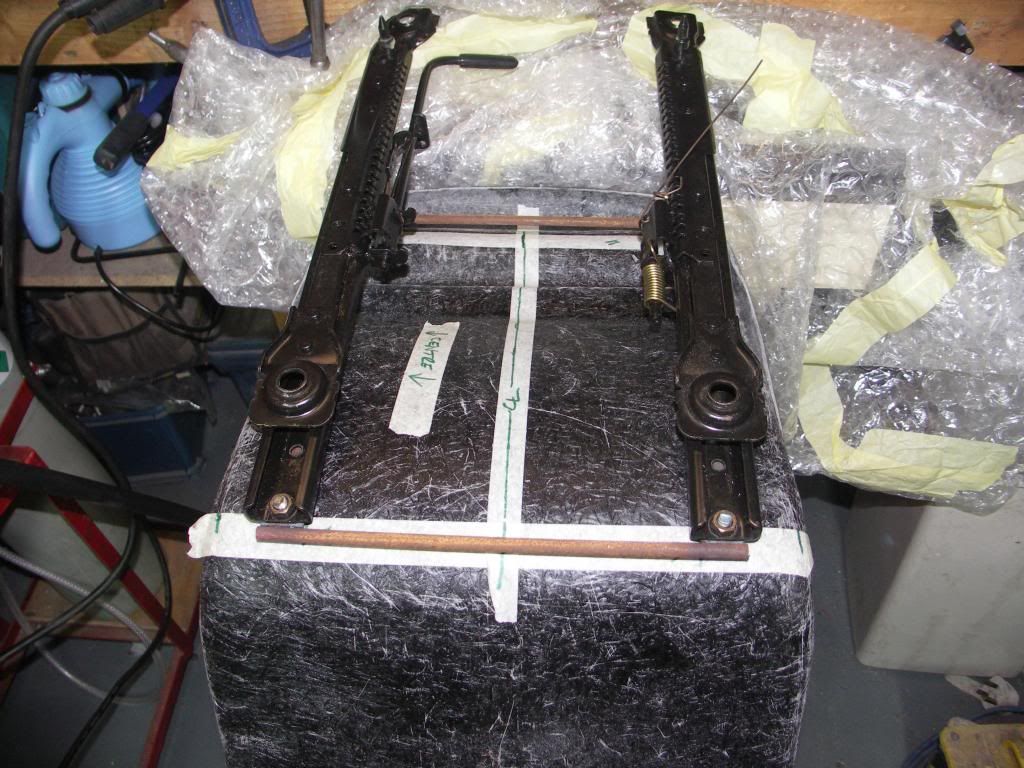 Final shot of seat frame and runner, all that's left to do tomorrow is to paint the frame and then glass the frame to the seat and repeat the process for the second seat. 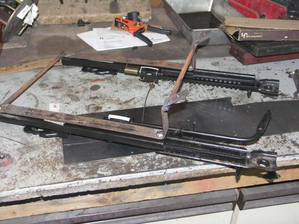 Hi mate, did you get your shocks direct from Gaz, what spring rates did they recommend, also what did they charge you? |
|
|
|
Post by jgilbert on Mar 18, 2014 21:28:02 GMT
Spring ratings are 230 and 350 as recommended by GAZ. They told me they have done a number of Exocets so where confident with there numbers. I dealt directly with GAZ. They was very help.
|
|
|
|
Post by gwnwar on Mar 19, 2014 5:26:51 GMT
I would not go any heavier then those rates.. Maybe a little lighter if only a street car as you don't have much car weight..and unpadded seats
|
|
|
|
Post by jgilbert on Apr 27, 2014 20:28:41 GMT
Relegated back to page 4, how quickly a months goes. Anyway about halfway through our build and today we was able to do a job most people start with, cutting the ali floor. The trouble with having a single garage is that space is at a premium. So the only way around this was to lift the chassis off the running gear and make some wooden supports to rest the chassis on above the running gear. The chassis and running gear split easily, one benefit of having the fuel and brake lines mounted to the PPF. Once separated the chassis was flipped over so I could work on the underside. Photo shows the 'flipped' chassis sitting on our wooden supports above the running gear. I made some tubular supports bolted to the bottom shock mounting to stop the suspension from collapsing. You can see these in the photo below. 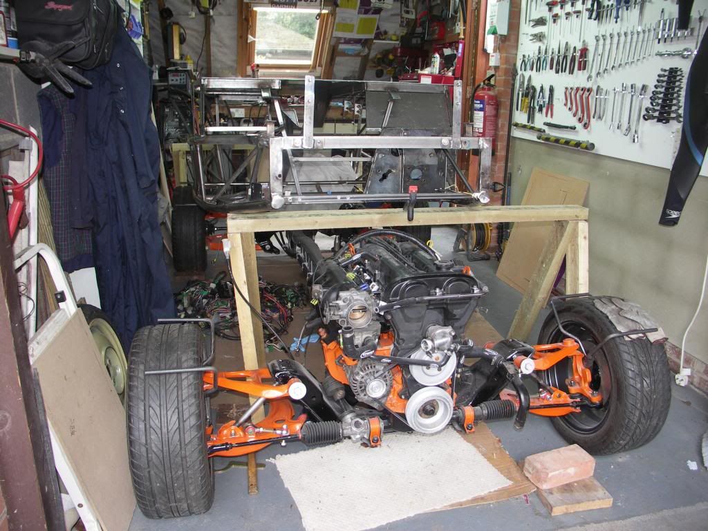 Our Ali sheet has been laying against the side of the garage ever since we got the kit so it was nice to make some progress and move it. 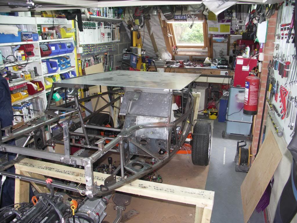 And finally, in between the rain, managed to cut both sides and start drilling for the rivets. 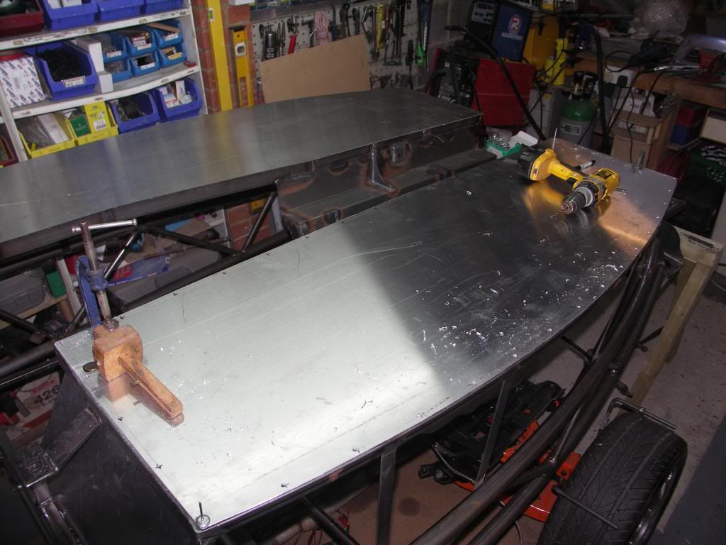 |
|