|
|
Post by scooby1929 on Jul 29, 2013 20:33:51 GMT
Or better still i could make that for you no probs out of angle i have here
|
|
|
|
Post by nitram on Jul 29, 2013 20:52:30 GMT
Thanks for the offer but I'm really going for a cheap as chips build (and re-cycling old galvanized gates in the process).
|
|
|
|
Post by scooby1929 on Jul 29, 2013 21:40:08 GMT
It was gonna be cheaper than chips as in free
|
|
|
|
Post by nitram on Aug 25, 2013 10:50:23 GMT
I have a neighbour who likes an occasional dip into the Exocet forum and chanced across the latest offer from Scoobs to send me a couple of short bits of angle iron from N Ireland. He has now bullied me into making proper angle iron brackets which work as well as my older ones. End of bracket saga... on with the build. Topics go in and out of fashion on this forum and I remember the tales of trying to get reflectors to sit near to the side of the car and still cover the exo chassis end plates. There a two simple problems. Firstly, the end plates at the end of the chassis have, in IVA terms, sharp edges. 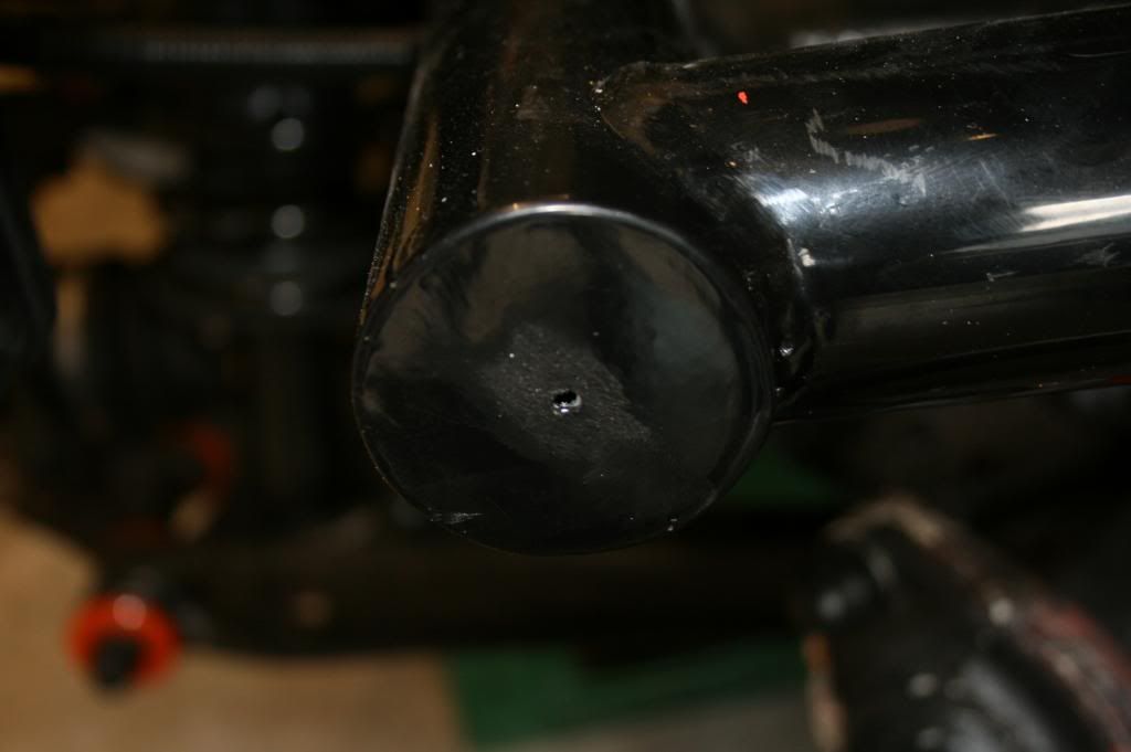 The simple solution appears to be to slap a couple of reflectors on the end plates to cover the edges up. But this leads to the second problem that the reflectors are more than 400mm from the side of the car. I know the geometry is different from build to build and that some people have no problem achieving the minimum measurement. But on mine, maybe because of the tyre profile, I've had to locate the reflectors quite a way outboard. Unfortunately I set up the rear light cluster some time ago 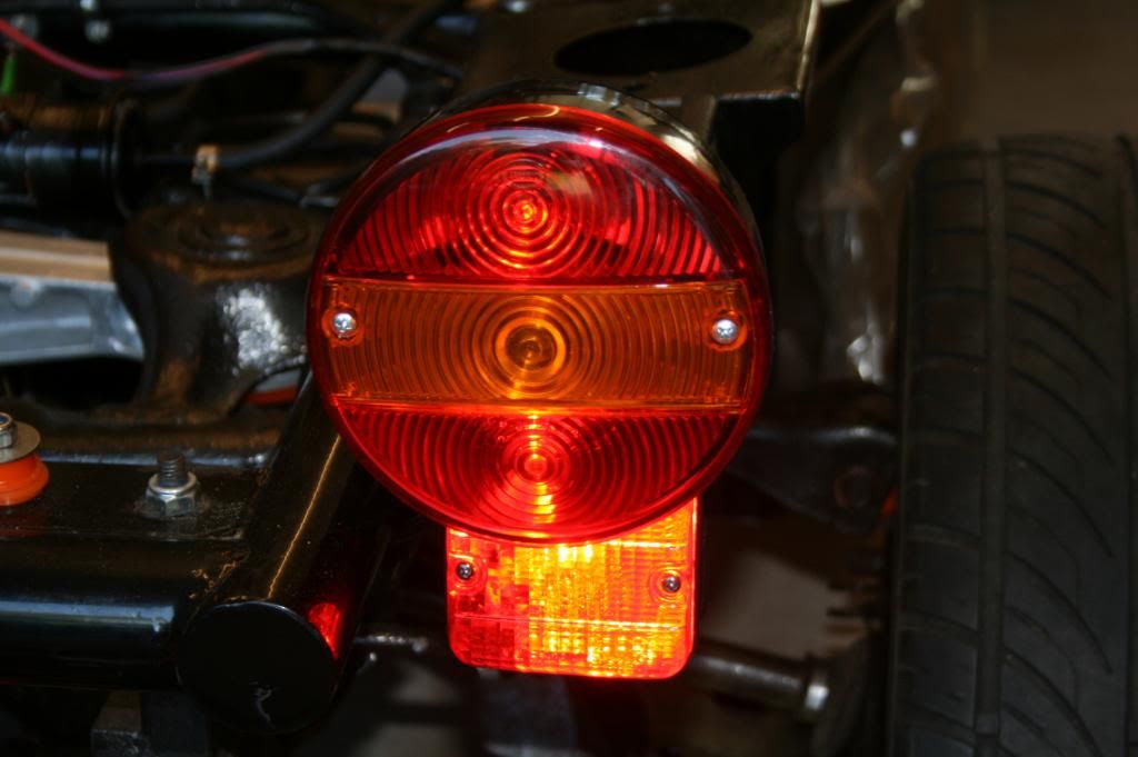 and just putting the reflector on a stalk would partially obscure the rear fog and interfere with the 25 degree angle of vision required. So the simple solution required a tear-shaped bracket, painted and trimmed to hold the reflector and a new bracket to move the rear fog a similar distance outboard. Fortunately this was achieved without having to adjust the wiring. 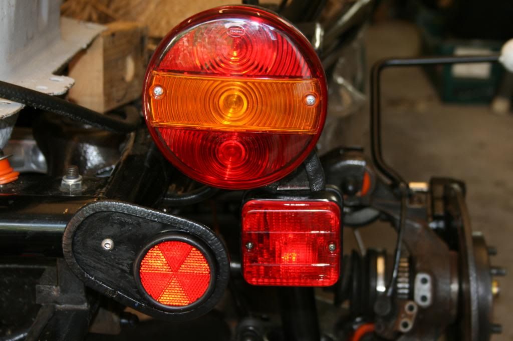 And now on to the build of the 4 corners. All springs and dampers fitted with no problems. Then realized that it would probably be easier if I started fitting the trim, nut covers , self-amalgamating tape etc etc before progressing with the build. A clumsy attempt at replicating the IVA man's balls left my wife wondering where her flower arranging Oasis had gone. 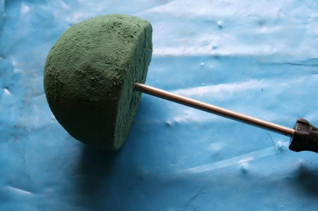 But I needn't have bothered; basically, is you can see it, The IVA man will get his balls to it 9 times out of 10. Just do the lot. Loads of PU adhesive used, very messy, sticks like a sticky thing; use gloves. 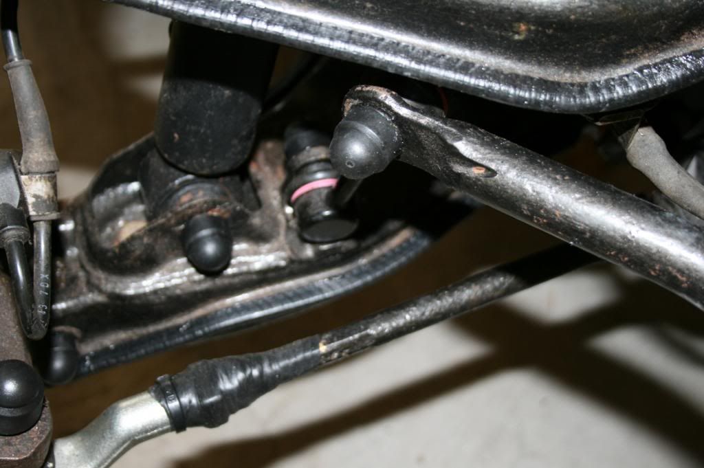 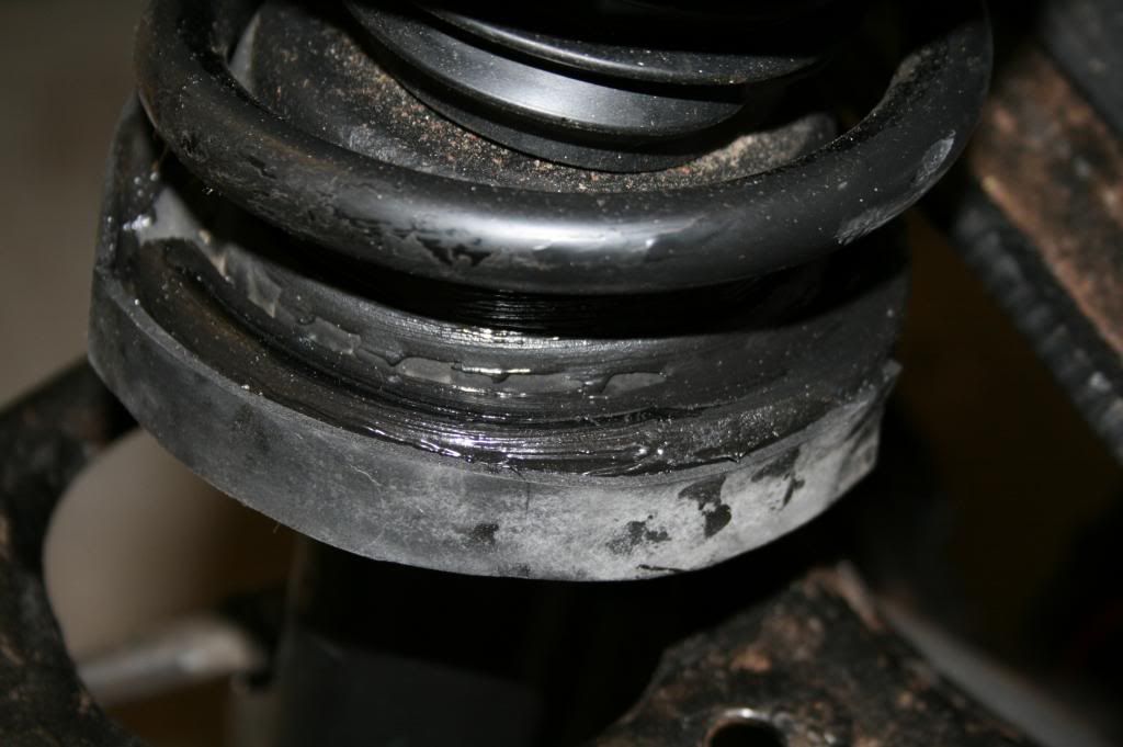 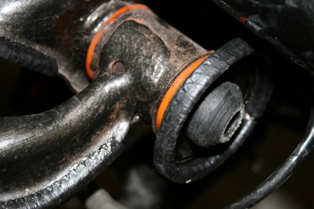 The rebuiding of the corners could then proceed reasonably smoothly. With the front wing stays in place, the hubs can go back on, torqued and staked. Brake discs, pads and calipers went on a treat, together with the wheel spacers. 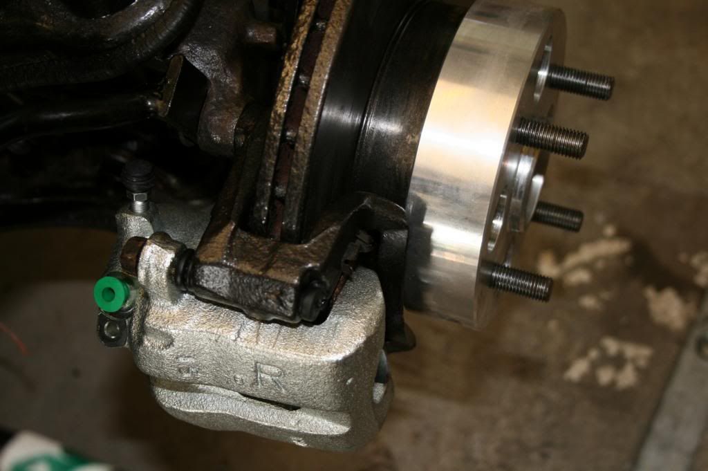 On to the manufacture and fitting of the brake pipes. The front to rear and rear transverse pipes were installed eons ago. So just the front ones remaining. I had not been looking forward to this but it turned out to be quite interesting and rewarding. The front brakes' flexible pipes require brackets to hold them to the frame. the build guide suggests bolting them to the sub-frame but there did not seem to be on obvious place on mine (Mk2 ?). I finished up bolting to the exo chassis having experimented with brackets clamped on at various angle first. The aim is to avoid tension on the flexible pipe on one lock and to avoid a foul on the chassis or tyre when on the opposite lock. I finished up with this geometry with the bracket angled inwards about 45 degrees. 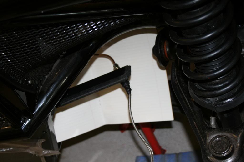 The pipework went bent, flared and fitted really well - better than I expected and I am pleased with the end result. 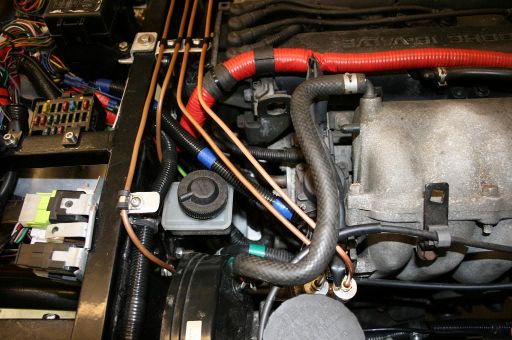 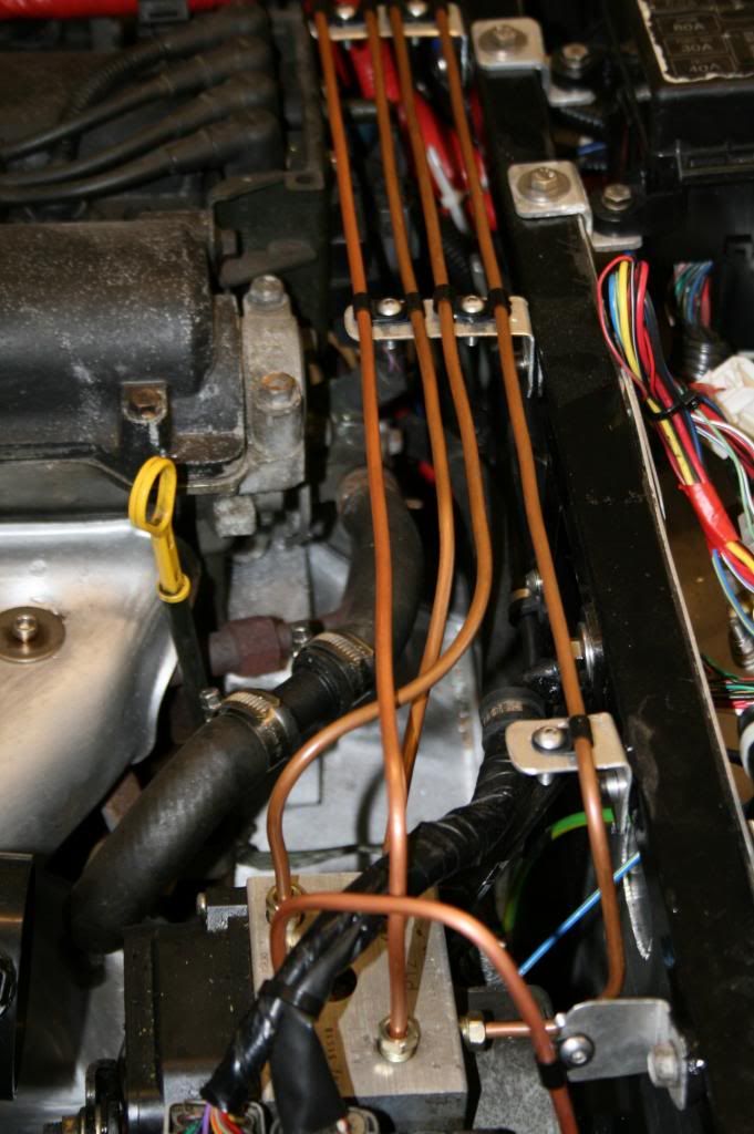 Of course, the proof of my work will come when brake fluid is put in and the system is pressurised. All in all, quite pleased with progress.  |
|
|
|
Post by gwnwar on Aug 25, 2013 18:33:25 GMT
Nice neat tube work.. Are all tube ends double flared.. See you turned around your fuel tank also..
|
|
|
|
Post by nitram on Aug 25, 2013 20:35:28 GMT
The five male connections than fit to the ABS module and the two that fit to the master cylinder are doubled flared. The two female connections that fit to the unions for the left and right flexible pipes are single flared. Yes, I turned the tank through 180. See my previous post: "Presumably this is another of the idiosyncrasies of trying to get an Mk2 donor mated to an Mk1 designed kit. However, turning the tank through 180° reduced the foul considerably and allowed the mounting brackets to be used. Read more: www.mevowners.proboards.com/thread/3069/nitrams-build?page=4#page=1#ixzz2d0yd |
|
|
|
Post by nitram on Sept 23, 2013 15:52:56 GMT
Next job was the handbrake. The transmission tunnel needs to have a bit removed to allow the driver's side handbrake cable to reach. I decided to cut a slot - a bit fiddly but, I thought, easier than trying to drill a large-ish hole, like others have done. But the main problem was trying to thread the cable from the back of the transmission tunnel to the brake unit. Over a period of time, this cramped little area at the back of the tunnel gets filled with two longitudinal and one transverse brake pipes, two fuel pipes, two looms that split eight ways and three earth points. All of these bits were fitted on a first come basis and the area was an uber rats nest. So, spent a couple of hours repositioning things and fortunately didn't have to connect and reconnect too often. The end result was a lot neater and allowed the handbrake cable to be weaved through. 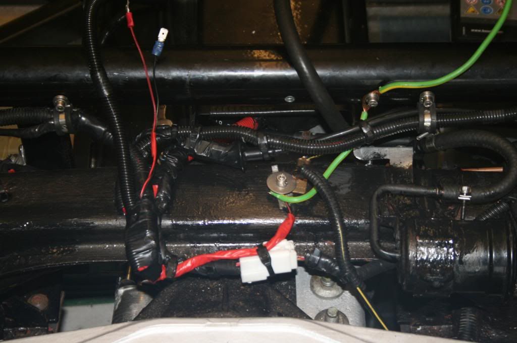 I also took the opportunity to remove a "floating" joint where the copper fuel line joins the rubber and which, apparently, is not liked in the IVA test. I remembered to adjusted the adjuster on the two rear calipers using an allen key to wind-in the pistons until touching and then backing off a third of a turn. The handbrake goes on reasonably easily remembering to leave the adjusting nut in a slack position when fitting and only tensioning when the handbrake is firmly bolted to the tunnel. I used 8mm rivnuts. 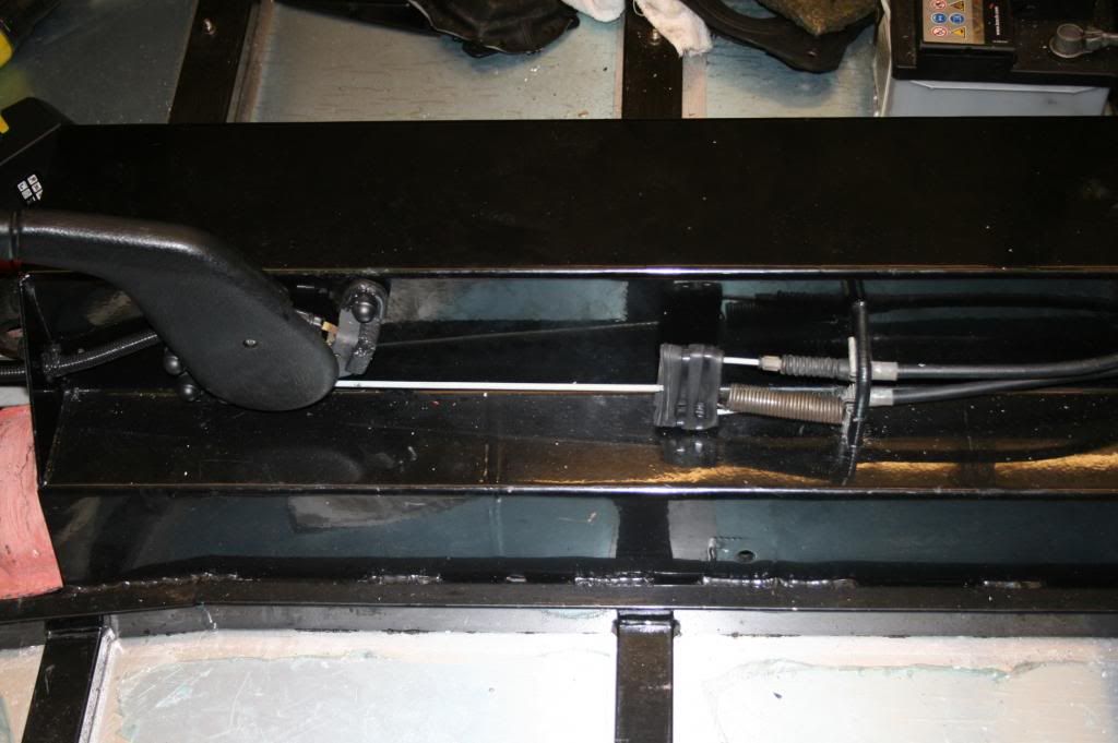 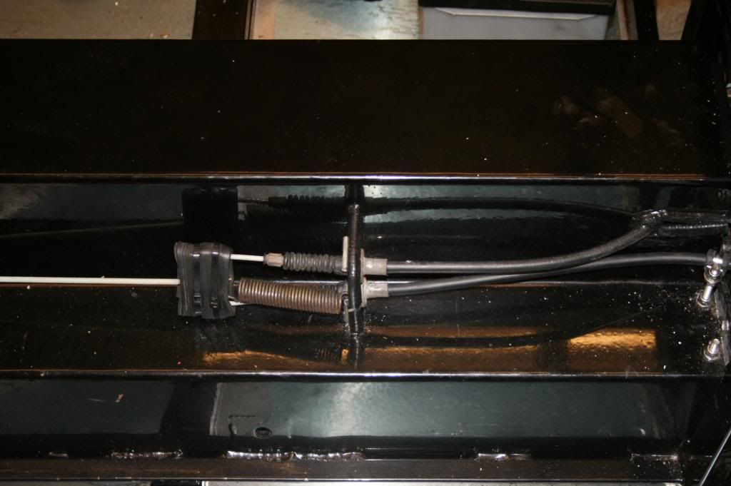 Borrowed my neighbour and bled the brakes. Conventional method: pump brake pedal; hold down, undo nipple and allow fluid to flow through tube to container; tighten nipple; release brake pedal; repeat until clear fluid bleeds off. Went surprisingly well; I thought I would have extra problems because of the ABS module in-circuit. No problems. Buoyed with success, decide to bleed the clutch. Similar method. Nothing. Convinced myself that the operating rod required adjustment. The exo bulkhead is different from the MX5 bulkhead so the distances may be different, or not. Nothing. After a frustrating session of winding in and out, decide to slacken off the pipe at the master cylinder. No fluid coming out when the pedal pressed. Nothing. The master cylinder must be faulty even though it was working when it came off the MX5. Removed the master cylinder - easier said than done as everything had been built around it. Dismantled - only required the removal of one circlip - and cleaned. Got a few mls of disgusting gunge out of it (spiders dissolved in hydraulic fluid?); washed out with clean brake fluid. Reassembled and worked a treat, once I had adjusted the piston roughly back to where it started! Fitted the handbrake electrical switch. This switch shares the same circuit as the brake fluid contents low indicator so with the brake master cylinder now filled, everthing works as advertised. I think this now means that the only circuits that I have not proven is fuel tank contents but this will have to wait until I have more than one litre of fuel in the tank. Talking of fuel tanks..... I have seen mention of a recent IVA failure because there was no heatshield fitted between exhaust and tank. I don't have one. Looking in the workshop manual for the Mk2 there is an item which resembles a kitchen sink and drainer combo and labled heatshield. I don't have one. Didn't come with the car. The IVA manual doesn't actually refer to a heatshield in as many words but wants something to prevent any leaks from the tank going into the passenger compartment or dripping on to the exhaust. The chances of a tank leaking without being in a major shunt must be pretty slim. On balance between a "heatshield" and an air bag I'd rather have the air bag which is expressly forbidden. I digress. Made up a "heatshield"/drip diverter out of thin bent sheet and bolted in place. 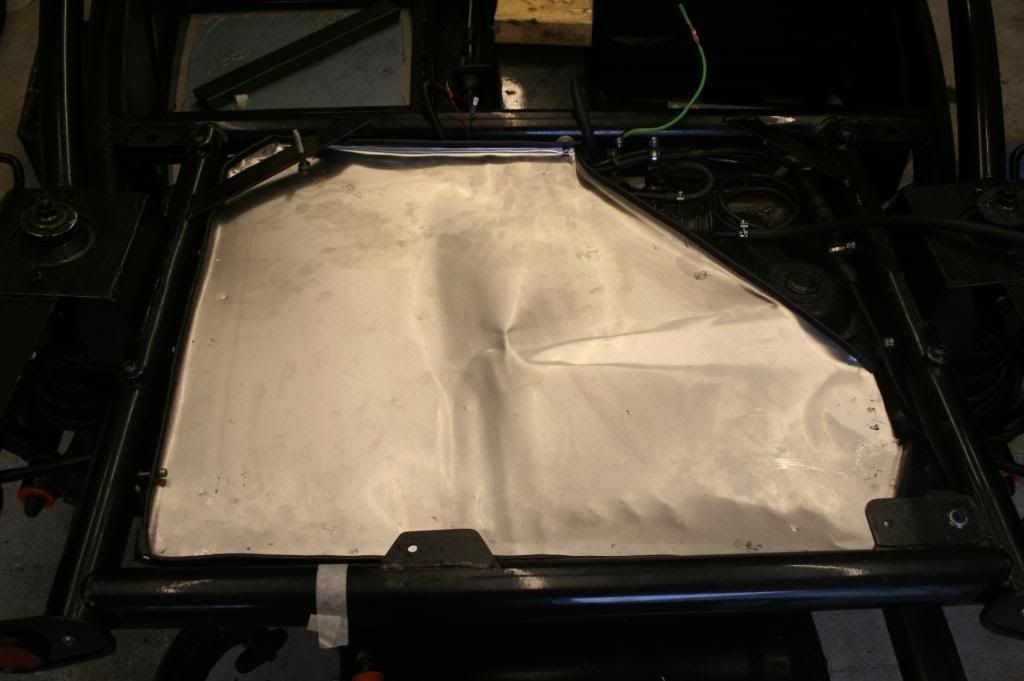 Fitted the fuel tank, hopefully for the last time, using some foam rubber to prevent chafing of the rubber pipes. 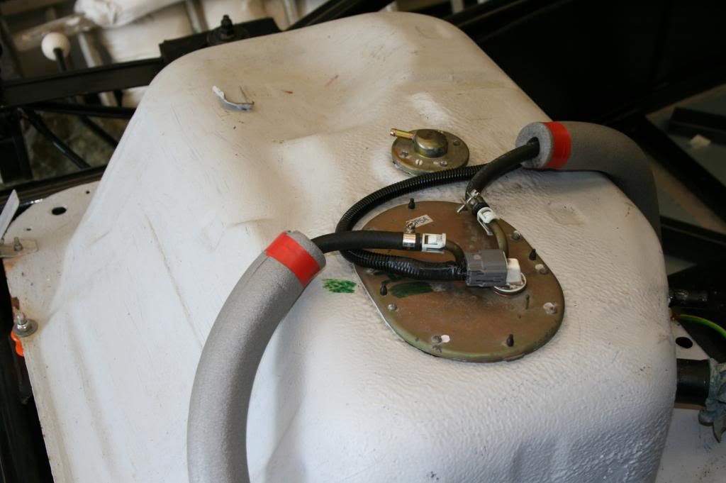 Next, I thought I would have a look at shaping and fitting the aluminium bit of the tramsmission tunnel. The rear end of the aluminium bit has roughly the same profile as the steel tunnel so I would have expected the gear lever to sit roughly in the middle of the top of the tunnel. Now, for the first time, I have realised that the gear lever (and hence the gearbox, and transmission shaft) are off-set to the left by about 60mm. 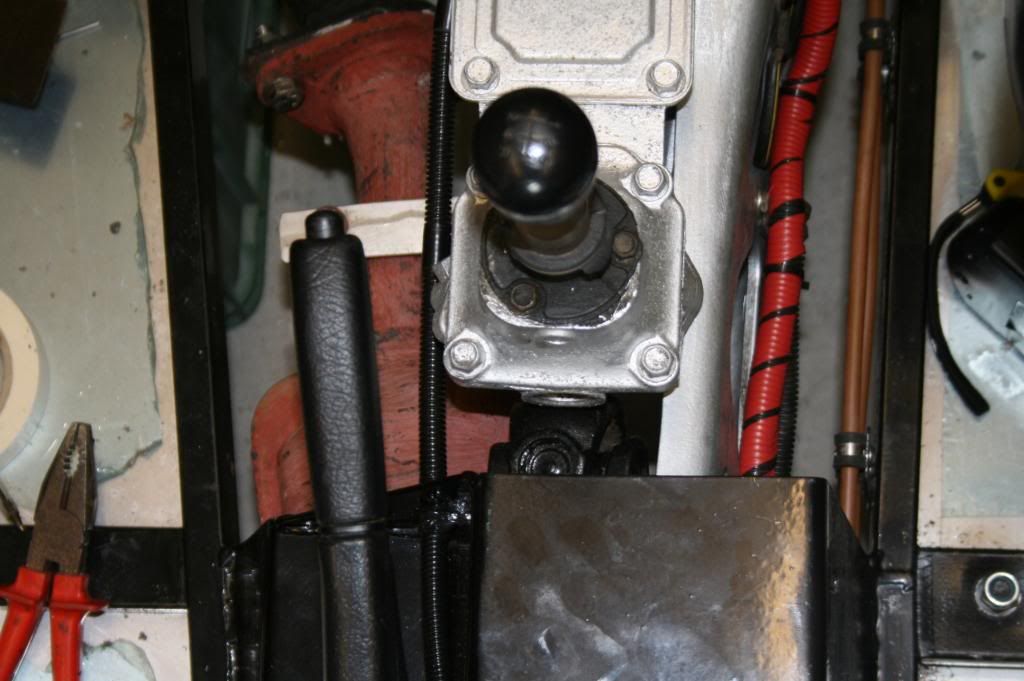 In addition. the housing (the bit with the four hexagonal bolts) sticks up about 15mm above the tunnel surface. Whats going on? What do I do? Help! |
|
|
|
Post by red5 on Sept 23, 2013 20:03:55 GMT
Hey buddy nice work so far v tidy.
Re centre consul - its a mare , helps if you put a cut in the pax side on the bottom flange where the chassis turns in a bit - for what its worth I had to build one side up by about 25mm ( pax) so that the other sat flush , and carpet the gaps!
also check the distance from your fog to your stops - needs to be 100mms
|
|
|
|
Post by nitram on Sept 23, 2013 20:29:35 GMT
Thanks Red5.
I've got 109mm between fog and stop - my page 2, 28 May.
What I really need to know is: should the gear level be in the centre of the flat top of the tunnel? In other words, do I have a significant for and aft alignment problem? Anyone got photos to show where the gear lever should sit?
Thanks
|
|
|
|
Post by red5 on Sept 23, 2013 20:47:56 GMT
Slightly offset mate - not massively , the hole you need to make is surprisingly big ( as a guide think about the size of the gator surround off the donor), so alignment isn't too much of a snag.
again good luck
|
|
|
|
Post by gwnwar on Sept 24, 2013 2:17:47 GMT
To drop the rear of the gear box loosen the 2 bolts holding the PPF to the box.. move the box down some.. There are slots in the bracket.. Not to much you need to keep box and diff mostly in line.. don't want to over work the J joints..
|
|
|
|
Post by nitram on Sept 24, 2013 14:46:47 GMT
Thanks gwnwar. I didn't find it as easy as it reads. Loosened off the two long bolts holding PPF to gearbox. No movement. Then remembered that there is a third bolt. Loosened that (and the two that hold the bracket to the gearbox). A little movement but when released, everything wants to spring back to the "bent" position. Loosened off the two long bolts holding PPF to diff. No additional movement. I'm beginning to think that I may have put in the misalignment when I bolted the engine to the front sub-chassis or the diff to the rear sub-chassis. Loosened off these two pairs of bolts. No additional movement. I can roughly align the components but only if they are held in place. So, using a G clamp lined the gear lever up with the centre of the tunnel... 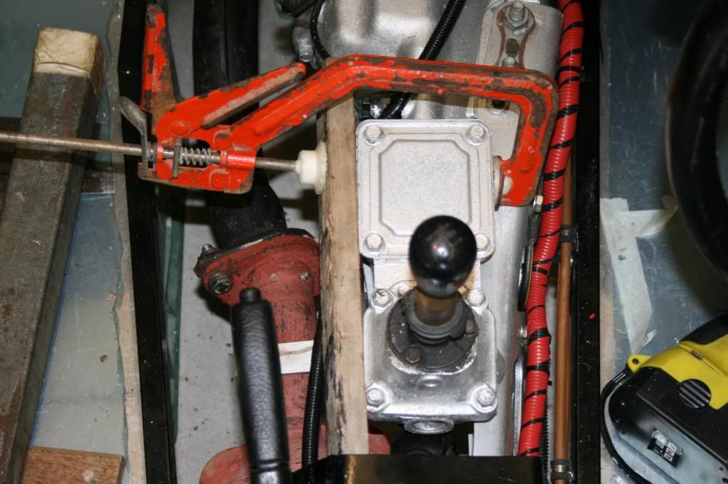 and then quickly torqued up all the bolts before they could change their minds. Releasing the G clamp allows the transmission to spring back a little but not nearly as offset as before. 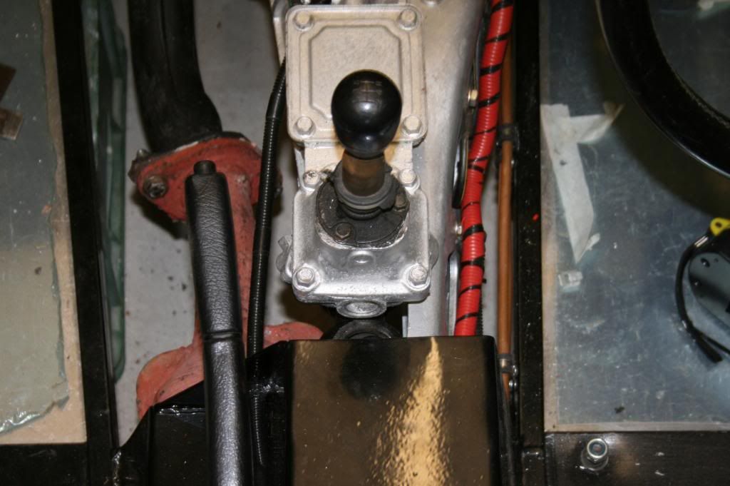 I'm now reasonably confident I have enough wriggle-space to have a go at fitting the aluminium bit of the tramsmission tunnel. Wish me luck - all the threads say this is a pig of a job. |
|
|
|
Post by gwnwar on Sept 24, 2013 23:19:59 GMT
The 2 long bolt at the trans are more for up/down of the tail shaft.. I would not bind up the left right moment
of the tail shaft.. Try running a spring from end of the trans tail shaft center bottom to the center of the rear/diff flange see if you have a straight line with the drive shaft.. You might end up loosing the engine mounts at sub and mount lower bolt and pushing the engine/trans tail shaft over some. retighten and check make the line straight.. Put string line from trans tail shaft to read up/down of the J joints can be a few deg off up/down.. Don't need to be dropping a shaft on the motorway..
|
|
|
|
Post by nitram on Sept 25, 2013 12:18:54 GMT
Everything is reasonably straight-ish. I had the bolts holding the engine to sub-frame loosened off while I was doing the grunting. I'm happy with what I have at the moment but the car is still on axle stands; I will re-visit the issue when it has been bouncing around on its wheels for a while.
|
|
|
|
Post by nitram on Oct 23, 2013 19:58:11 GMT
The last post saw me attempting to align the gearbox and prop shaft to the centre of the chassis. After expending a few thousand calories, I was quite pleased with the result. A couple of days, later, however, I found a little pile of shredded rubber under the car. Rotating the engine by a degree or two had moved the PAS pump drive belt a few mms against the PAS pipework and the bracket on the end of the pipe was slowly chewing through the belt. 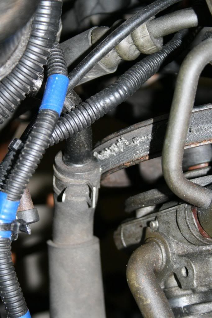 Fortunately there was enough space to get a 2 pound lump hammer in to redesign the bracket and apart from the cost of a new belt and the loss of a few hours, no harm done. I could now get back to the job I had started, the cutting, painting and fitting of the of the aluminium gearbox cover. This is a tedious, iterative process but with the use of a few hundred cardboard templates the end result is quite pleasing. 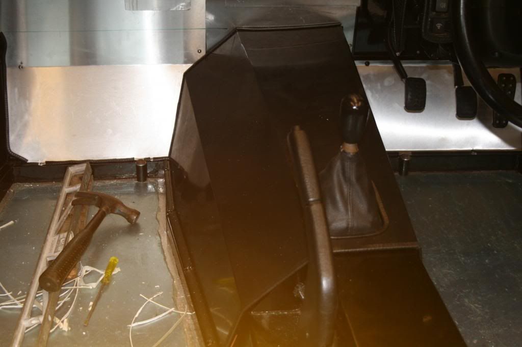 The nose cone had previously been shaped but it was now time to bond on the grill. The grey stripe is my only concession to bling. I was going to go for a black kit until I saw, a few days before I put my order in, a Lotus Elise in the yellow and grey livery and changed my mind on the spot I wasn't going to bother with the strips until after IVA. I became obvious, however, that the nose cone would be better striped before the fitting of the grill. Which is what I did. 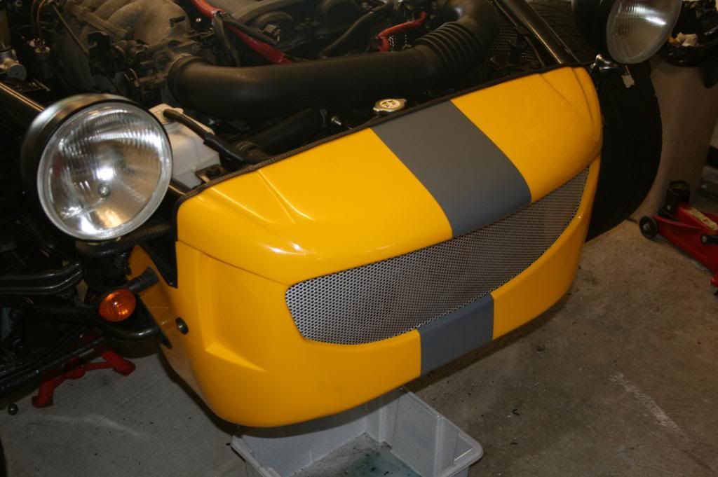 Wlile I had the wet sponge in my hand (make up your own joke), I striped the rear end 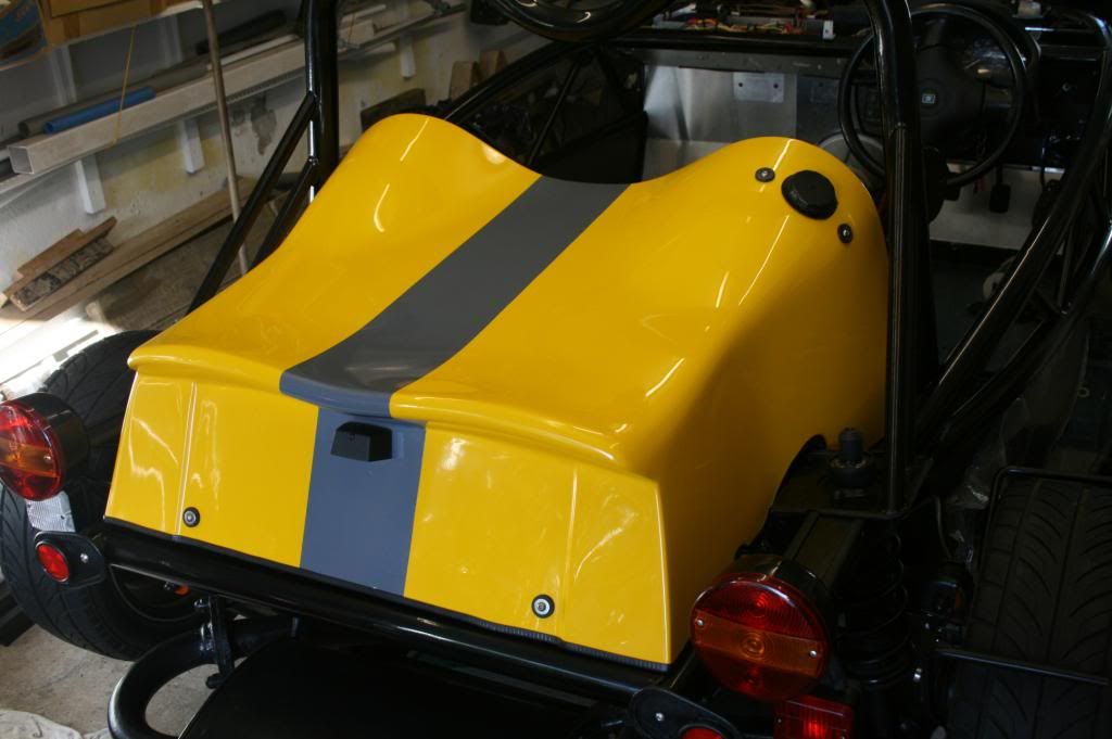 On to the bonnet. I bonded on a few aluminium stiffeners where the bonnet catches and wing mirrors will sit. 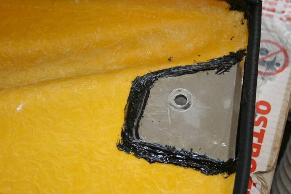 and the little bonnet grill 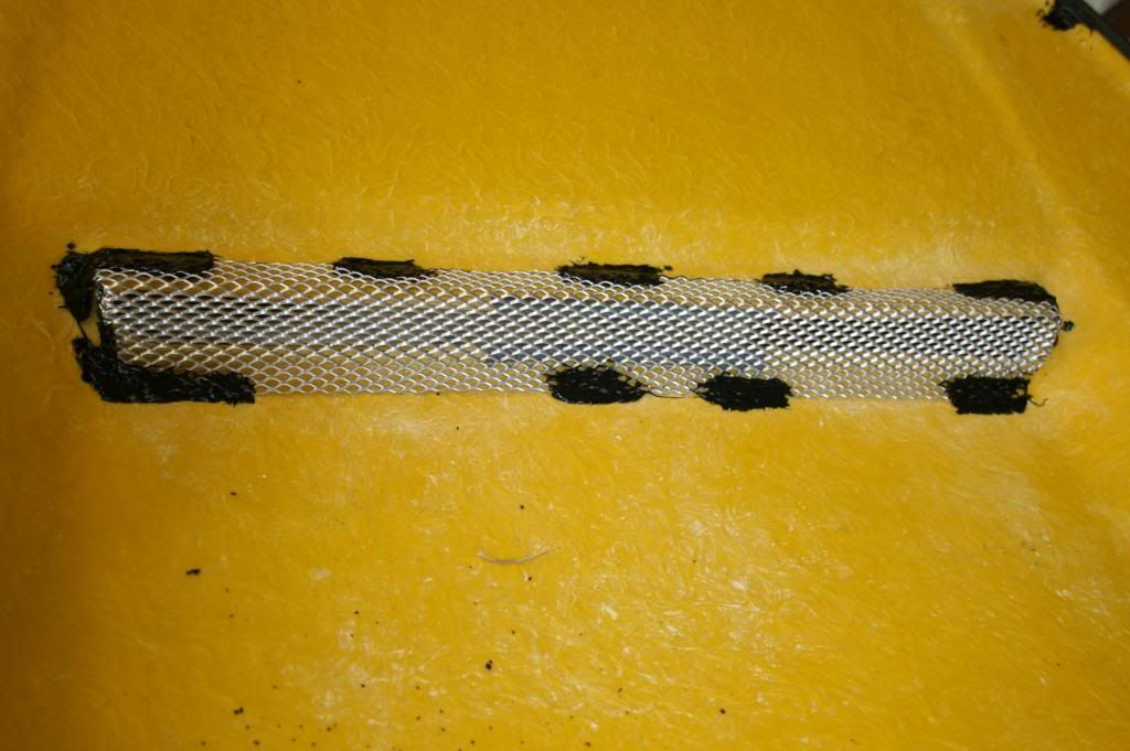 and a heat mat 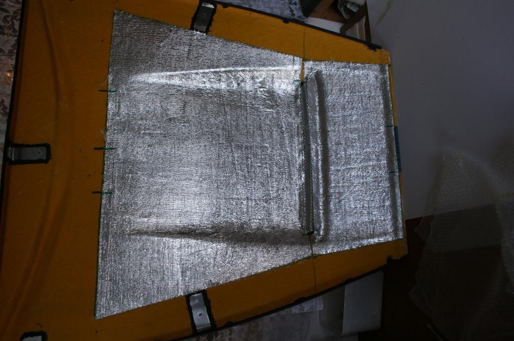 The bonnet in place 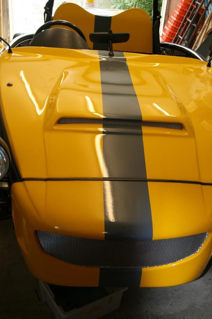 The "interior" mirror is from the MX5. And the driver's mirror (not the best of photos; the camera wanted to focus on the reflection). 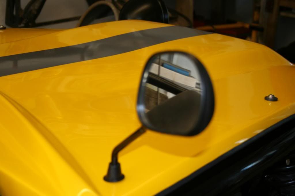 The rear panel was fitted with the aid a few more templates 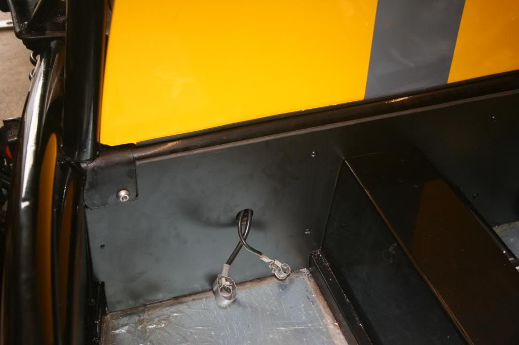 and then the mats, seat belts and battery box followed in quick succession 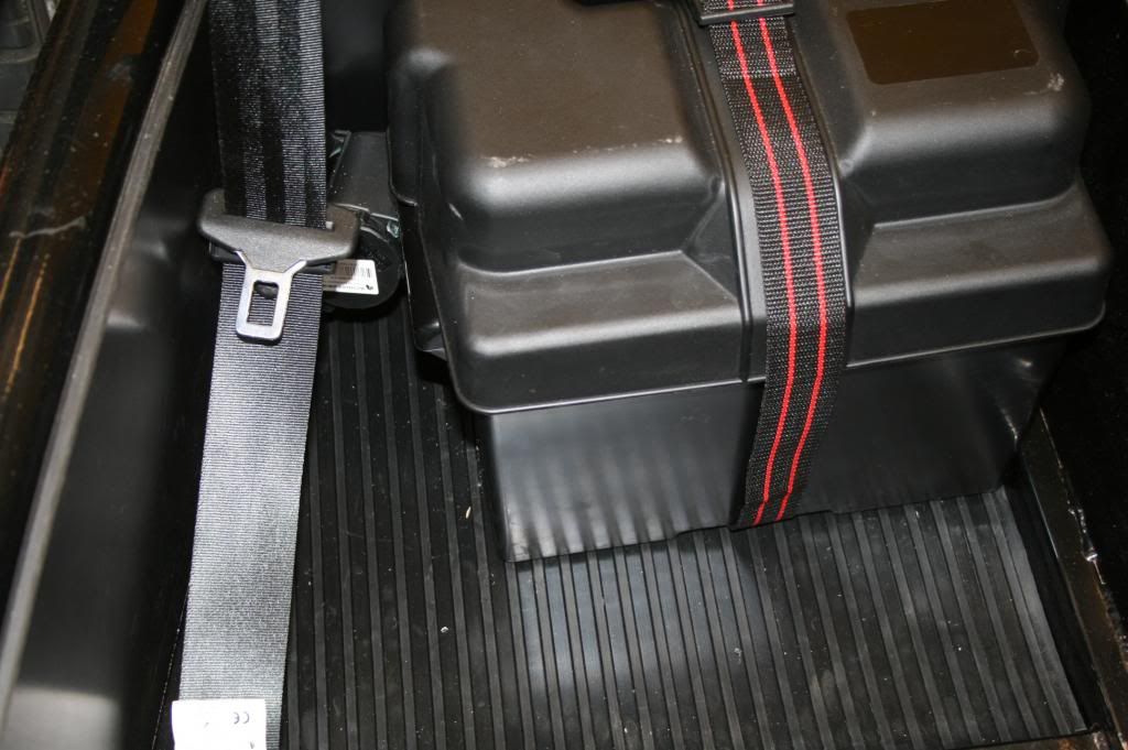 I'm quite pleased with progress 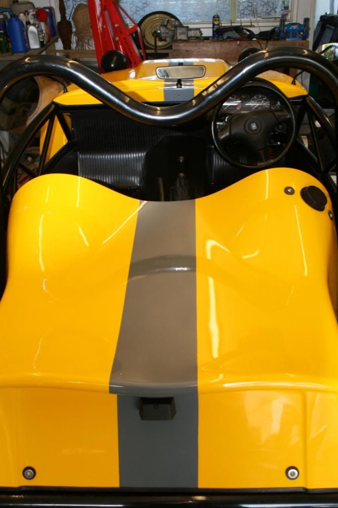 but there are still a hundred little bits and bobs to sort out. My clutch only seems to be travelling about half way in spite of a lot of bleeding and I'm not particularly happy with the rear end with the MX5 silencer dominating like a dominating thing. 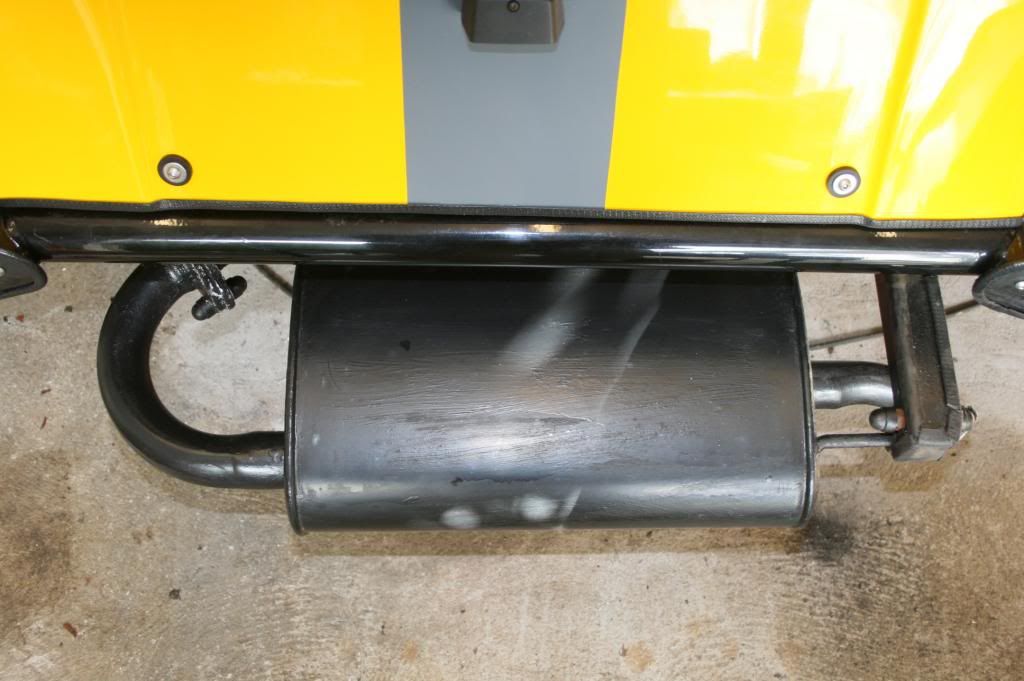 It does the job, its quiet for IVA and I don't want to spend more money than I need to; perhaps I will try and design a discrete cover. The next major task has to be the fitting of the wings and I'm already getting those GRP cutting jitters. |
|