|
|
Post by jgilbert on Jun 22, 2013 20:12:20 GMT
Agree with Scooby's comment. Good work. Have been looking at my dash and am following a similar approach re mounting and cutting the dash pod where it meets the bonnet.
Liking the bracketry for the switches beneath the dash.
|
|
|
|
Post by scooby1929 on Jun 22, 2013 20:16:11 GMT
I cant quite follow how you can trim the pod back as mine needs lengthened?
|
|
|
|
Post by nitram on Jun 22, 2013 20:26:42 GMT
Remember that I had a Mk2 mx5 and I think you had a Mk1. On mine, the instrument cluster only comes just over half way along the pod. The pod then has an empty curved bit where it used to fair into the dash and a 50mm pointy plastic thing on the end. To use the technical expression: a waste of space.
|
|
trident
Senior
   Improvise, Adapt and Overcome
Posts: 629
|
Post by trident on Jun 23, 2013 18:21:16 GMT
I cant quite follow how you can trim the pod back as mine needs lengthened? Mine was cut back too in order to make my dash and I've got a MK1.. |
|
|
|
Post by nitram on Jun 23, 2013 19:03:10 GMT
Scooby might have to produce a photo.
|
|
|
|
Post by nitram on Jun 26, 2013 15:28:38 GMT
I’m beginning to think that, as I had picked a Mk2 donor, I had done something very bad in a previous life. Little idiosyncrasies creep into the build that don’t seem to have caused so many problems with the Mk1 donor. Chassis fit, fuel tank, exhaust, electrical loom…. but I like a challenge and would not change my little Mk2 donor for the world, he sighed. On to the exhaust that I have been putting off for some months. The bendy shape of the Mk2 exhaust means it will not fit down the straight transmission tunnel. 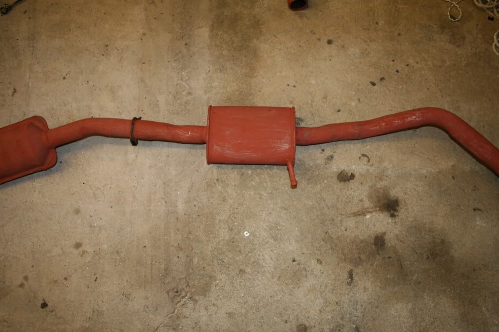 The mid-box is also too wide to fit in the tunnel even if the pipes could be straightened. The problem appears to require a solution along the lines of: 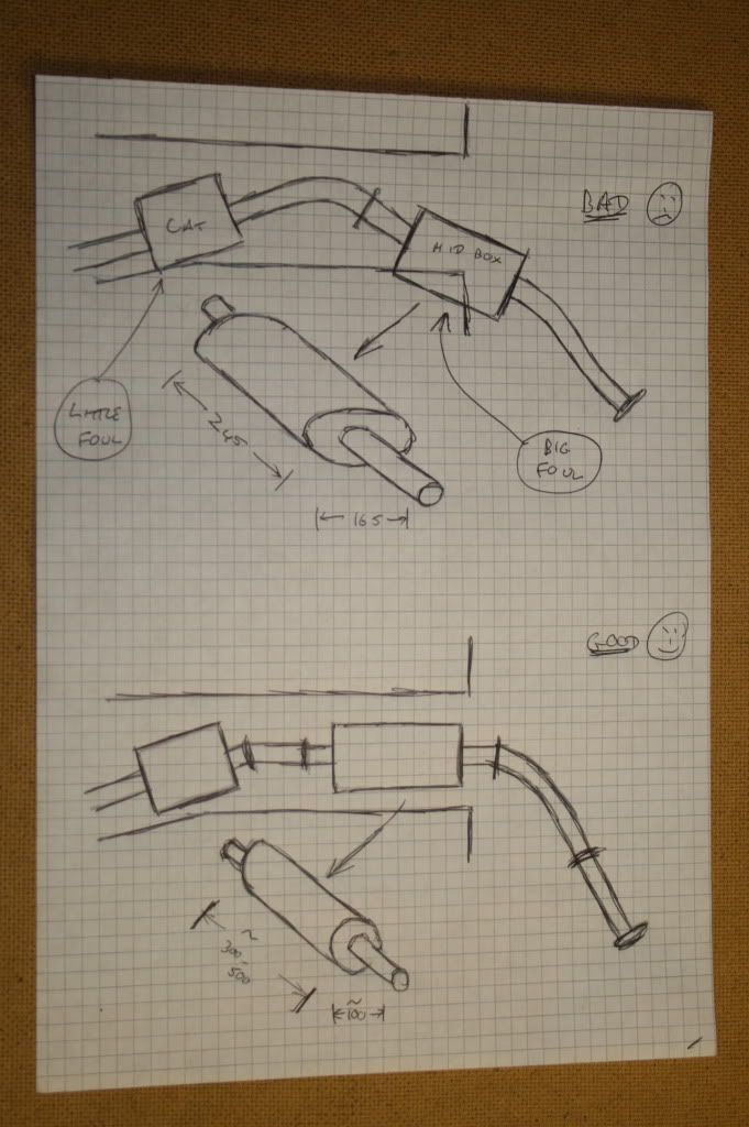 Off to the local Kwit-fit. “I’d like a circular-section intermediate box about 100m wide, 300-500mm long and with 50mm pipes on either end” “What’s it for?” “MEV Exocet” “Never heard of it” “It’s a kit car based on a Mazda Mx5 donor” “Ah, so you want a Mazda box” “No” “Would you like to look in my stock room?” By now the major alarms are going off in my finely-tuned B**ls**t detector. The stock consists of two complete exhausts, one for a Mondeo and the other for a Polo. “We don’t keep any stock; we get an hourly delivery from the warehouse in Redruth. I’ll give you their phone number” “Thank you” The warehouse is an Aladdin’s cave of exhaust art work. Thousands of different types, hanging vertically from racks. Dispensing with any health and safety formalities, I’m allowed to roam to my heart’s content. After measuring, measuring, measuring, I finish up with the intermediate section for a VW Caddy II 95-04. £28. Grinding it to size, a couple of short lengths of flexi-hose, 4 clamps, lashings of exhaust paste and Bob’s your uncle. 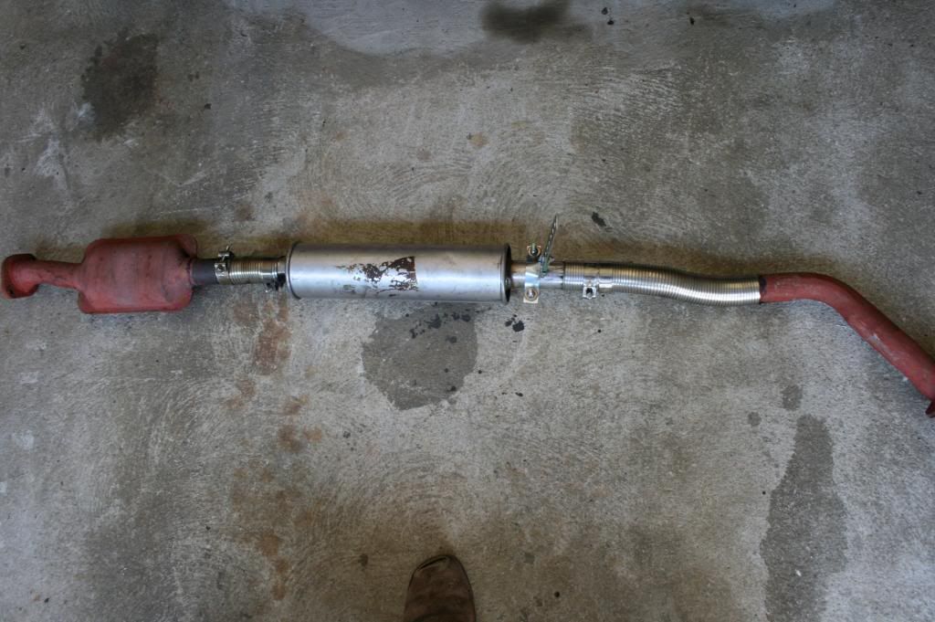 Works a treat with no leaks and quiet as a mouse. I’m still using the Mx5 back box (does my b*m look big with this?) at least until after IVA. Next nightmare challenge will be the fitting of the seats. |
|
|
|
Post by nitram on Jul 5, 2013 13:42:57 GMT
The fitting of the mx5 seats…. There have been upwards of a dozen contributors on the somewhat vexed subject of re-cycling the Mx5 seats into the Exocet, in recent weeks. It’s quite obvious, though, that Mx5 seats come in all shapes and sizes and good advice for one builder may not work for another. So, from the outset, I declare that I am talking about the seats from my Mk2 ’99 donor. The seats don’t fit. The problem comes from the tilt mechanism and its plastic cover. The bit shown here: 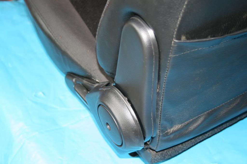 When fully forward, the plastic cover jams against the vertical bar on the exo chassis and the seat cannot be slid back more than a few mm before it jams on the side panel as the chassis tapers towards the rear. Removing the plastic cover provides about 10mm of extra clearance. This is still not enough for the seat to slide back for a comfortable driving position for me. In any case, with the cover off, several jagged edges are exposed. These have the potential to chaff the seat belt and hence lead to an IVA failure: 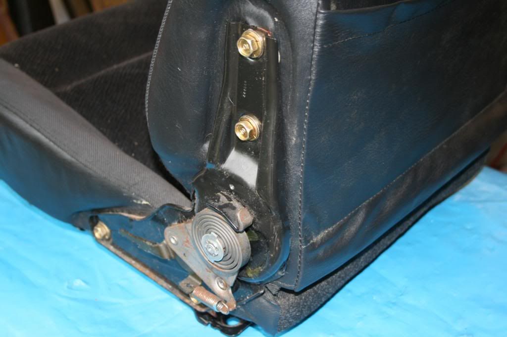 Also, please note from that image the potentially finger-removing spring; take care. Here are a couple of photos showing the mechanism removed from the seat (it stands 40mm high) 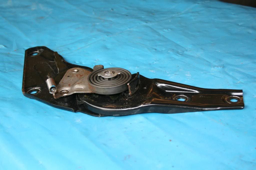 and with the plastic cover fitted (now standing 50mm high). 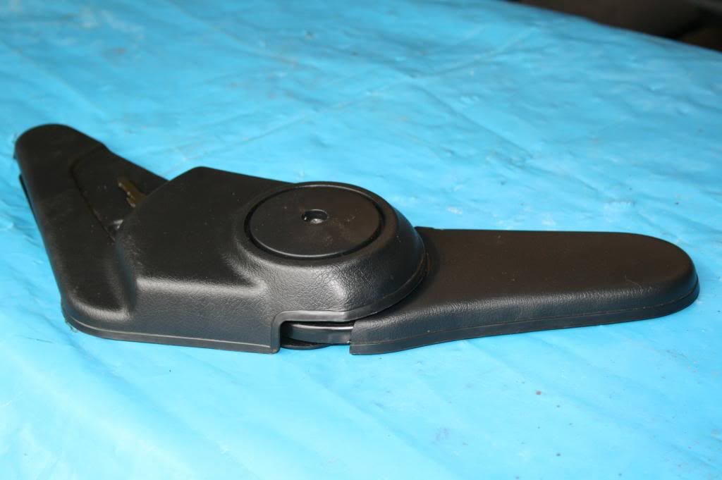 My solution, like smithers, was to discard the tilt mechanism completely after deciding on a “neutral” comfortable driving position (and the passenger gets what I like!). I manufactured a couple of mild steel plates, to the same shape as the tilt mechanism brackets, shown here painted and with knock-on trim fitted. 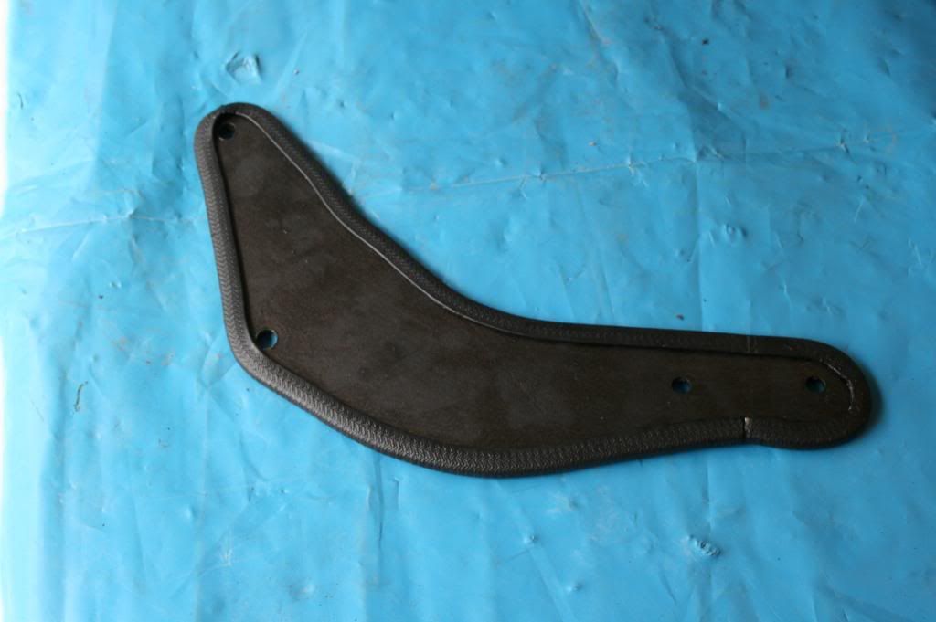 and fitted to the seat 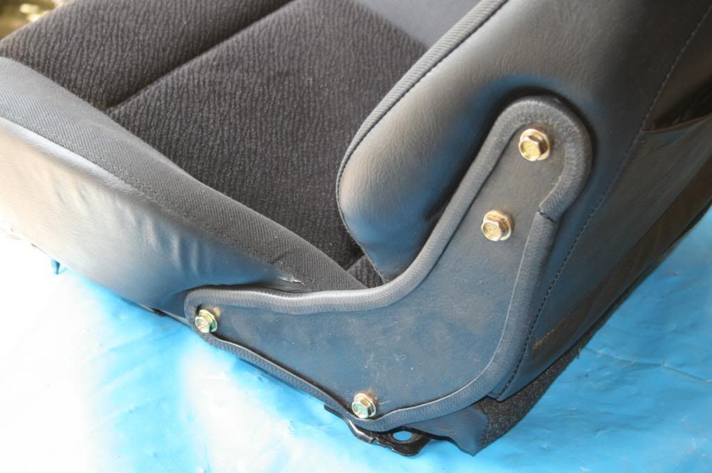 This allows full backwards and forwards adjustment. I’ve used the original 10mm bolts and these will be capped to protect the seat belt. I used 5mm steel plate and am prepared to argue that this is substantially more robust than the original plate which held the tilt mechanism and which is less than 2mm thick. Cutting this amount of 5mm plate with a jigsaw is tedious but with the right blades and loads of lubrication, both plates took about 2 hours to manufacture. I think I have seen somewhere on the forum a report of an IVA failure because load spreaders for the seat bolts were not fitted under the floor. Although I have only found reference to non-metal floors in the Manual, I’ve taken no chances and used some 5mm steel spreaders. A mention about procuring metal. Early on in the build, I visited my local metal fabricator and persuaded him to let me have a rummage in his scrap bins. I filled 3 carrier bags with off-cuts, some quite large, both steel and aluminium, both sheet and angle. £10 well spent. The sun has come out. S*d the built, let’s get the BBQ fired up. |
|
|
|
Post by gwnwar on Jul 5, 2013 15:20:02 GMT
Nice job on the seat bracket. Only change I would make is move the ends of the trim to the bottom edge
for a more OEM look..
|
|
|
|
Post by nitram on Jul 5, 2013 17:03:00 GMT
Quite correct. That's what I did on the driver's seat but when I came to do the passenger seat, shown, it slipped my mind. The trim is now fixed with PU adhesive so I will have to live with it.
|
|
|
|
Post by gwnwar on Jul 5, 2013 21:11:33 GMT
Maybe a little black silicone to fill in the gap and trim with a razor for looks..
|
|
|
|
Post by nitram on Jul 6, 2013 13:05:04 GMT
Quite right. Already done.
|
|
|
|
Post by nitram on Jul 25, 2013 15:44:26 GMT
Next... the trial fit of the wing stays. The logical starting point is the forward stay of the front wheel. This is the one that neatly slips in to replace the dust cover once the hub is removed. Being hub-centric and accurately located by 3 bolts, it gives the not-to-be-argued-with angle which all other stays can mimic. No problem in fitting this stay once a small chunk is taken out to accommodate the ABS sensor mount. 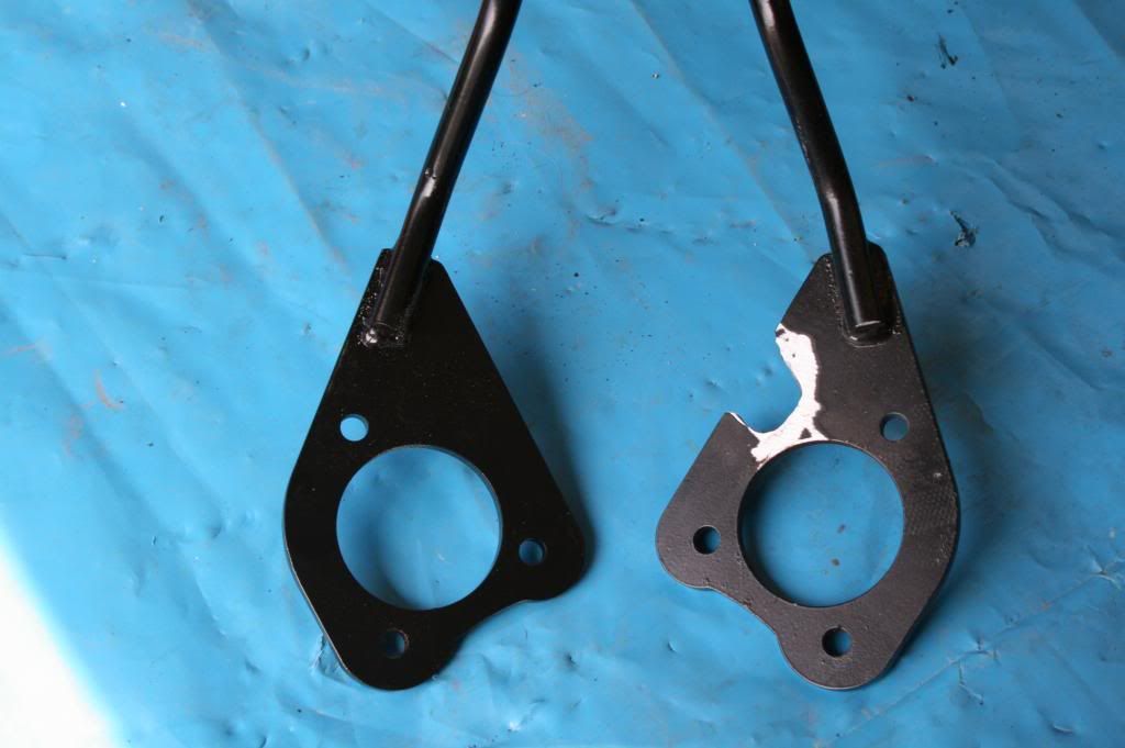 The clearance between this stay and the tyre is 12mm and, for aesthetic reasons, this is the clearance I set out to achieve on the other 6 stays. The front wheel rearward stay and the rear wheel forward stay are located with a single bolt shared with the brake caliper upper attachment. I'm assuming my '99 Mk 2 S has bigger calipers than the stays were designed for. If I attached them using the holes pre-drilled, they stuck up 32mm above the tyres. So, another hole is required and a bit of grinding needed to achieve 12mm at the correct angle. 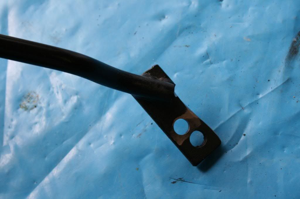 The rear wheel rearward stay again comes pre-drilled. The theory is that a lug on the rear upright is drilled to accommodate the stay. Unfortunately, on mine, no lug, only the ABS mount. 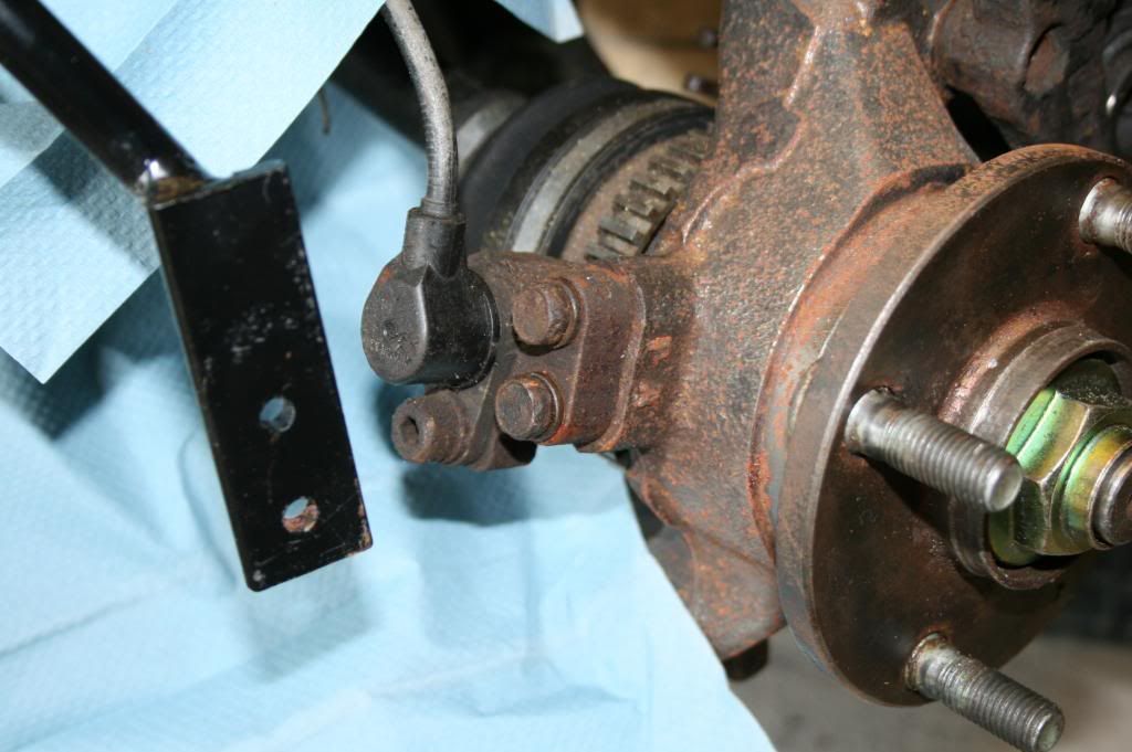 The simple solution is to knock up a bracket to secure the stay using the ABS bolt holes. Except I didn't find it so simple. I found it quite difficult to envisage the geometry required; my ineptitude would have brought tears to the eyes of my engineering drawing tutor were it not for the fact that he would now be well over a hundred. In the end I had to trial fit a bracket, then another, then another, then another... 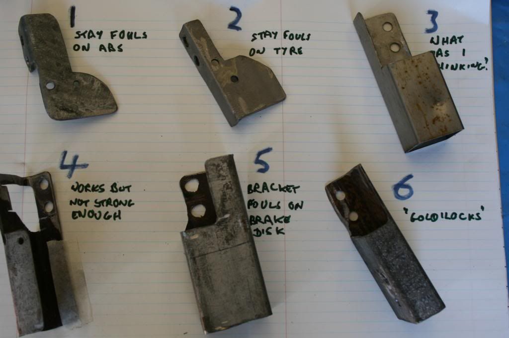 The one that worked came out of a garden gate that my neighbour was discarding. 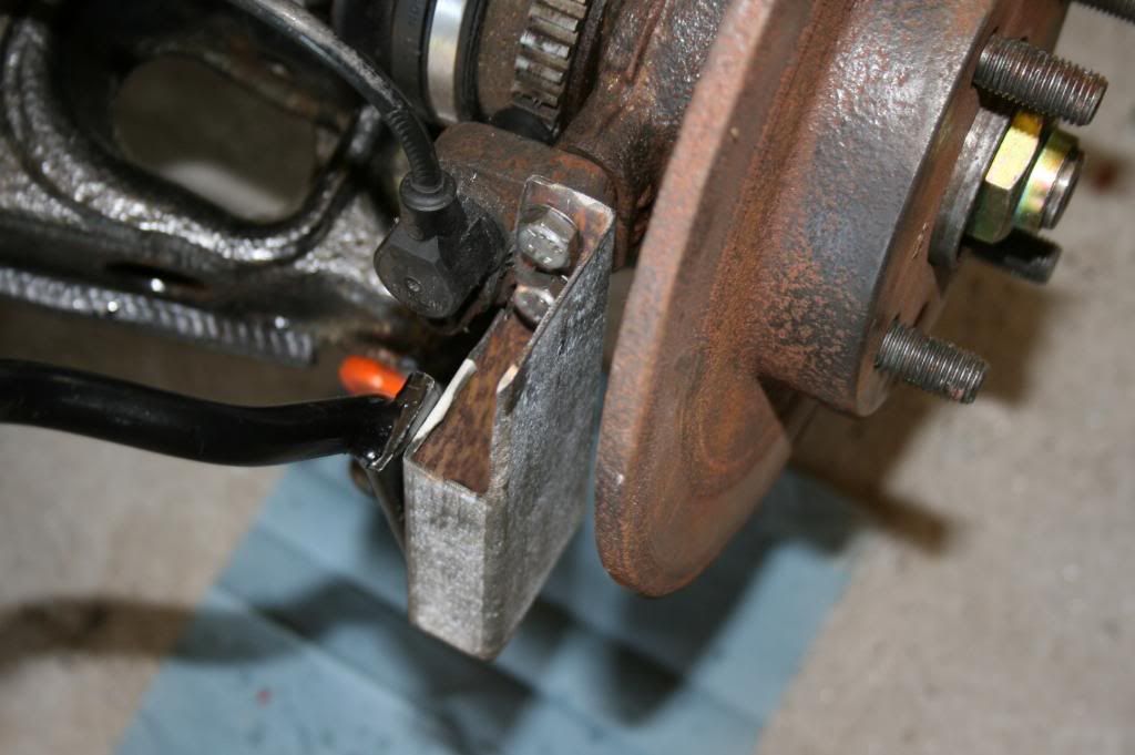 So far so good. Next step is to take all the stays off, paint 'em up and start the re-build of the 4 corners. |
|
|
|
Post by gwnwar on Jul 25, 2013 18:08:31 GMT
The calipers are same size the brackets are different.. Are you going to weld up the hole that is not used
and smooth out for looks and strength.. Are you dropping a sleeve into the rear bracket you made (nice job)
to prevent the squeezing together of the sides.. When finished you might put a drawing with measurements for others to use..
|
|
|
|
Post by nitram on Jul 29, 2013 16:07:41 GMT
I'm not going to weld up the hole. I'm the bloke who doesn't do welding. That part of the stay is well concealed inside the wheel, behind the caliper. I don't believe strength is affected as the bolt goes through the upper hole; it would be a different kettle of fish if the bottom hole was used. No need for a sleeve. The stay only bolts on to the inner face of the rectangular section so there is no sqeezing effect. The actual requirement for the bracket is simple: 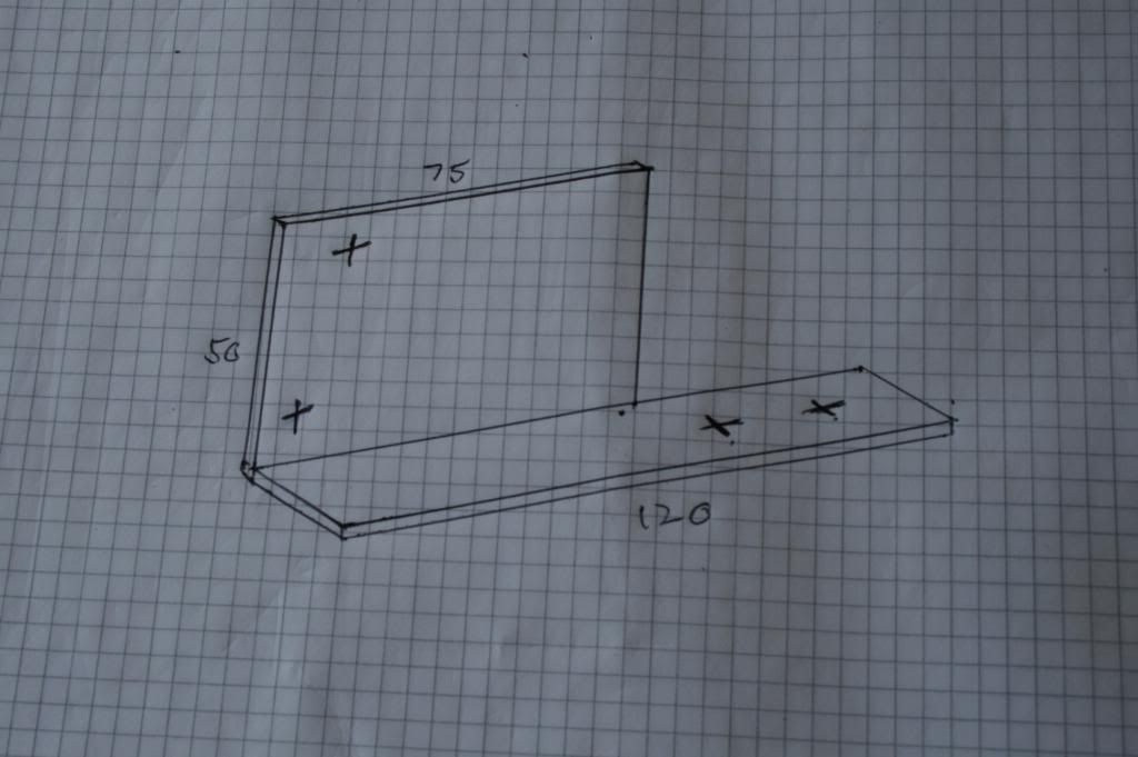 If it were being manufactured out of 5 or 6 mm angle iron, this is all that is required. However, I did not have any of this thickness; the angle iron I had was too flimsy. Hence the somewhat more complicated rectangular section bracket made from the neighbour's redundant gate. |
|
|
|
Post by scooby1929 on Jul 29, 2013 20:29:58 GMT
I could send you a length of 5mm angle iron over
|
|