|
|
Post by tojeiro on Jan 27, 2017 22:49:43 GMT
Been a busy few weeks since Christmas with overseas travel which means I have not got as much done as I would have liked, however, have made some progress and boosted Amazon and eBay profits with all the bits and bobs I have bought. Doing the brake and fuel pipes has seemed to be a never ending task, although maybe my own worst enemy as I first spent quite a bit of time making templates out of the copper pipe that comes with the kit before bending the Kunifer pipe that I bought at the NEC classic. Using the Laser brake flare tool that I bought at the same show and in my opinion it has made perfectly good flares for the £30 quid that I paid. Switched the new fuel lines to the chassis after advice from Snowbird and Stuart. Tried to find triple pipe clips without much success so came up with a alternative which keeps everything compact but separate and solid. The dual 8mm pipe clips are on a couple of pounds and the plastic spacers 69p. 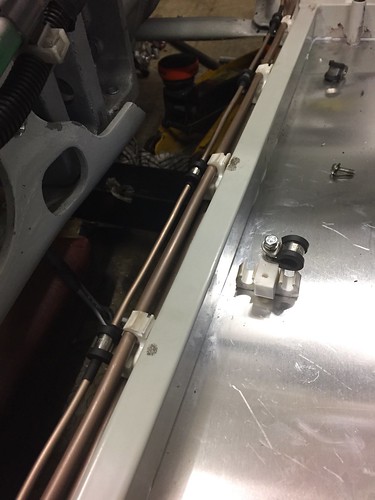 by -Tojeiro 74- by -Tojeiro 74-Only needs one rivet nut per clip in the chassis and the screws have been put in with plenty of threadlock. As quite a few bits have made their way on onto the car a found a new use for some spare shelving (and the wife's clingfilm) 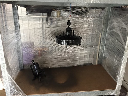 by -Tojeiro 74- by -Tojeiro 74- |
|
|
|
Post by tojeiro on Jan 27, 2017 23:16:00 GMT
Looked at a few build threads to see what others have done to address the gap between clutch master cylinder and bulkhead. 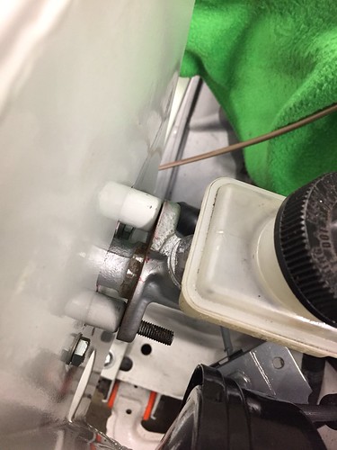 by -Tojeiro 74- by -Tojeiro 74-Tried a piece of 15mm thick high density black foam but it was only just about thick enough and not very weather tight. Final design uses a £3 jack pad that I drilled and routered down to size leaving about 1mm for compression. 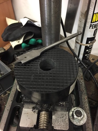 by -Tojeiro 74- by -Tojeiro 74-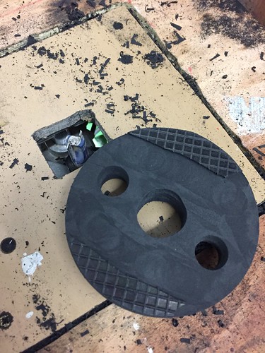 by -Tojeiro 74- by -Tojeiro 74-And fitted with new Clutch Master and Slave cylinders (more pennies). The donor ones still looked pretty rough after cleaning and decided to go all new rather than just change out the seals. I profiled the pad with the router also but you can cut it with a saw quite easily. Used a thin film of tigerseal on bulkhead side to make perfect seal. Run out of p-clips so haven't finished the lines yet (another ebay order sent) 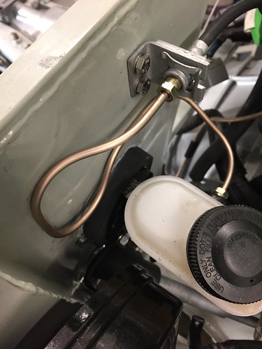 by -Tojeiro 74- by -Tojeiro 74-I notice from some posts that bleeding the clutch has been tough for some on here and also on other Mx5 forums. I used my easibleed kit in combination with the cap from the old master cylinder which I drilled a hole in to suit the easibleed pipe (note: Mx5 size caps are not included in the kit) Bled perfectly in about 5 secs. Locked of the bleed nipple, jacked the back of the car up and checked that I have a working clutch and gearbox, first feeling of progress  |
|
|
|
Post by tojeiro on Jan 27, 2017 23:25:40 GMT
Only noticed once I put it all together that the new cap states DOT3. I know we need a DOT 4 sticker for IVA, but should I get a new cap also or just buff off the 3 on the raised text ? If I had spotted earlier I would have drilled this one for the easibleed and kept the original.
|
|
|
|
Post by tojeiro on Jan 28, 2017 10:09:35 GMT
Solved the cap issue by taking the dog for a walk.
As I came back to the house I walked past my other sitting MX5 in the driveway, so will just swap the caps over, I am sure MOT man does not read the plastic cap.
|
|
|
|
Post by tojeiro on Jan 29, 2017 0:25:50 GMT
Sticking with the brake focus at the moment I rebuilt both back calipers with new pistons and seals kits. I actually refurbed the caliper bodies some time ago but hadn't got round to fitting the new bits. Went with a subtle dark silver high temp finish, actually looks darker here in the photo. 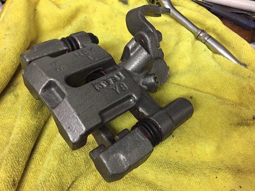 by -Tojeiro 74- by -Tojeiro 74-Main reason for finishing the caliper rebuild was to fit the handbrake cables. More new parts here as I had to basically destroy the originals to get them off the donor. Made up some brackets which I bolted through some existing holes in each side of the rear subframe. After I bit of gentle manipulation both are now mounted securely and clear of other parts. 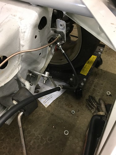 by -Tojeiro 74- by -Tojeiro 74-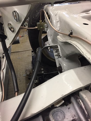 by -Tojeiro 74- by -Tojeiro 74- |
|
|
|
Post by tojeiro on Jan 30, 2017 22:42:48 GMT
So bit more progress, nothing too exciting but felt I have made a committed step forwards since the frame is now bolted down on the PPF. Until now its just been resting on top so that I could lift up and down with my engine hoist to ease access to stuff and make sure none of the pipework runs fixed to the frame foul the PPF or engine. 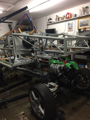 by -Tojeiro 74- by -Tojeiro 74-On an earlier post I mentioned that the kit bolts seemed too short with the Nylocs provided, I ordered some same grade replacements that have plenty of thread. 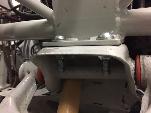 by -Tojeiro 74- by -Tojeiro 74-Had to pack up the rear to avoid the common issue of rear sub frame contact. 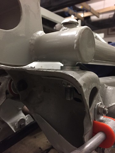 by -Tojeiro 74- by -Tojeiro 74-Drilled my first ever rectangular(ish) hole. Please believe me it looks straight in person. Still have a litre of the correct chassis colour paint so touched up the edges after checking the cable clip fits. 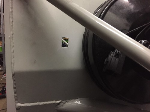 by -Tojeiro 74- by -Tojeiro 74-Repainted the steering column while the paint was open, with originally parts refurb I had gone for a gloss black finish but decided now to go with the light grey to match the chassis and pedals. 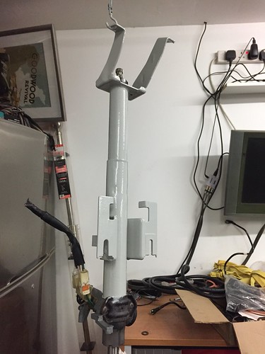 by -Tojeiro 74- by -Tojeiro 74-Next job is a major tidy up in the garage (quite ashamed) and a clean of the frame and PPF before doing any other work. Bought a small yellow touch up paint so going to torque up and mark bolts that not coming off again (hopefully) while access is still easy. Setting myself an aggressive target to have the engine started before end of Feb so lots to do over the next three weeks. Should it somehow blow itself up then I can have an excuse for a Rocketeer V6  March is bonus payment time at work so if I don't break it quickly my wife will spend it on landscaping the garden that I am currently neglecting. |
|
|
|
Post by john on Feb 2, 2017 17:27:47 GMT
Great progress mate some good stuff, sorry about not logging in and seeing the message in time but like your solution.
Looks a nice tidy build I think engine running on next few weeks is possible.
|
|
|
|
Post by tojeiro on Feb 9, 2017 0:25:31 GMT
Quite a bit of progress last weekend, wife was out for the day so had full 8hrs in the garage. - Front brakes rebuilt with new seals, pistons, etc.
- Front flexi lines fitted with connection brackets
- Fuel tank temporarily fitted (going for custom tank to maximise boot space)
- Rubber fuel lines connected
- Steering column fitted
- Vacuum Cooling water pipework 80% done
- Coolant reroute done (looking for confirmation below that this is correct flow path)
- Loom laid out and most engine connections done
New resulting purchases
- 2nd set of brake pistons, 1st set was for large size despite being listed for normal brakes (was 6 month ago so no refund)
- Clear plastic tubing for brake and fuel lines at areas of potential contact
- Black plastic conduit for loom
- Some removable cable ties to help figure out cable runs
- New bottom hose (old one did a vanishing act ??)
- 1/8" NPT elbow to repair water pump inlet
- 2 x 42mm exhaust clamps
Target for this week/weekend (on holiday next Monday so might manage Sat or Sunday in the garage)
- Fix water pump inlet (usual copper elbow pipe issue, at least it came out completely)
- Final fit of radiator (paint drying on brackets)
- Finish off engine bay wiring including figuring out where all those small black clips & brackets go
- Connect instrument cluster, ignition, etc
- Find and double check all earth connections
- Charge battery
Fuel lines: Didn't like the first try with flared end on fuel lines so cut it off and soldered on a copper plumbing olives. Pipes sleeved with clear plastic piping, pipes are secure so rubbing contact should not be a risk but thought worthwhile to do. 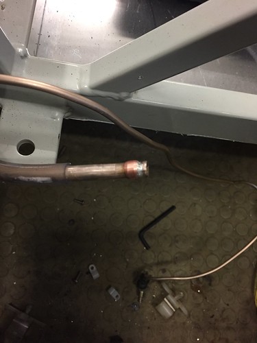 by -Tojeiro 74- by -Tojeiro 74-Replaced engine bay rubber pipe also since I have plenty of extra pipe. Reused original conduit and support under manifold. 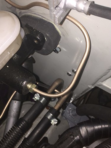 by -Tojeiro 74- by -Tojeiro 74-Brake Pipe supports: Arrived at this solution for flexi brake supports, allows full lock and suspension drop. 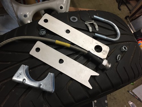 by -Tojeiro 74- by -Tojeiro 74-Bottom plate is filed to matching hex to solve anti rotation requirement Some exterior grade gorilla tape to protect chassis rail. 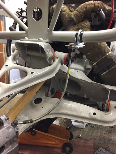 by -Tojeiro 74- by -Tojeiro 74-Water Pump Inlet: Forgot this had happened when I took it apart Had a 1/8 NPT tap in my toolbox so drilled out the housing and tapped the hole ready for a new aluminium elbow fitting ordered from the bay. I have an excellent high temp, high pressure, industrial pipe fitting paste that I will use also to ensure a seal. 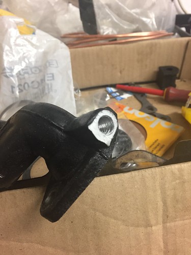 by -Tojeiro 74- by -Tojeiro 74-Steering Column: Couldn't get the column to line up the way I wanted, from other threads it seems like a common issue. I have fitted a temporary support plate, this seemed to solve every issue as immediately I did not have to push, pull or twist the column to get the bolts in. It also sits nice and straight with this plate extension. Despite this slight extension the column and steering rack splines are still fully located at the pinch areas due to the slotted holes on column. 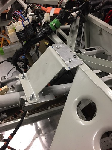 by -Tojeiro 74- by -Tojeiro 74-I don't have any seats at the moment to this is just temporary to save me bending stuff that I might need to bend again later to suite driving position. If needed I will make up an all new column support bracket to match this set-up without needing the extra plate. Coolant reroute: Is this flow path correct ?? 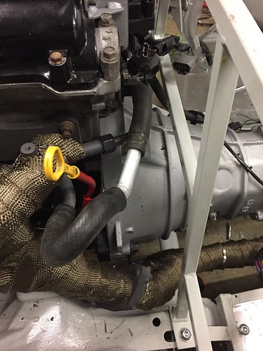 by -Tojeiro 74- by -Tojeiro 74-I cut one of the pipes in half and used a bit of pipe from the side of the heater matrix (something free for once), need to buy some extra hose clips though. Got some new stainless rocker cover bolts to replace those tatty ones |
|
|
|
Post by gwnwar on Feb 9, 2017 6:55:12 GMT
Nice work so far.. Your water is really not a reroute it is just a connection of A to B. Nicely done though.. For a real reroute see.. revlimiter.net/blog/2011/05/coolant-re-route-1/ part 2 click on bottom of page. I was looking at your top front control arms inner long bolt.. With your new bushing do there instructions say not to use the large washers under the head of bolt and nut like an OEM set up??? |
|
|
|
Post by R2S on Feb 9, 2017 8:43:41 GMT
Great to see someone is making some real steps forward, not sure if you've picked it up but you may have to do more tapping for the elbow as the NPT (tapered thread) fitting may have the elbow at the wrong position (I got mine to line up by using a scrap piece of ali, drilling hole then making out position needed before measuring depth of thread I also used ptfe on mine but realise this may need a revisit if not water tight but Im pretty confident).
Despite looking at the u clamp route for the front brake bracket I stuck with my box section as I plan to use it to fix lining.
Having planned to run my brake pipes in clear plastic I simply count get the metal to run inside for more than a couple of foot so rather than waste time I left out off (I tried lubricating with WD40 but this didn't help much). Love the idea of the soldered olives hadn't thought of thought and was struggling to come up with a solution for my rubber pipe connection to the originals under the bonnet.
On the steering rack I notice the current Replicar build manual has the spacers (for the brake and clutch) on the inside of cockpit rather than engine side (wish Id done that as Im now having pedal clearance issues).
On gwnwars point about the large washer it looks like your bush sleeves are narrower than the outside edge of the upper arm and if so using it would simply cause the arm to bind.
Just off to look at guidance on radiator fitting, I seem to recall the level of top is important, so let us know how this goes.
|
|
|
|
Post by tojeiro on Feb 9, 2017 9:56:16 GMT
Thanks for the feedback guys.
Hopefully I am understanding the bush question correctly.
I had and initial issue with axial binding but got some 1mm stainless washers at the recent NEC Classic Car show which are the same diameter as crush tube. This basically adds 1mm to the crush tube and ensures that the clamping force is on the crush tube and not binding on the bush.
With this mod all my wishbones can be moved up with a push using just a couple of fingers and drop under their own weight, where before you had to push really hard with a lot of force to overcome the stiction.
Could be my 2 coat wishbone painting added 1 or 2mm to bush area nesscitating the extra washer.
There was nothing specific in the instructions about these top arms, I used the washers supplied with the bushes for each arm with my extra modification.
You obviously cannot see the thin washer but there is definitely no binding on the bush face. These are two piece bushes so without the thrust washer they could work themselves out.
Long term I may go back to rubber bushes but budget was spiralling so using these for the moment as the originals were totally shot.
|
|
|
|
Post by R2S on Feb 9, 2017 13:38:36 GMT
Providing neoprene cant get past washer, and int doesn't look like it can most important thing is that washer is bearing on crush tube and not the neoprene (but you already probably know that). I fitted larger washer as my crush tubes extend beyond bush and flange of upper arms (which were powder coated).  |
|
|
|
Post by gwnwar on Feb 9, 2017 22:09:34 GMT
R2S.. Like your fix with the added small washers then large one..
|
|
|
|
Post by Fin on Feb 9, 2017 22:24:14 GMT
Providing neoprene cant get past washer, and int doesn't look like it can most important thing is that washer is bearing on crush tube and not the neoprene (but you already probably know that). I fitted larger washer as my crush tubes extend beyond bush and flange of upper arms (which were powder coated).  Can I ask what diameter the dampers are on your coilovers as you've not had to cut the wishbones and fit the provided bananas? My new ones are narrower than the donors, but it still looks as though I have to extend the A opening so they mount top and bottom |
|
|
|
Post by Fin on Feb 10, 2017 11:07:52 GMT
Apologies if this posts twice, but what diameter are the dampers above. They fit nicely through the A frame wishbone without interference, and without needing to cut out the cross piece and fit the bananas. My new ones don't.
That said, I note the wishbone is above horizontal at the wheel, and so pitched towards the chassis. Maybe my chassis is chocked too high and so affecting this?
|
|