|
|
Post by stevednorris on Mar 13, 2018 16:33:48 GMT
|
|
|
|
Post by tojeiro on Mar 13, 2018 22:35:05 GMT
Cheers Steve, looks like simplest solution, I had not thought about being able to convert the cap.
|
|
|
|
Post by tojeiro on Mar 16, 2018 18:10:32 GMT
Arrrghh, electrical woes continue.
Got everything plugged back in for final check before finish fitting my under dash kick plates in place. All my warning lights are working perfectly but big issues still with my Proled speedo.
I never really got this properly working earlier and had just put it off until the rest of the wiring was sorted and working. Spent several hours now checking and rechecking diagrams and wiring connections, finally have up and sent below to Digital Speedo where I bought the dial.
Dear Sir,
I purchased a Smiths Proled gauge from you at the Lancaster Classic car show in Nov 17 for my 1999 MX5 based kit car.
I have now reached the build stage where I am finalising dash wiring and have the following issues
1. Proled lights up on ignition then goes off on start. Multimeter check confirms constant voltage across green 12v wire during start.
2. Occasionally the dial freezes on sweep and ignition needs to be turned off and back on again.
3. Temp shows max regardless of settling chosen I set-up menu (currently on EU coolant) ohm reading 845 (mildly warm)
4. Fuel shows empty despite 70 ohms reading at tank sensor and feed wire to gauge
I have double checked all wiring and cross checked with other builders on the kit car forum.
I have good earth connections (all checked) and even ran a 2nd direct grounding wire to -battery terminal as guarantee for testing.
Car operates runs and all other electrical operating fine, all warning lights on dash (same loom/feeds) illuminate or extinguish as expected.
I have expected resistance values from Fuel tank sensor and Temperature sensors and original Madza instrument cluster was reading correctly before changing to the Proled.
Ignoring oil pressure reading as currently Mazda pressure switch while I wait on a pressure sender, switch is working as my warning light goes out on start.
Your advice would be appreciated - fault in Pro-LED unit or suggestions.
While I wait on a reply I am going to wire up the original dash plugs to recheck everything still working as it was before.
|
|
|
|
Post by tojeiro on Mar 17, 2018 0:57:40 GMT
Video links sent to Digital Speedos in case anyone has ideas.
|
|
Deleted
Deleted Member
Posts: 0
|
Post by Deleted on Mar 17, 2018 15:37:18 GMT
I had a full set of Smiths Flight gauges in my Westfield and had several failures very quickly. I ended up speaking to the MD who helped me out with replacement bits, I started with their technical bloke but he lost interest in fixing my issues. If your supplier isn't quick on getting a fix I would suggest you try direct contact. They are here www.caigauge.com/ as they split from the larger Smiths company a long time ago. |
|
|
|
Post by tojeiro on Mar 17, 2018 23:55:24 GMT
cheers westie, I saw some other forum posts suggesting that CAI had been helpful in resolving issues but good to hear the same first hand.
I felt it right to contact Digital Speedos first and maybe they have some idea (I am not ruling out some electrical issue on my donor). if I don't get a reply I will contact CAI direct.
As I have everything connected with multiple connectors I can easily check the signals / volts / etc that are being received from the sensors right at the gauge
I have checked and rechecked everything at least twice but if I get some time tomorrow I will make some jumper wires and connect again one wire at a time in case some signal conflict is causing the cutting out symptom.
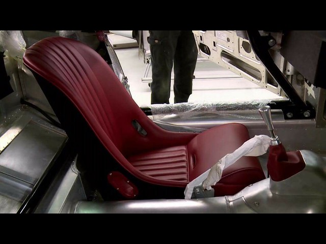
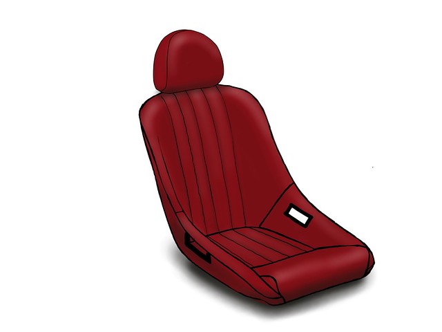
To cheer myself up I have been getting my seat designs finalised with Intatrim, took the inspiration from the Inside Jaguar e-type program
 Untitled by Scott Graham, on Flickr Untitled by Scott Graham, on Flickr
 Untitled by Scott Graham, on Flickr Untitled by Scott Graham, on Flickr
Lines look dark but stitching and piping will be same colour as leather, going with a deep red burgundy leather from Wildman & Bugby. Going to get my order placed at the end of the month - annual bonus time so easier to get passed through the household finances especially since I need to order a matching hide for dash, rear bulkhead and door cards.
|
|
|
|
Post by tojeiro on Mar 18, 2018 21:49:41 GMT
Connected up the original dash again using minimum wires and all is working again. Ran the car up to temperature and radiator fan kicks in properly. The positive I suppose is that I am certain my wiring is right but now really looks like an issue with the gauge which could mean some weeks delay. 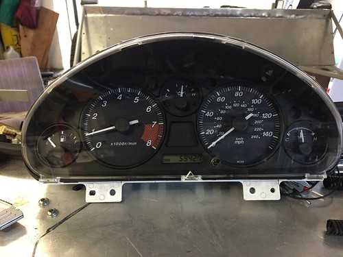 by -Tojeiro 74- by -Tojeiro 74-Since I can access all my plugs without removing the dash moulding I decided to work on finalising the position and kick panels. I originally had the dash hard against the rails on the frame but actually this meant quite a gap between dash panel and steering cowl. Having noticed I was also a bit off centre I decided to move the dash by about 3/4” forward and centre it over the column. This meant extending my kick panel which was a pain I wanted to skip but actually was quite quick. Now have about 1/4” gap which will be filled with my trimmed dash panel. 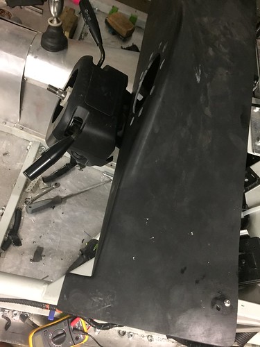 by -Tojeiro 74- by -Tojeiro 74-On drivers side I made up a lower aluminium cowl to give space for wiring loom plugs. I lined the kick panels with 3mm self adhesive foam to avoid any chaffing risk and dampen any noise when driving. Outside will be trimmed in leather or vinyl depending on how much I have left after finishing other important parts.  by -Tojeiro 74- by -Tojeiro 74-I have bought some proper acoustic sheets for the floor and transmission tunnel. A frustrating week but at least I feel I made some progress. |
|
|
|
Post by tojeiro on Mar 20, 2018 19:48:43 GMT
Been in touch with CAI and gauge has been posted back for testing/repair.
Since that is away I have started working on my aluminium fuel tank plans.
Does anyone have any info if there is a minimum height / slope above the max fuel level the filler cap mounting should be?
I am planning to place the tank in the gap between the rear subframe and body with a flat style filler cap on the side of the body, therefore not as much of a rise compared to a top mounted filler cap like others.
Nearly have basic plan and model finished, will be subcontracting the fabrication.
|
|
|
|
Post by tojeiro on Mar 22, 2018 19:51:54 GMT
First mock up fitted quite well, going to extend the width a little to gain some extra capacity, currently works out about 38 litres. I am OK even with it as is since I don’t expect many long journeys on a roofless car without regular stops but have plenty of room so will extend by 100mm each side. 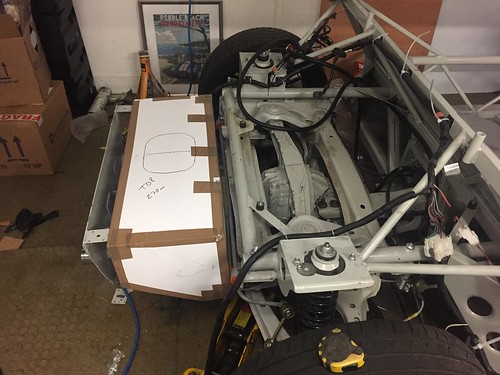 by -Tojeiro 74- by -Tojeiro 74-I have made some 3d drawings which will go to the fabricator, he is going to add the baffle plates to avoid sloshing and fuel starvation, although natural shape helps keep most of the fuel in the right place. Fuel pump will be mounted at the side and not in the middle. Certainly opens up space in boot which was the main plan. 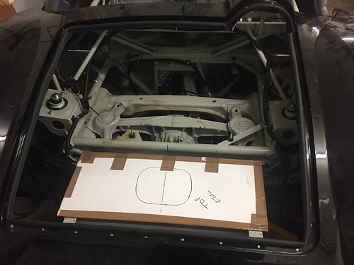 by -Tojeiro 74- by -Tojeiro 74-Tank will sit inside an aluminium box to protect it from road rash and heat from exhaust, have about 2” gap above exhaust, will add some heat reflecting sheet over exhuast area. |
|
|
|
Post by cricky on Mar 25, 2018 9:31:23 GMT
First mock up fitted quite well, going to extend the width a little to gain some extra capacity, currently works out about 38 litres. I am OK even with it as is since I don’t expect many long journeys on a roofless car without regular stops but have plenty of room so will extend by 100mm each side.  by -Tojeiro 74- by -Tojeiro 74-I have made some 3d drawings which will go to the fabricator, he is going to add the baffle plates to avoid sloshing and fuel starvation, although natural shape helps keep most of the fuel in the right place. Fuel pump will be mounted at the side and not in the middle. Certainly opens up space in boot which was the main plan.  by -Tojeiro 74- by -Tojeiro 74-Tank will sit inside an aluminium box to protect it from road rash and heat from exhaust, have about 2” gap above exhaust, will add some heat reflecting sheet over exhuast area. Doesn’t the tank or fuel cell have to sit forward of the rear axle to prevent explosion in the setting of a rear impact? |
|
Deleted
Deleted Member
Posts: 0
|
Post by Deleted on Mar 25, 2018 12:42:47 GMT
Tank should be fine there, just need to make sure nothing sharp could puncture it if hit from rear. The tank in my Westy is right at the back of the car.
|
|
|
|
Post by tojeiro on Apr 13, 2018 23:47:33 GMT
Wee update, gauge is at CAI for checking, good news is that since it is there as well as checking the board the gauge will be calibrated to the stock Mazda fuel and coolant sensor inputs while they have it on the test bench. Got a very helpful engineer down there that called me to discuss all possible resasons for the issues I am facing, if gauge test comes back OK he offer to help with some suggested wiring alterations. Meantime, in between travel with work I have managed a major milestone getting my door hinge support plates bonded onto the body, no pictures yet, going to get the doors fitted soon then post the complete process, used a Methyl methacrylate (MMA) adhesive, and could now pick the whole body up using the bonded bracket so happy I have plenty support for the doors. 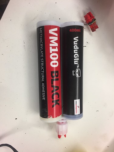 by -Tojeiro 74- by -Tojeiro 74-Regards fuel tank I decided in the end to move it back under the rear bulkhead as I can have space for tank and battery, currently working on moulds for my fibreglass boot tray. Need to get this moulded and installed so that I can check my poly board fuel tank model still fits before sending sizes to the fabricator. |
|
|
|
Post by tojeiro on Apr 25, 2018 0:00:30 GMT
As per previous posts in my build blog I was a bit determined to have internal door hinges. I even measured up some options for cobra style hinges at Stoneleigh before I placed the order for the kit. This in the 3rd version of the hinge and one that I am happy with regards strength and operation, later I may get some billet aluminium hinges made up replicating the same dimensions. 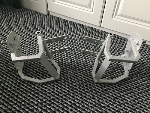 by -Tojeiro 74- by -Tojeiro 74-Mounting to the body is in the form of perforated plate formed to the shape of the body, it sits tight against my aluminium angle bonded at the base of the body. 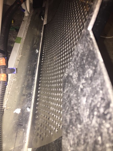 by -Tojeiro 74- by -Tojeiro 74-Onto this I welded some 3mm stainless plate with studs to bolt the hinge bracket to. 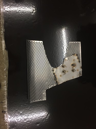 by -Tojeiro 74- by -Tojeiro 74-I then bonded on with VM100 Methyl Methacrylate adhesive. This is a 2 pack adhesive, expensive at £33 a pack but is unbelievable for bonding almost anything to fibreglass. Bit of a nervous time doing the bonding, you only get about 10mins from mixing to solid and once on its never coming back off. 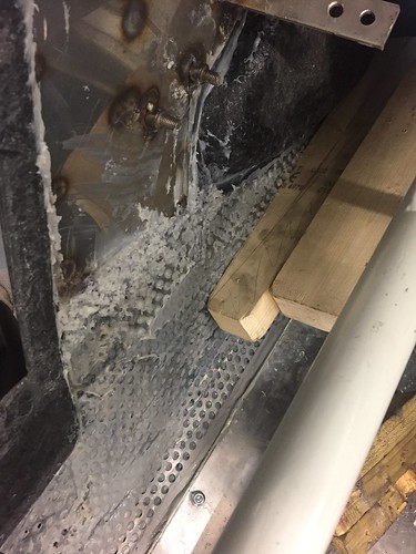 by -Tojeiro 74- by -Tojeiro 74-I could actually lift up the whole body from the bonded on bracket now without any concern. Used a whole tube on each door which now seems like complete overkill but didn't want the doors falling off or coming loose. The welded on hinge mounting plate and screws are all stainless, all internal body surfaces and bonded in plates and brackets will be getting a coat Raptor stone chip soon but wanted to avoid any corrosion on exposed parts now that they are bonded to the body. The hinge assemble is currently fabricated in steel and is bolted to the mounting plate allowing some adjustment both lateral and longitudinal, there is also some rotational adjustment via the slotted mounting holes I made in the in the door to achieve nice panel gaps. Result is a nice smooth hinge mechanism with solid support For latches I looked at using the MX5 ones I purchased (my donor doors were already sold) but they are quite large and very tight to fit in the door pocket area, Didn't pay very much and got everything including rods, internal pull handles and some nice chrome exterior handles so reckon I get my money back on eBay. In replacement have ordered some Autoloc bear claw hinges from US (with secondary latching for IVA) and will pick them up in May when I am there on business. I bought the US ones as these come with additional lock pin which doesn't seem available in UK. They were also £30 less since I will pick up in US. Will probably add a hidden lock switch somewhere or even use a powered actuator. Might seem a bit pointless on an open car but still rather not have everyone just able to open the door whenever they like. |
|
|
|
Post by tojeiro on Apr 26, 2018 14:34:26 GMT
One wee tip that I used to achieve a nice smooth action and ensure that the hinge barrel and hinge pins were a close fit and parallel. As I don't have a lathe in the garage (not yet anyway  ) I had to come up with another solution to machining the heavy wall pipe that I purchased for making the hinge column. I used 3mm wall as I was welding 3mm steel plate to the pipe and didn't want it bending with the heat. I cut the pipe into 3 sections and the flatted the end best possible with my grinder and file. I then mounted the pipe into my pedestal drill chuck and pressed down (carefully) onto my flat file. The file does skid a little on first couple of presses but after a bit it stabilises and eventually ends up flat, you can feel the drag change is you reach the flat stage. 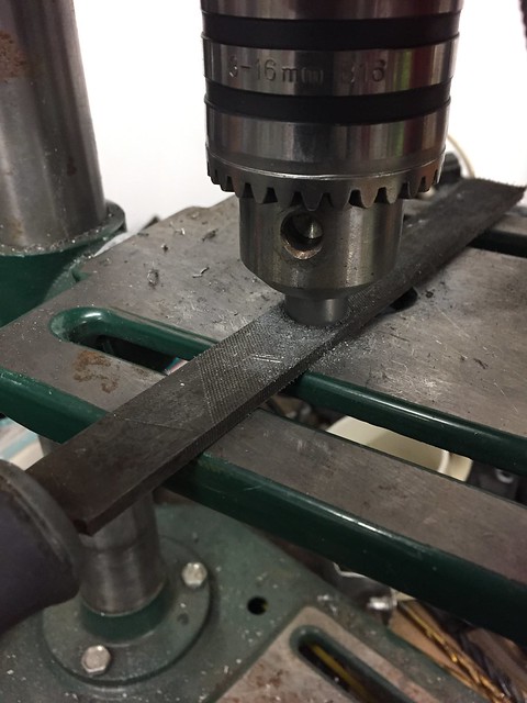 Untitled Untitled by Scott Graham, on Flickr Followed by some wet & dry paper for a better finish. 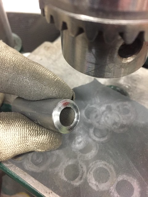 Untitled Untitled by Scott Graham, on Flickr I know that there is a little movement in my pedestal drill chuck but it was still amazing to see how far out my initial hand filing was. I left the long centre piece until last so that I could get the exact length after the short non rotating pieces were welded to the hinge. As you can see in the photo above the centre piece is a close enough fit that it stays in place without the pin in place. For the hinge pin I bought some stainless bar and cut a thread, welded a nut on one end and threaded the other end. Lubricated the pin and bores with that thick red brake grease which I like as it doesn't run. ---------------------------- Just started on some bonnet hinges using the same method. 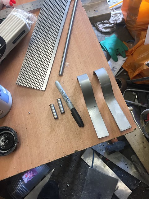 Untitled Untitled by Scott Graham, on Flickr |
|
|
|
Post by tojeiro on Apr 27, 2018 21:37:39 GMT
Managed a few hours to finish my bonnet hinges. 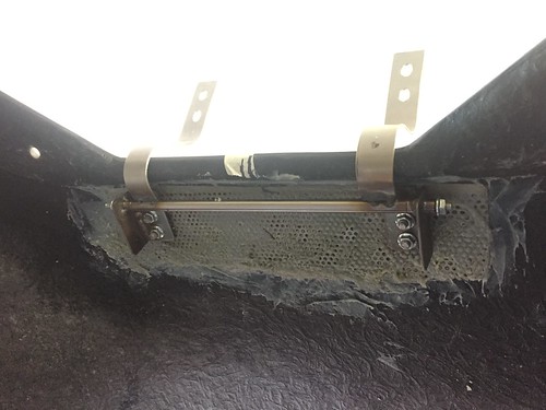 by -Tojeiro 74- by -Tojeiro 74-Have enough clearance that I miss the induction pipe when I close the bonnet. 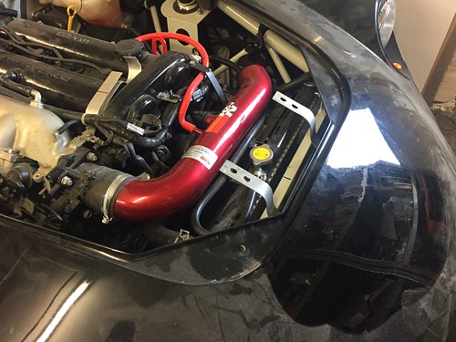 by -Tojeiro 74- by -Tojeiro 74-Going to use Cobra style locks at the scuttle, planning to pick them up with a lot of other shiny bits at Stoneleigh next week. |
|