|
|
Post by ian360 on Feb 11, 2016 16:50:22 GMT
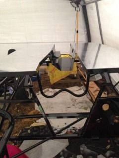
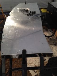
In amongst the cold and windy days and nights since Christmas, have grabbed an odd hour or two here and there and made some slow progress - made slower by the fact that building is a lot more testing than dismantling and painting. Have now cut and riveted the floors into place, only took a couple of goes to feel confident with the lazy tong and it certainly made light work of the job. 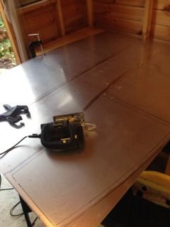
Borrowed some ideas from other threads (thanks Nitram and Yorkie) for running the fuel and brake lines front to back. Made up some brackets, wasn't happy with them, made some more and riv nutted them into place. I didn't think I'd be saying that 12 months ago! 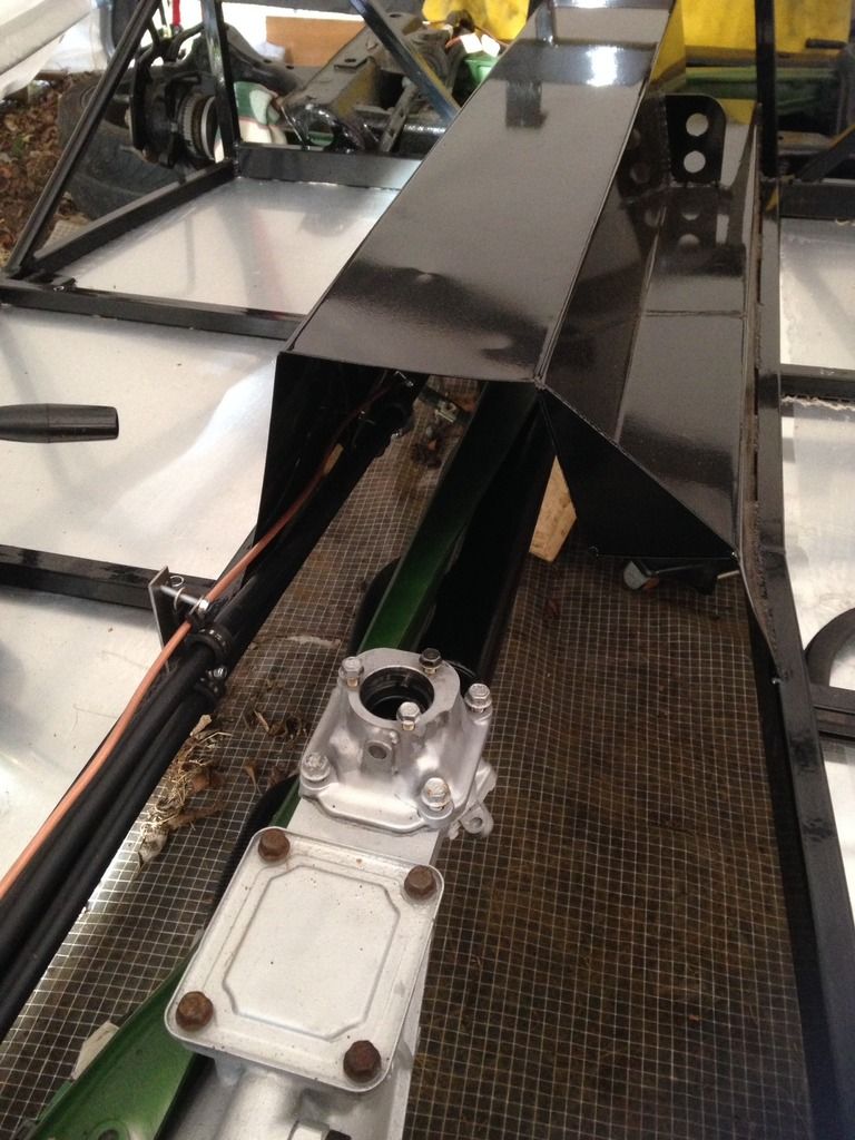
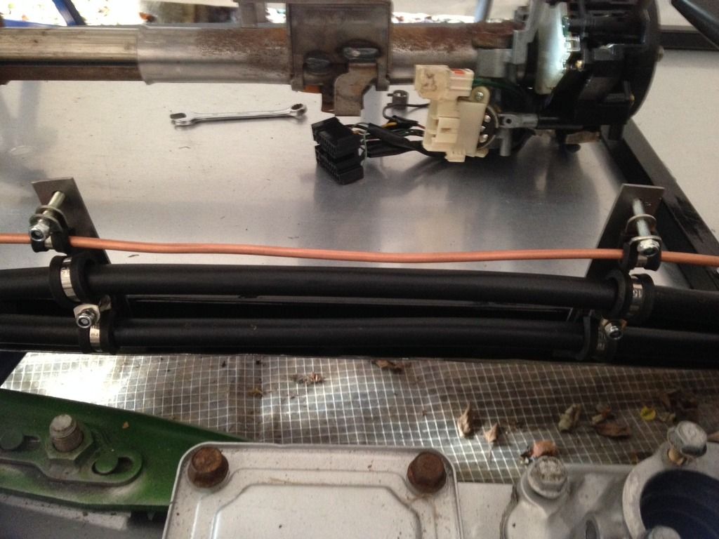
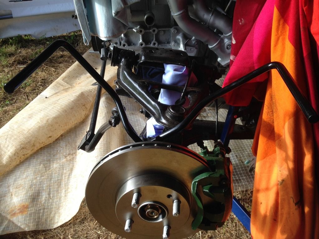
None of the bolts have been tightened yet as want to be absolutely sure everything is in right place. One thing to note, the earlier build threads make reference to the tightness of the tunnel at it's rear exit. I have one of the new frames and as Stuart pointed out on collection the angle at the rear is now slightly wider and makes for a lot more room, so looks very easy now to run things through - hopefully I won't come to regret that comment! Cracked on and fitted the front wing stays, simple enough after cutting out a section to fit around ABS sensor. 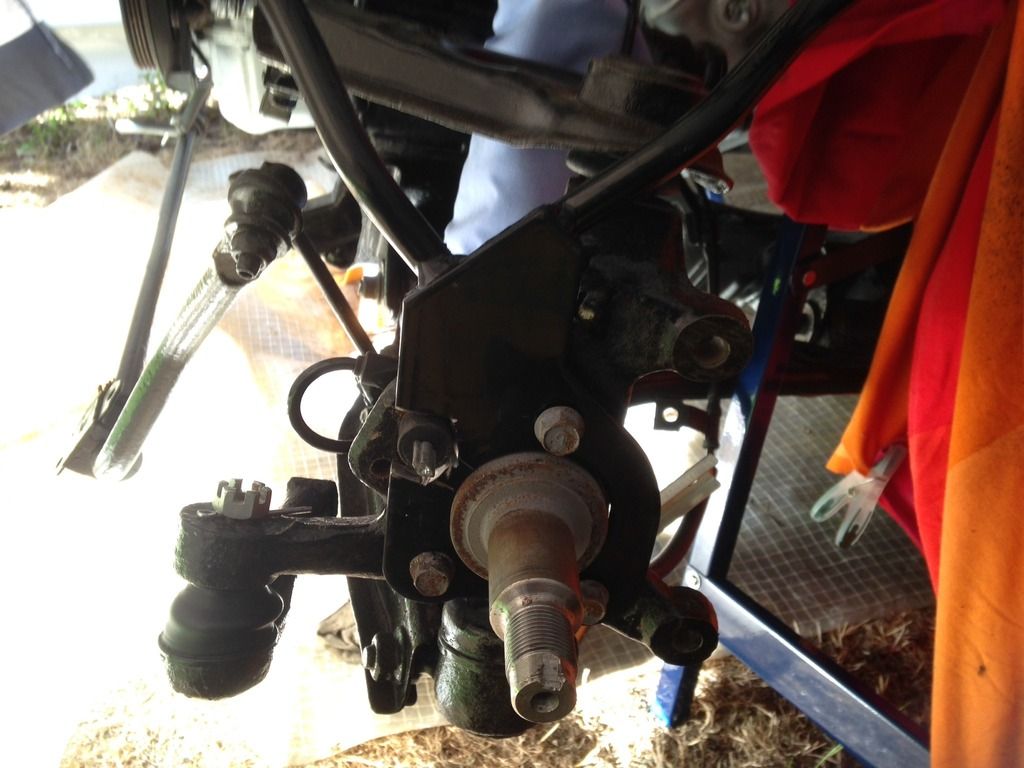 Trial fitted with the brake disc and caliper Trial fitted with the brake disc and caliper
Moved onto the rear and after much deliberation gave up! Partly because by that time it was getting too cold and partly I couldn't figure out how the stays fitted, despite recent posts on the subject of the new all in one version. With the rear ABS sensor I don't think there is room to drill through the carrier, and it will need a bracket fixing. I'll have another play this weekend but does any one recognise this as standard, as the whole shape of the stay just seems wrong when offered up?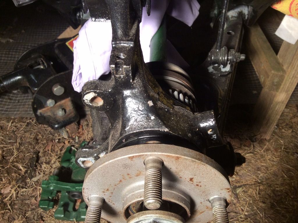 I have the hub bolt undone, the hub itself doesn't want to move but I am thinking it probably isn't necessary anyway? Have dug out the pedals and next plan is to fit them and steering column. Without question this build would be near impossible without all the other threads to refer to, and what better way to pass the winter evenings than reading up on it all?
|
|
|
|
Post by ian360 on Mar 8, 2016 10:36:34 GMT
After a couple of weekends that went from total frustration to a feeling of some accomplishment, an update of what I have been doing. Front stays all complete both sides, had some issues with the rear and after discussion with Stuart it seems ideally the ABS needs removing in order for them to fit as supplied. That means changing brake master cylinder and seemed more trouble than first trying to make the stays fit another way. The first offering shows the problem of the ABS sensor being in the way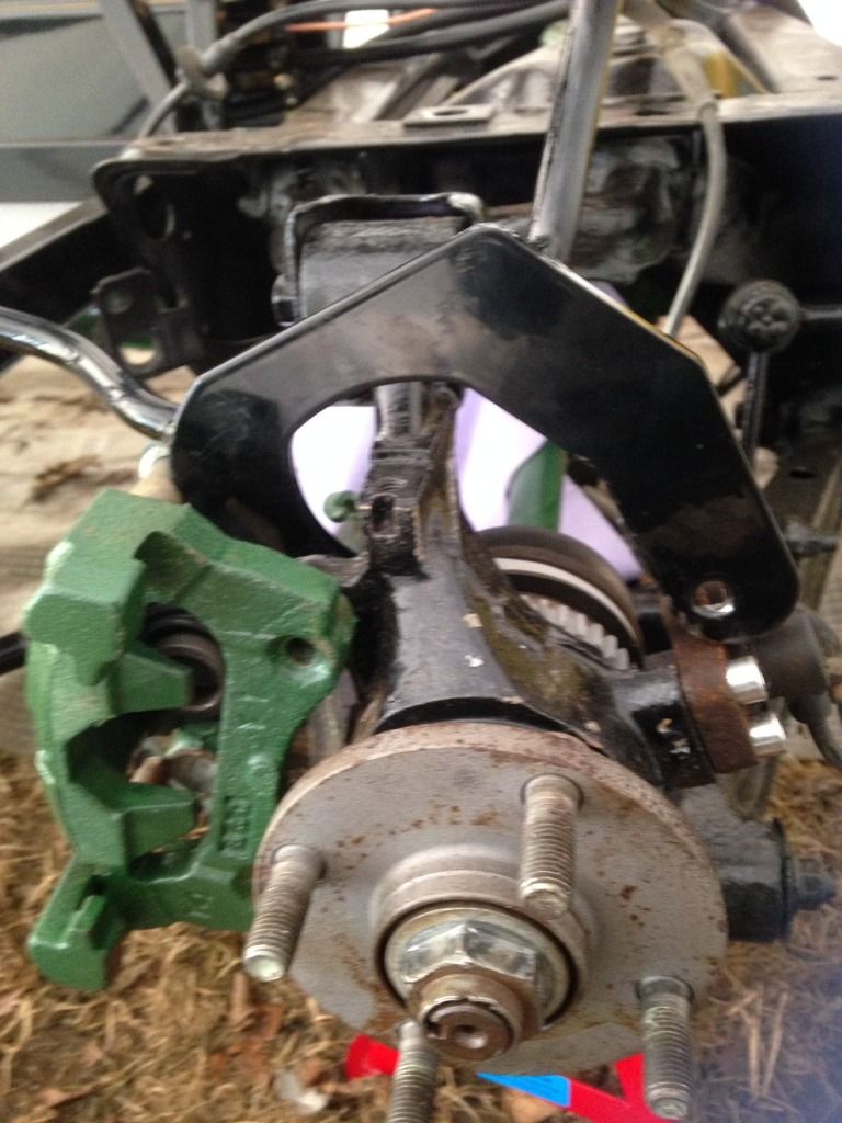 so out with the grinder and took off the lower part of the stay so I have some play on the levelness. Will now need to make some sort of bracket to fit the sensor and back of the stay to hold firmly in place. My first attempt isn't worthy of publishing, need to have another go. Think angle iron is the way to go... 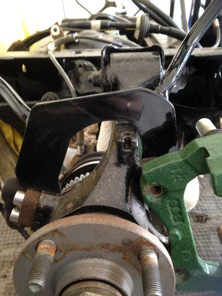
Next plan was to look at the pedals and steering column. Another thread tells of the issues I initially had, and having resolved most of those set about trial fitting. This is where the frustration started - I just couldn't see how it would all fit together with or without spacers, to the point I thought I must have some completely different components to mazda originals! Certainly the old adage of walking away from a problem worked. After taking out some issues with some logs that needed chopping, I went back to the pedals and suddenly everything fell into place! How does that happen? 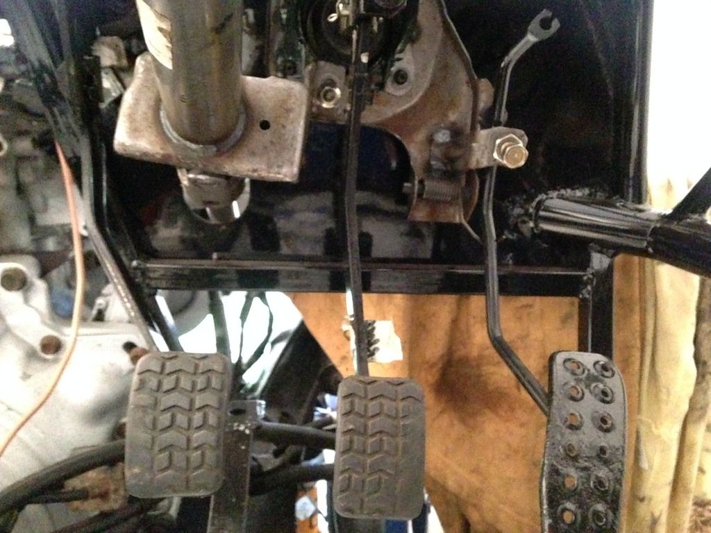
Needed eventually to cut the spacers off the back of the brake pedal and fit on the engine side of the bulkhead to make everything fit. Then took it all off for a lick of paint as wasn't aware so much would be on show. 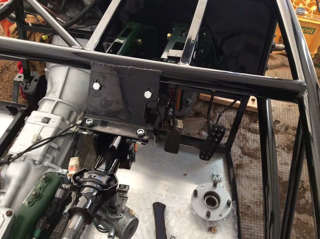
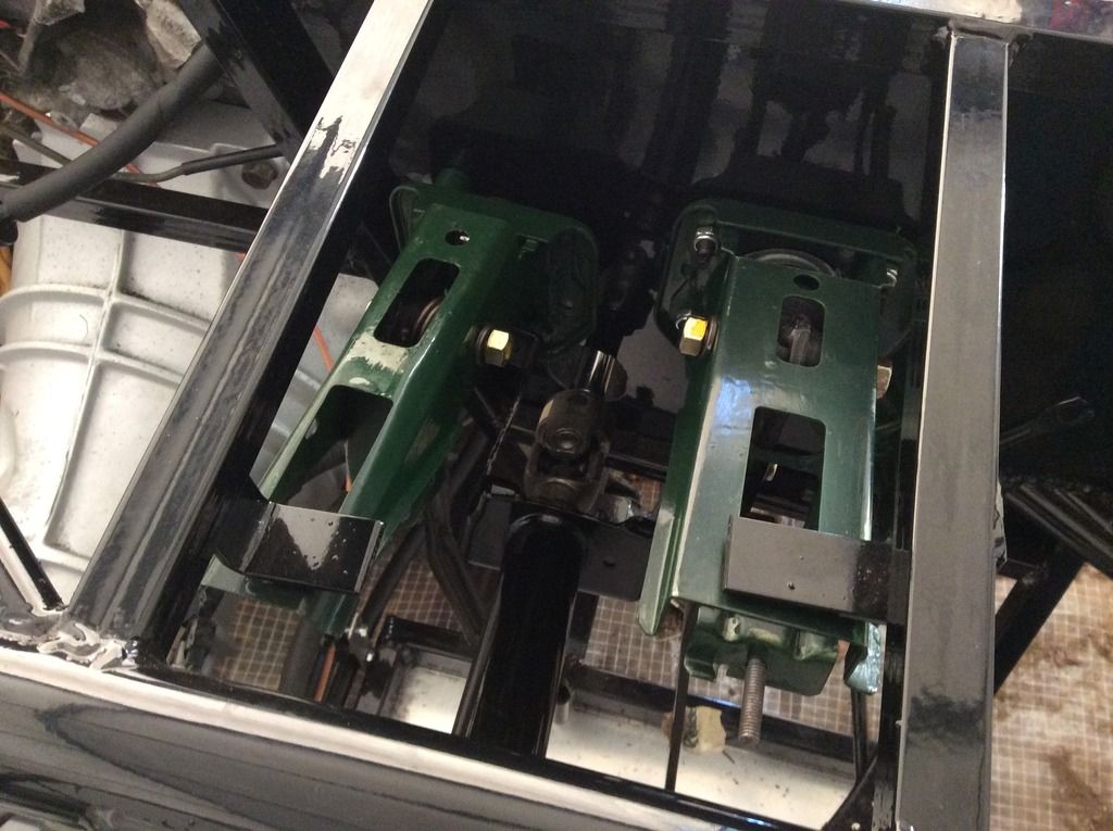
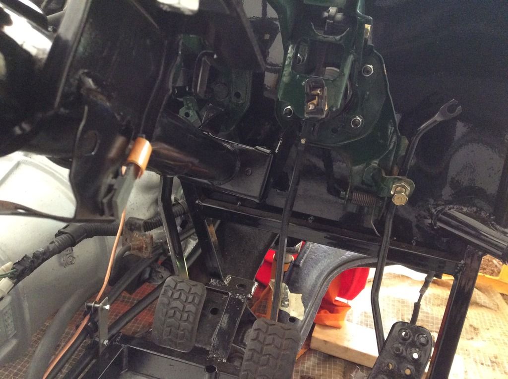
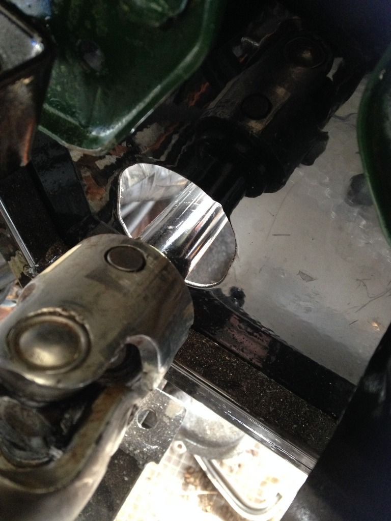
I'm quite pleased with how it all looks and fits, but of course I am happy for anyone to tell me otherwise! I need to take off again to fit the rubber gaiter through the bulkhead, this will need some drilling as no holes there currently. Can anyone give me advise on the best way to fix - I am assuming riv nuts will suffice? Final piece of this jigsaw is connecting it to the steering rack, which at the moment I don't have but that is another story!
Whilst I was feeling in such good achievement mode I cut out the wishbones to allow the shocks to fit 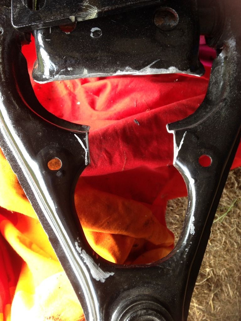
Just need a quick spray to tidy and can bolt on the banana fittings supplied as part of the kit.
Final thing for the weekend was to trial fit the new exhaust system I bought to make sure it did actually sit down the tunnel without fouling. All looks ok so think I am nearly ready to mate the two chassis together.
|
|
|
|
Post by ian360 on Apr 4, 2016 11:20:35 GMT
Update time, have had a busy few weekends making progress.
Having cut the wishbones out, made up and fitted all the suspension and shocks. No real dramas, other than again will have to remove all as need to touch up on some paint work. Lowered the chassis and all the bolt holes lined up without much effort. My original wheels don't fit with the wing stays, so either spacers or new ones needed. Removed the stays so I could put the wheels on and move it out of the garage so I could have a tidy up. Couldn't resist the obligatory picture with the front offered up and seats in place! 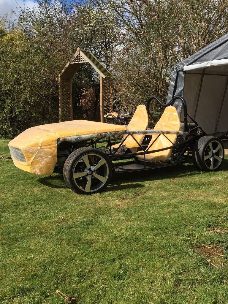
Next challenge was to fit the ABS unit and new brake lines. The bracket for the ABS doesn't have an obvious mounting point on the chassis in the region of where it was on the donor, but a couple of rivnuts and new holes in the bracket sorted it soon enough. Bit of practice with the flaring tool on double flares and felt confident enough to go for the new lines. Happy with the outcome, maybe the lines could be straighter...... 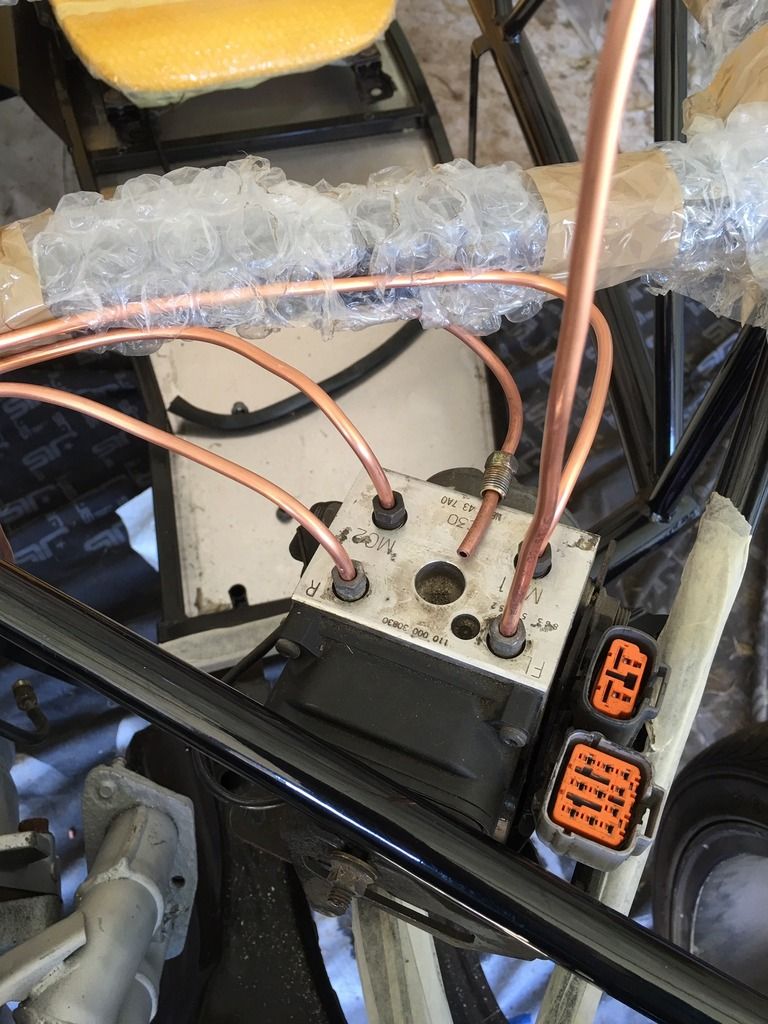
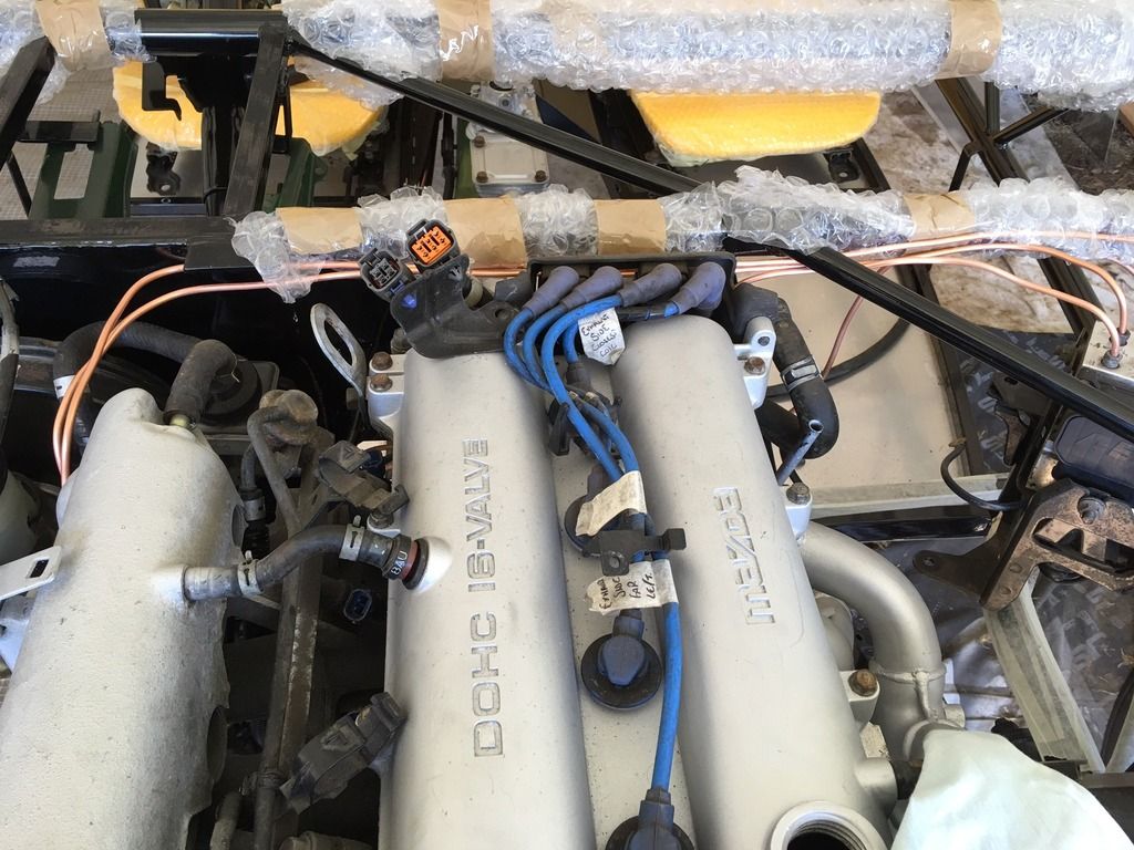 I have the rear line still to do which will have to be in situ, didn't feel ready for that yet! Also need to p-clip all the lines to the frame, but will do that once I split the two again when access will be easier. I have the rear line still to do which will have to be in situ, didn't feel ready for that yet! Also need to p-clip all the lines to the frame, but will do that once I split the two again when access will be easier.
Question please - the line from the clutch m/c heads over the passenger side of the engine bay. From pictures of my breakdown that does appear correct, although I might have bent it a bit since removal! I've seen similar on other builds that it does seem to go in that direction. In order to meet the slave, the flexible pipe has to stretch over the gearbox, and it is tight. Should there be another component in this line somewhere? Hopefully this picture explains better: 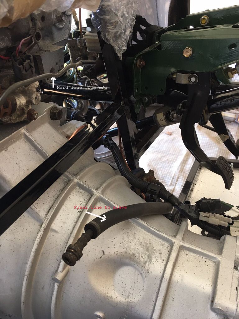
|
|
|
|
Post by gwnwar on Apr 5, 2016 4:57:05 GMT
You might try to make a few different lengths of wood blocks to clamp around the copper lines and slide them to straighten them some..
Clamp 2 pieces of wood together and drill a hole into/between both just alittle bigger then tubing..
Don't know how clutch hard line runs in UK why not just make up line from MC to flex hose there should be a bracket to secure the flex hose to. Are you using the hard line with a twist circle in it.. Or make up a flex line from MC to slave..
|
|
|
|
Post by ian360 on Apr 8, 2016 20:02:08 GMT
Whoops! Finally had my steering rack returned and wanted to check the fit to the steering column. As expected the final connection to the rack was a good few mm short. Back to vice and a couple of good blows on the steering column to try and extract the last bit, and this happened - 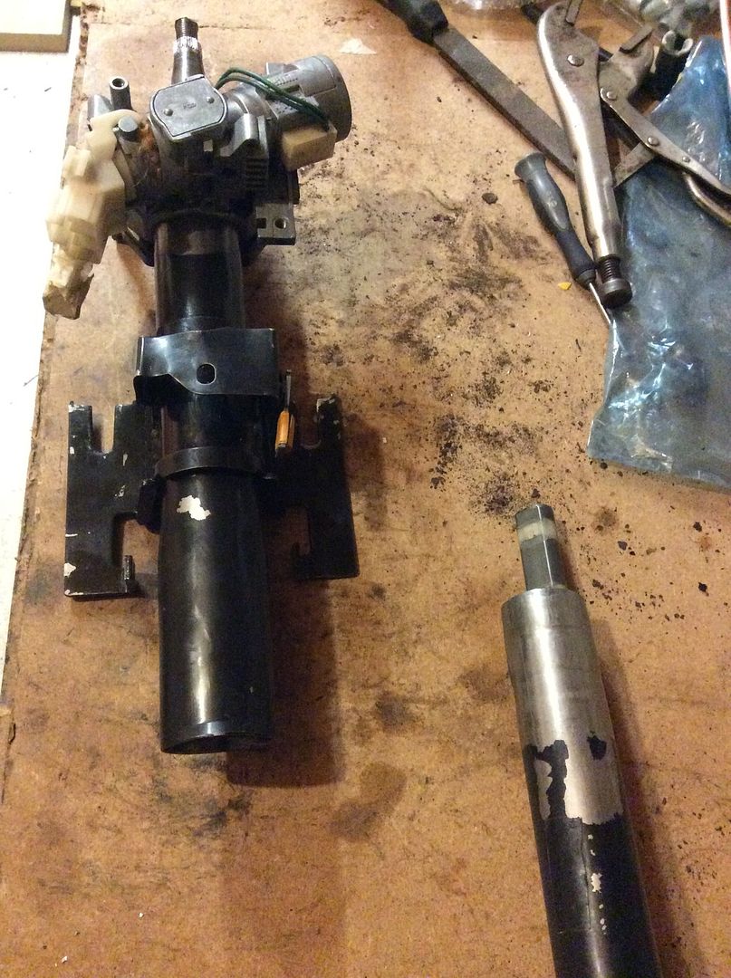 Before I waste any more time can somebody confirm that this has rendered the steering column useless and I need to get a replacement, or if it can be saved how to go about it? Ironically the last bit of length came from the lower shaft in the engine bay! |
|
|
|
Post by exoRy on Apr 23, 2016 12:53:15 GMT
sorry to go slightly back in time - did you have any problems with the servo fouling on the frame when fitting with the spacers??? |
|
|
|
Post by ian360 on Apr 25, 2016 18:03:41 GMT
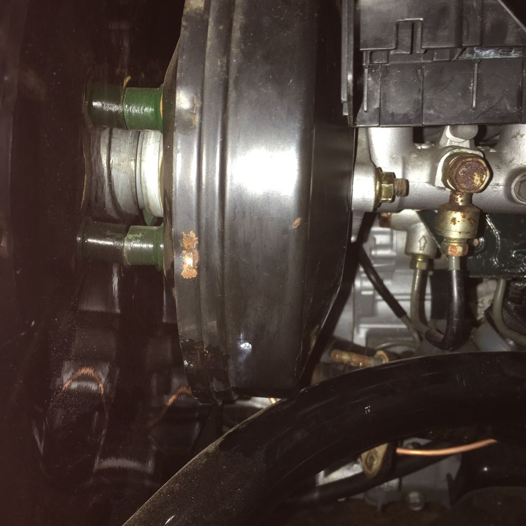 Exory - I hadn't noticed any problem fitting the servo, but on checking it is resting against the frame. Don't think enough to matter one way or the other, could probably grind a whisker off the spacers to pull it closer to the bulkhead? Nothing is being distorted it literally rests on that point rather than being wedged in. Hope that helps. |
|
|
|
Post by exoRy on Apr 26, 2016 18:31:26 GMT
thanks - yours looks fine and almost flush - doesn't seem anyway near as severe as mine.
|
|
|
|
Post by ian360 on May 9, 2016 11:31:28 GMT
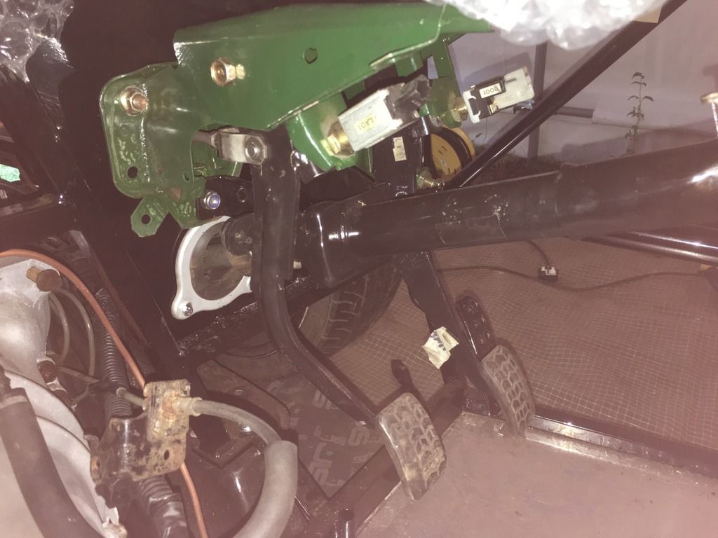
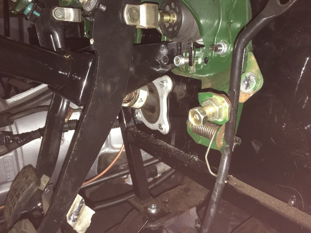
Just a quick update from the last few weeks. Decided the steering column was a goner so ordered a replacement - actually fitted so much better than my original so £20 well spent. Then had to remove for painting and to fit the rubber gaitor and rivnut. Also made new line from clutch master to slave. All done and all now put back together, hopefully that is the pedals now sorted. Few pictures - 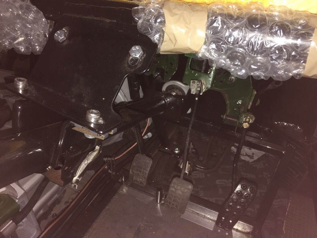
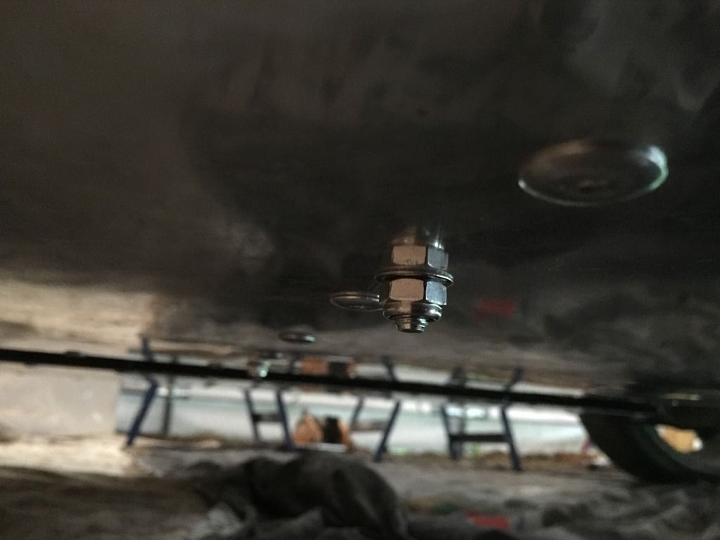
Then set about sorting the driver seat - hadn't been looking forward to this reading about all the problems with seats fitting etc. I had already marked holes for the runners before riveting the floor on, so was happy I had clearance. Wasn't so sure about the size of bolt / hole needed. I went with M8 as felt M12 would be getting very close the edges of the cross member from my markings. The bolt head is marked 8.8 which I think is acceptable strength? 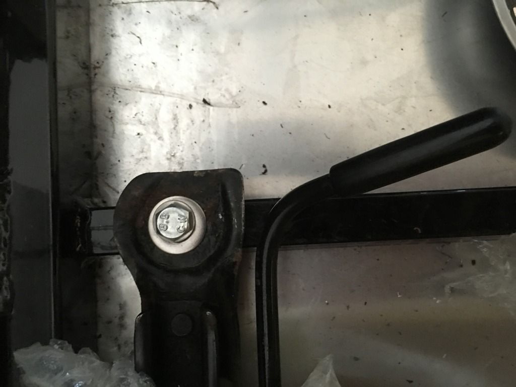 And using 40mm length with some washers this is what protrudes underneath - And using 40mm length with some washers this is what protrudes underneath -
For the MEV seats themselves, needed a bit of fettling to get height sorted both for rear clearance and for the actual runners / sliders. Addition of a number of washers 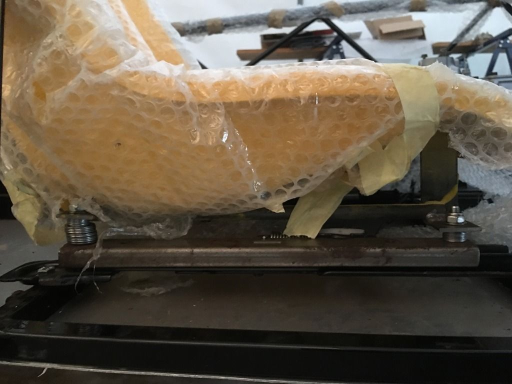
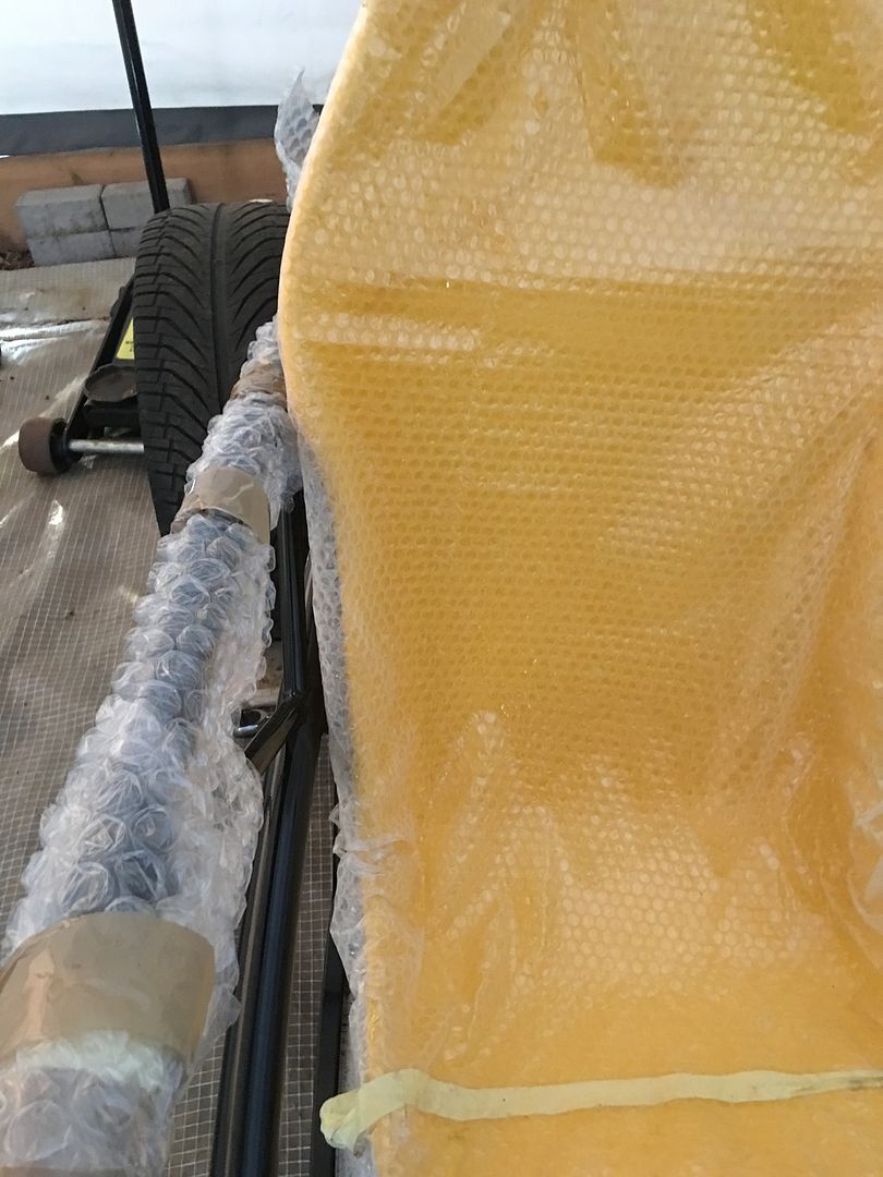
and have full operation forwards and backwards with full clearance of the chassis.
What I would ask you all is if this is the acceptable way to fit - are all those washers allowed as spacers or is there another method more applicable?
|
|
|
|
Post by ian360 on May 17, 2016 8:14:26 GMT
Started to work on the rear end fuel tank and cover. I think the new style chassis benefits from coming with mounting tabs for the tank, just need to drill holes as done here 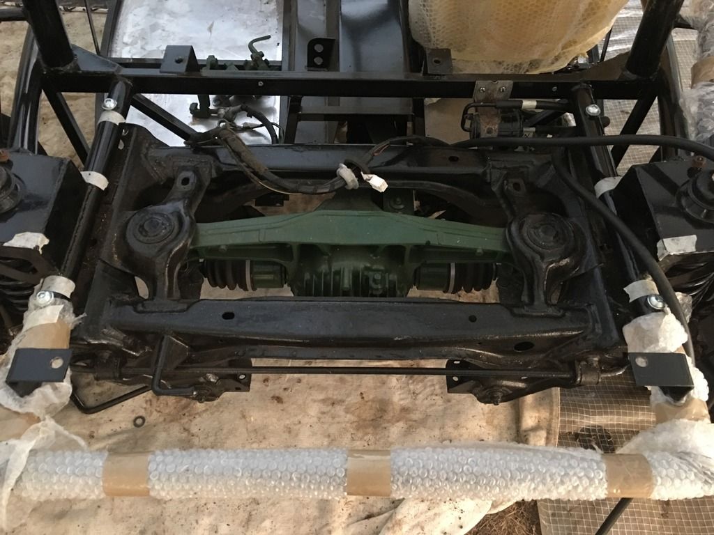
Decided to rotate the tank as per the build guide, mainly because mine offered up to all tabs better that way, and secondly as a personal preference I like filling up on the drivers side! Even so the holes do get quite close to the edge of the tabs, these are M12 size 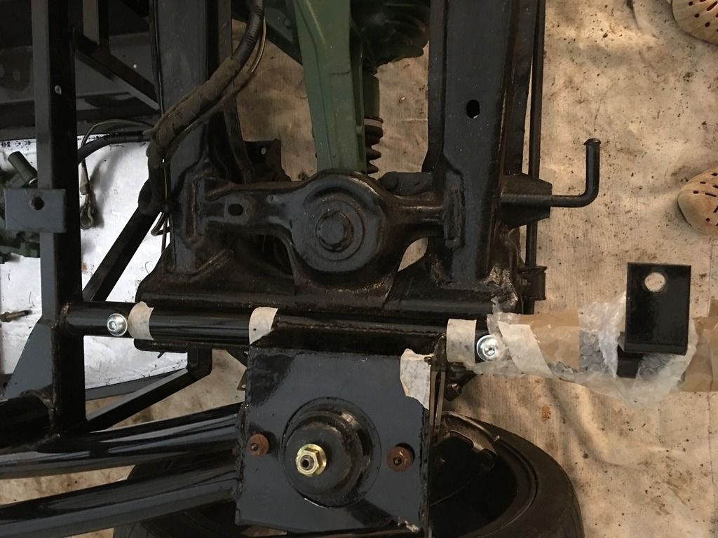
New holes also needed in the tank rear, just would not line up with the tabs in any configuration with the old ones. 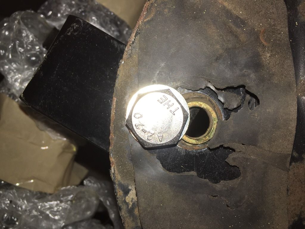
Washers both sides there was enough to get a good fix. 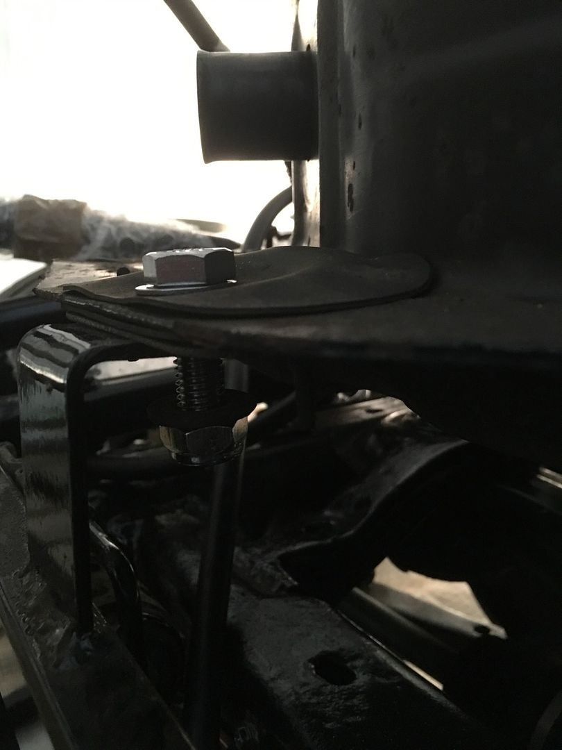
I then offered up the fuel filler pipe - obviously this is going to need more thought and adjustment! The angle isn't great on the picture but they protrude way past the rear bulkhead. 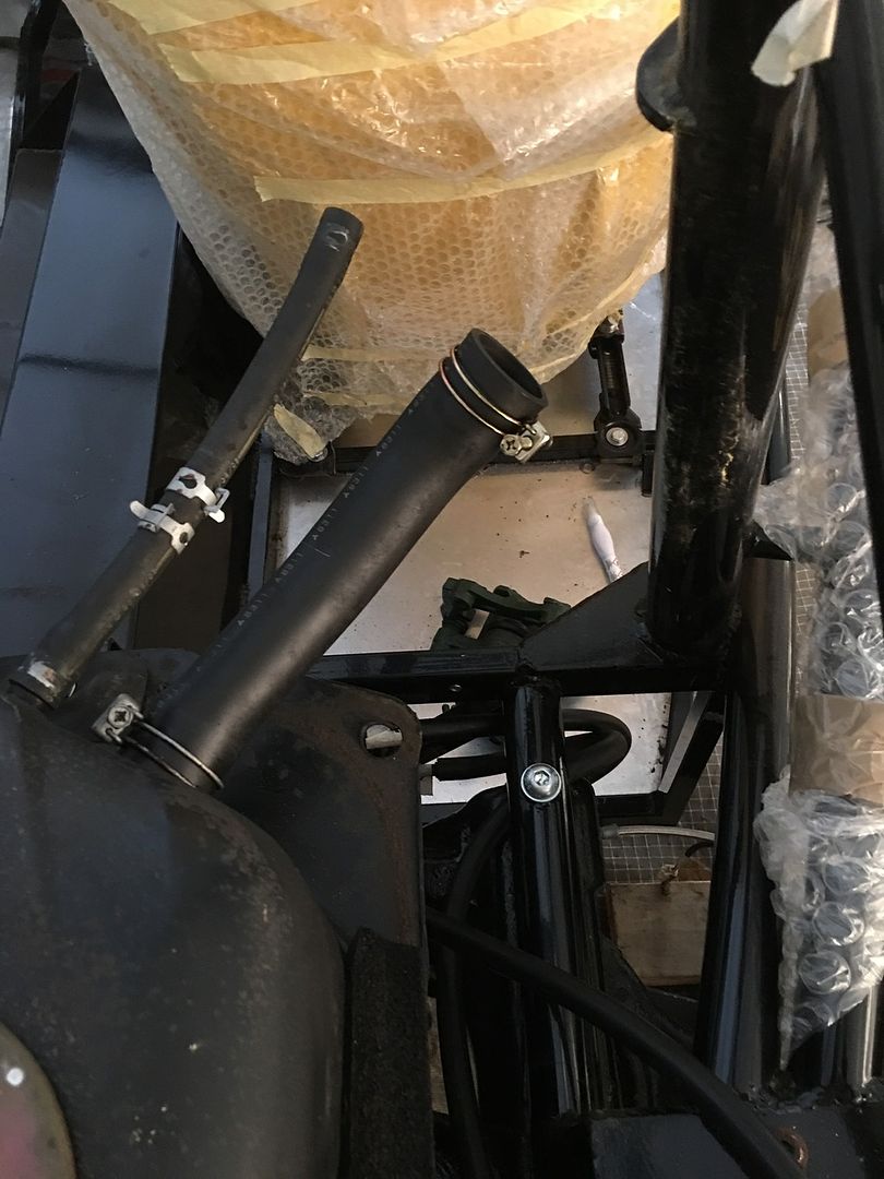
On to connecting the fuel lines. 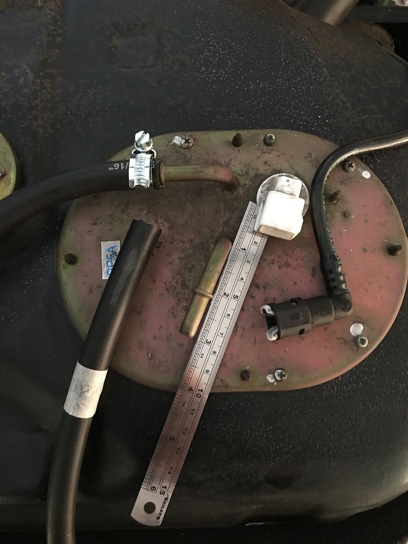
Question / advice please. Original (hard) fuel lines were connected with the clip type connected, seen right in the picture above. Having switched to new rubber fuel lines throughout, I have attached using jubilee clips, as above on the return line. The hard line on the unit has a flare about 2.5cms from the end, and the flexible pipe I have will not pass over this. So just asking is the jubilee clip route sufficient given the pressure in the system, or should I look to utilise the clip connectors again?
Finally, with some trepidation, set about cutting out the rear cover to clear the suspension. Actually not as bad as I was expecting, easy with a dremel and after making a template with a good margin of error, just kept working away a bit at a time and rechecking. 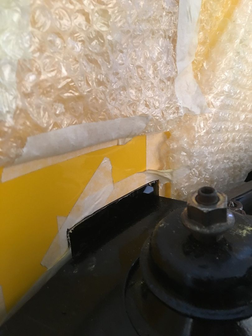
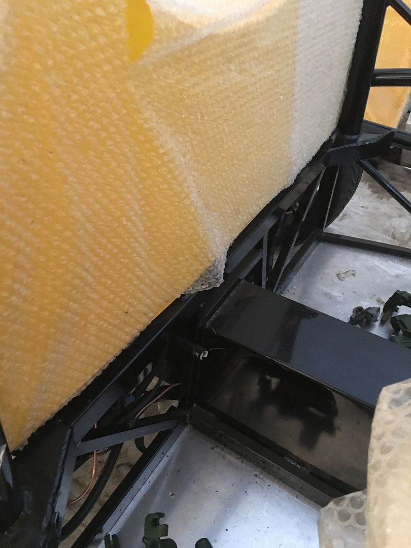 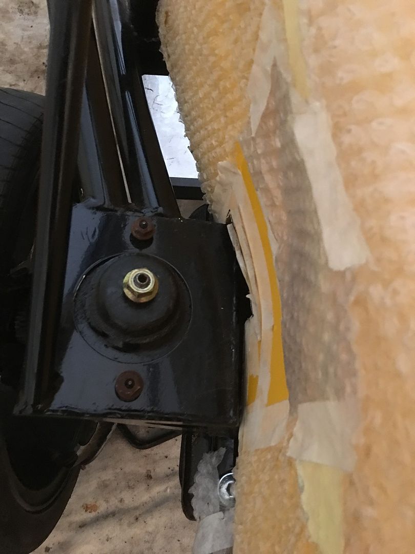 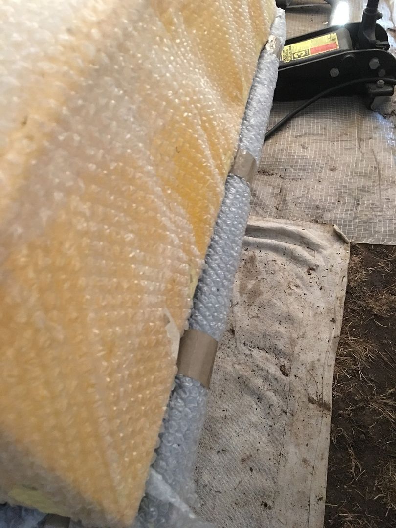
The gap over the suspension is marginally larger than I would have liked, but for a first attempt I am happy with the overall result, and a bit of edge trim will help!
|
|
|
|
Post by snowbird1 on May 17, 2016 15:17:26 GMT
Question / advice please.
Original (hard) fuel lines were connected with the clip type connected, seen right in the picture above. Having switched to new rubber fuel lines throughout, I have attached using jubilee clips, as above on the return line.Q
The hard line on the unit has a flare about 2.5cms from the end, and the flexible pipe I have will not pass over this.
So just asking is the jubilee clip route sufficient given the pressure in the system, or should I look to utilise the clip connectors again? The only way I know of making secure connections to on 'quick connect' type fittings is to use the original style connectors. I wouldn't rely on rubber hose with no barb to retain it. 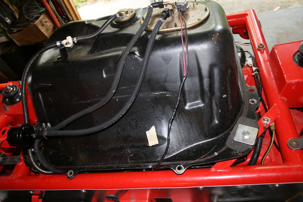
|
|
|
|
Post by mawdo81 on May 18, 2016 19:32:26 GMT
You can get connectors on eBay, or reuse the original if appropriate...
|
|
|
|
Post by snowbird1 on May 19, 2016 14:37:38 GMT
If you get aftermarket ones make sure they latch properly, the stubs on the pump are slightly different lengths.
|
|
|
|
Post by ian360 on Jun 1, 2016 8:23:56 GMT
Thanks for replies and fuel connectors on order, hopefully here to fit this weekend.
Have been fitting the radiator the last couple of weekends - it took so long as went off track with the new MEV bonnet hinge.
I've noted on that separate thread that it doesn't fit a MK2 radiator! Several emails to Stuart trying to figure out how it should be fitted resulted in finally noting this point, which we should have covered from the start. Just a point for anyone considering buying these brackets - great idea but you will need a rad from a MK1 to fit it.
So back to square one and made up my own brackets to fit
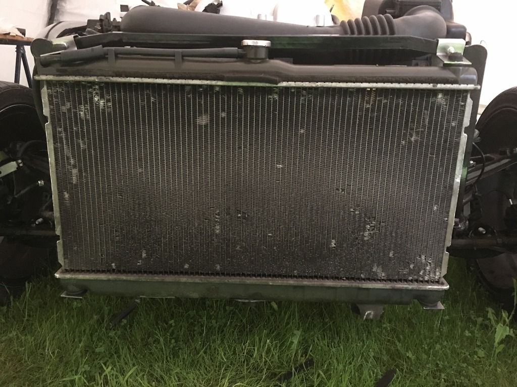
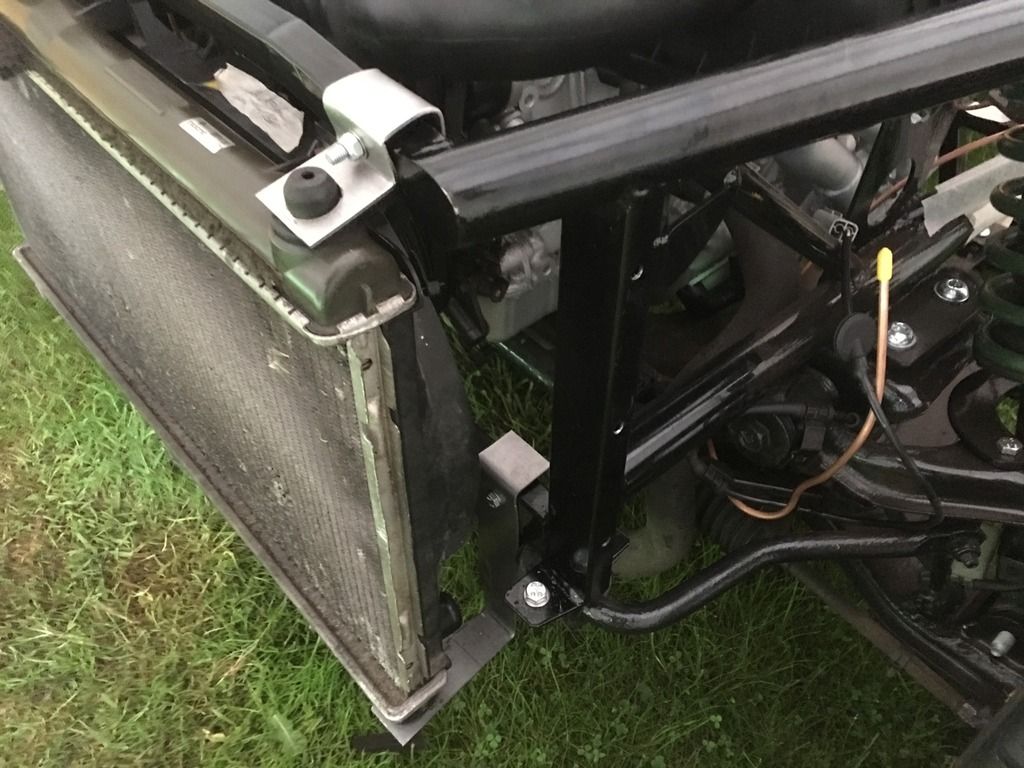
My bracket making is getting better but still rather crude, so I will more than likely remove them to tidy up once everything else done. Think it will be necessary given some of those sharp corners. The rad has to fit on the outside of the new chassis, and just clears the bonnet enough for that to still fit snug. As a point for anyone else on the new nose / chassis design double check this before fitting as it is tight and can leave quite a gap at the bulkhead frame if not careful!
There is nowhere in the engine bay for the original expansion tank to fit, so will need to source a new smaller one - does anyone have any simple solutions to this?
Thanks |
|
|
|
Post by miket on Jun 1, 2016 13:21:23 GMT
I nicked an idea from earlier in this forum - cycle drinks bottle. I went for one marked as dishwasher safe (for temperature resistance) and many come with their own mounting rack. Rad pipe in thru drinking orifice and drill hole in cap for overflow with elbow if nec.
From memory I think someone on here sourced a preloved tank from ebay - from a Hyundai Getz if I remember rightly.
|
|


 Trial fitted with the brake disc and caliper


 I have the rear line still to do which will have to be in situ, didn't feel ready for that yet! Also need to p-clip all the lines to the frame, but will do that once I split the two again when access will be easier.


 And using 40mm length with some washers this is what protrudes underneath -


