|
|
Post by gwnwar on Jun 1, 2016 15:43:01 GMT
Just a note on your radiator the top tank is turning green which means it has seen better day and will need replacing soon.
If in the budget get a NA radiator and use the new bracket kit. Radiators are cheap.. How are you planning to get the lower hose on looks like the bracket is blocking the hose connection..
|
|
|
|
Post by dave on Jun 1, 2016 21:45:51 GMT
|
|
|
|
Post by ian360 on Jul 7, 2016 8:06:00 GMT
Have been working through the wiring loom, interrupted by holidays, but have managed to get most of it connected. I'm pretty sure I have all the earth points located and fixed, the lights I am starting on working out how to connect, and think most connectors have found the right home. I decided not to cut anything out of the loom at this point, but reasonably pleased my markings remained and am able to discount a lot of the connectors.
However, there was always going to be some issues!
For starters, can anyone advise what this connector is for: 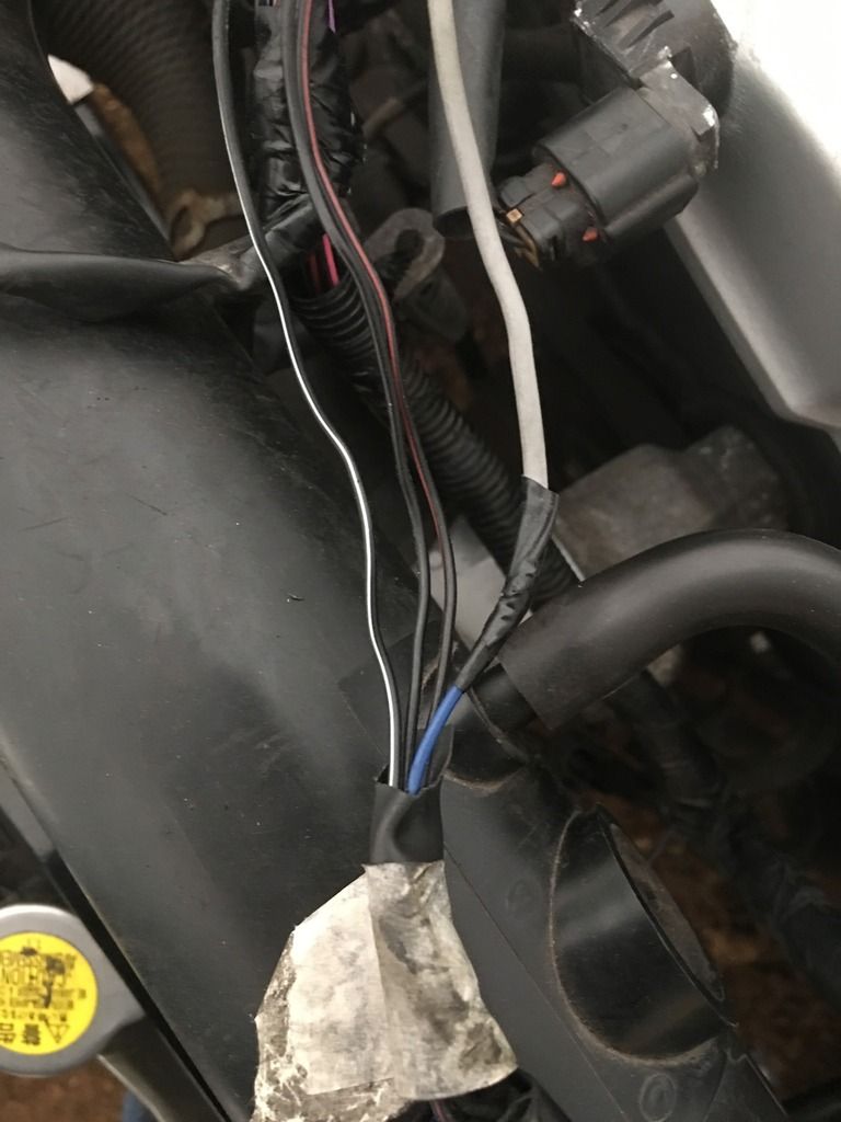
I stripped the insulation back and four wires are Grey (that is main in the loom although looks like it's been chopped into at some point) / Black White / Black / Black Brown
It's position on the loom put it towards the front of the engine, I marked it with numbers as not sure what it was connected to on dismantling but can't see any spare connectors in this area? I've checked wiring diagrams and only ones with grey wire are horn relay or heated rear window? Any guidance please Thanks
|
|
|
|
Post by gwnwar on Jul 8, 2016 2:33:38 GMT
Post pic of connector. is it yellow inside..
|
|
|
|
Post by ian360 on Jul 8, 2016 6:05:19 GMT
Problem solved - it was oxygen sensor in exhaust, I had removed it when I painted the exhaust and put it safely away. Remembered as I was searching for connectors and it was all marked up with corresponding number.
|
|
|
|
Post by ian360 on Jul 21, 2016 11:37:11 GMT
So have been spending hours connecting, disconnecting, routing and re-routing the wiring loom. I took the decision not to cut anything out until I was sure everything was working. The only exception being the electric aerial wires which I am pretty sure I don't need! The only problem this causes is a mass of wires that ultimately won't be needed getting in the way. I now have everything I think I need connected, and life on the instrument cluster. The brake and ABS lights aren't going out but that's to be expected as not connected yet. Despite the tedium it is quite therapeutic, and starting to look a bit tidier. 
For a change of scenery decided to finish the rear stays and fit the new discs and pads I have had for while, along with the calipers I cleaned up many moons ago. 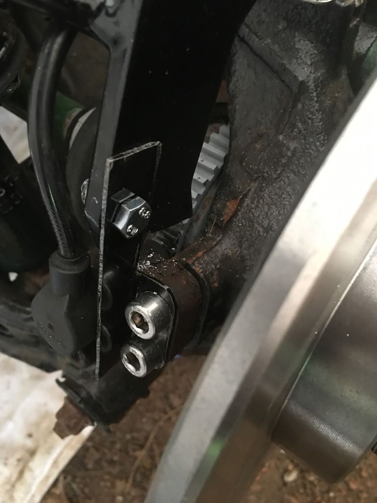
As noted earlier, with the ABS remaining the rears stays need holding securely with an additional bracket. I also finally figured the reason the ABS line wouldn't secure anywhere was because I had them upside down on wrong sides! Switched them around and mounted along with rear brake pipes. 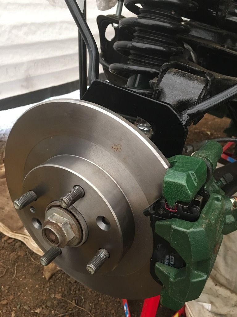
Just waiting on spacers now to fit new wheels!
Next job to tackle is the handbrake. Have done some research but need some advice please. The cables I have seem to reach the brake caliper fittings easily with the handbrake in roughly the position it needs to be. I haven't needed to pass it through the centre tunnel for the drivers side - it passes around the back and over the PPF. Hope this picture shows what I mean 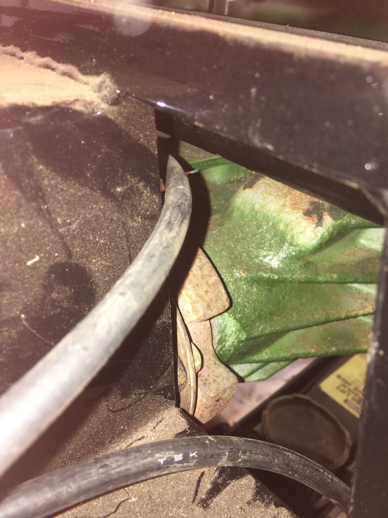
The cables fit into the holes comfortably at the front 
My questions -
Is there any reason to feed the driver cable through the centre tunnel?
Do I need to attach this spring to the bracket ? 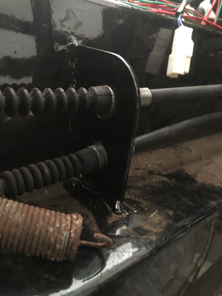
I feel there is quite a margin for error within the handbrake adjuster with regard to where it sits - am I over simplifying things and do I need to be a bit more 'engineer'?
Just want to double check before I start drilling holes......
|
|
|
|
Post by miket on Jul 21, 2016 14:43:50 GMT
My two-penneth;
1. no there's no need to break in to the tunnel - my rhs one just makes it round the back albeit tightly.
2. I don't believe there's a requirement to use the spring, but I did - using one of those dome-nut/bolt-with-a-hole-thru - the sort that secure pushbike mudguards on the end of their stays. Looked tidy.
3. I think gwmwar has noted the right approach to handbrake positioning in another build (or two) not too long ago - from memory it's:- adjust rear brake calipers to just touch, slacken off handbrake-adjuster right off, then position handbrake ... but please check further before drilling!
|
|
|
|
Post by ian360 on Aug 16, 2016 8:51:11 GMT
Small amount of progress the last few weeks as other distractions have taken precident.
Progress- handbrake fitted and working, but haven't located the wire for the switch. I think it was removed as I undid the insulation as only hanging on by a wire, so need to check diagrams and get that refitted somewhere.
Thats the only issue I think with the wiring now, everything else seems to be working.
Front end and middle section of exhaust fitted.
Had some leakage issues on the brake system which came down to loose connections (wasn't sure how tight they needed to be) and a dodgy flare which ended up meaning getting a new pipe done for the front. No big issue and system now leak free.
When I get around to bleeding the system, does the abs unit need powering up to allow the pumping of the fluid?
As I was adding liquids decided to fill the whole system and make sure the mechanics worked. Engine, gearbox and diff oils all added and no leaks. Coolant less so until I realised I had put the thermostat and gasket in backwards causing the leak, swapped them round and all sorted..
So now have what seems to be a leak free system, and electrics all connected. I'm about ready to turn the key for the first time!
Any advice if anything else needs doing before I do this please? Haven't filled the clutch reservoir yet or fitted the gear lever - will this cause an issue?
|
|
|
|
Post by gwnwar on Aug 16, 2016 13:54:11 GMT
Make sure gear box is not in gear. You say no shift lever installed..Did you fill the shift turret too with gear oil..
|
|
|
|
Post by ian360 on Aug 18, 2016 9:58:55 GMT
Thanks gwnwar - subsequently filled the turret and installed shifter, no gears selected.
Double checked everything again and with a sharp intake of breath and turned key. This happened - if video has uploaded correctly
Not really!!
This was after about 20 minutes of head scratching as the engine was cranking but not firing. Checked again all connections and earths, all seemed OK, fuel pump was working, only thing was fuel gauge wasn't moving.
Eventually pinned it down to insufficient fuel - all of 4 litres I had put in the tank was 'sitting' at the front and nowhere near submersing the pump / sensor. To avoid filling the tank further I unbolted it and tipped it backwards, fuel covers the working parts and hey presto we have life!
Having never inspected a fuel tank in situ some questions or reassurances sought -
Would 4 / 5 litres of fuel in a tank be considered too little to register on the gauge and actually be below an amount that always sits in the tank?
does the Mazda tank, when turned 180 degrees and fixed to the chassis brackets, need the spacers for the purpose of tilting it backwards to maximise fuel use?
I needed to tip it around 45 degrees to get the fuel in the right place so can't think spacers add this much beneficial effect.
This is more learning above anything else as don't intend to run the tank dry in normal use.
Really chuffed fed to have working running engine that seemed to be ticking over happily. Only thing is ABS light doesn't go out so need to investigate that reason. Not tempting too much fate didn't run it that long to see if fans kick in, but oil pressure looked good and no leaks appearing.
Plan in now to start snipping away at the loom to tidy that up a bit.......
|
|
|
|
Post by ian360 on Nov 15, 2016 20:03:50 GMT
That last sentence was a merchant of doom! It's been hours spent tidying up redundant circuits, wrapping and unwrapping and fitting the somewhat lighter weight loom back in place. Have really enjoyed working through the wiring diagrams and following them back into real life - and to keep everything working. Have run this in with a few other jobs, such as fitting a new radiator onto the MEV brackets and have the headlights and indicators installed. Now working on the rear lights and have a quick question which might be obvious but want to be sure -
I have reverse lights on both sides from the donor. Only one comes with the MEV lighting kit. Both originals still work after my loom snipping exercise, but one needs to go. Do i just cut off the bulb holder and terminate the wires, and will this keep the other light working ok? Difficult to see from the diagram if one affects the other directly?
|
|
|
|
Post by ian360 on Jan 12, 2017 12:45:18 GMT
I really have got behind with updating my thread, so here goes! Not that this will offer too much in way of advice but good to keep the thread current. Certainly the electrics have been one of the stalling factors in taking time to sort out. Also I moved from working in this
to having this built 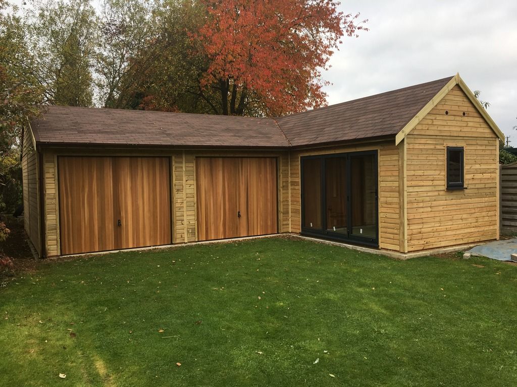
single garage and double workshop so at least I now have some space, warmth and a decent floor on which to find everything I keep dropping! Fitting it out took most of the end of last year, but in between I did manage some progress.
The wiring loom was completely unwrapped to remove redundant circuits 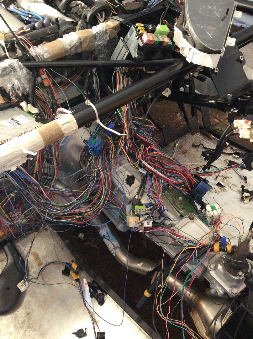
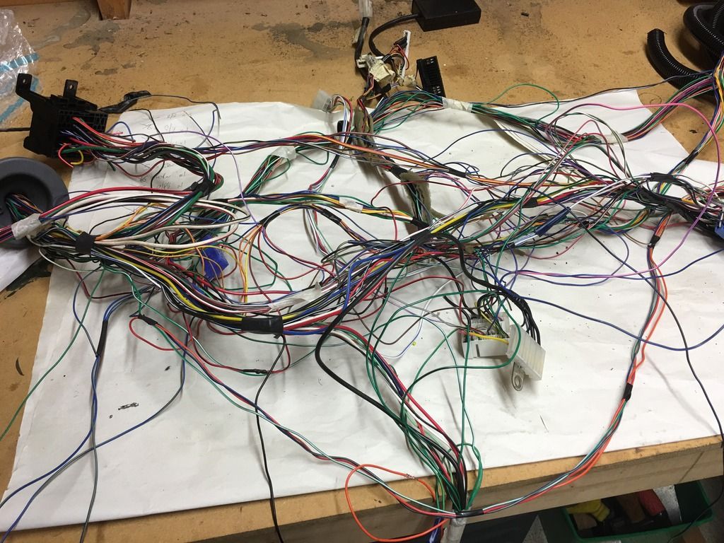
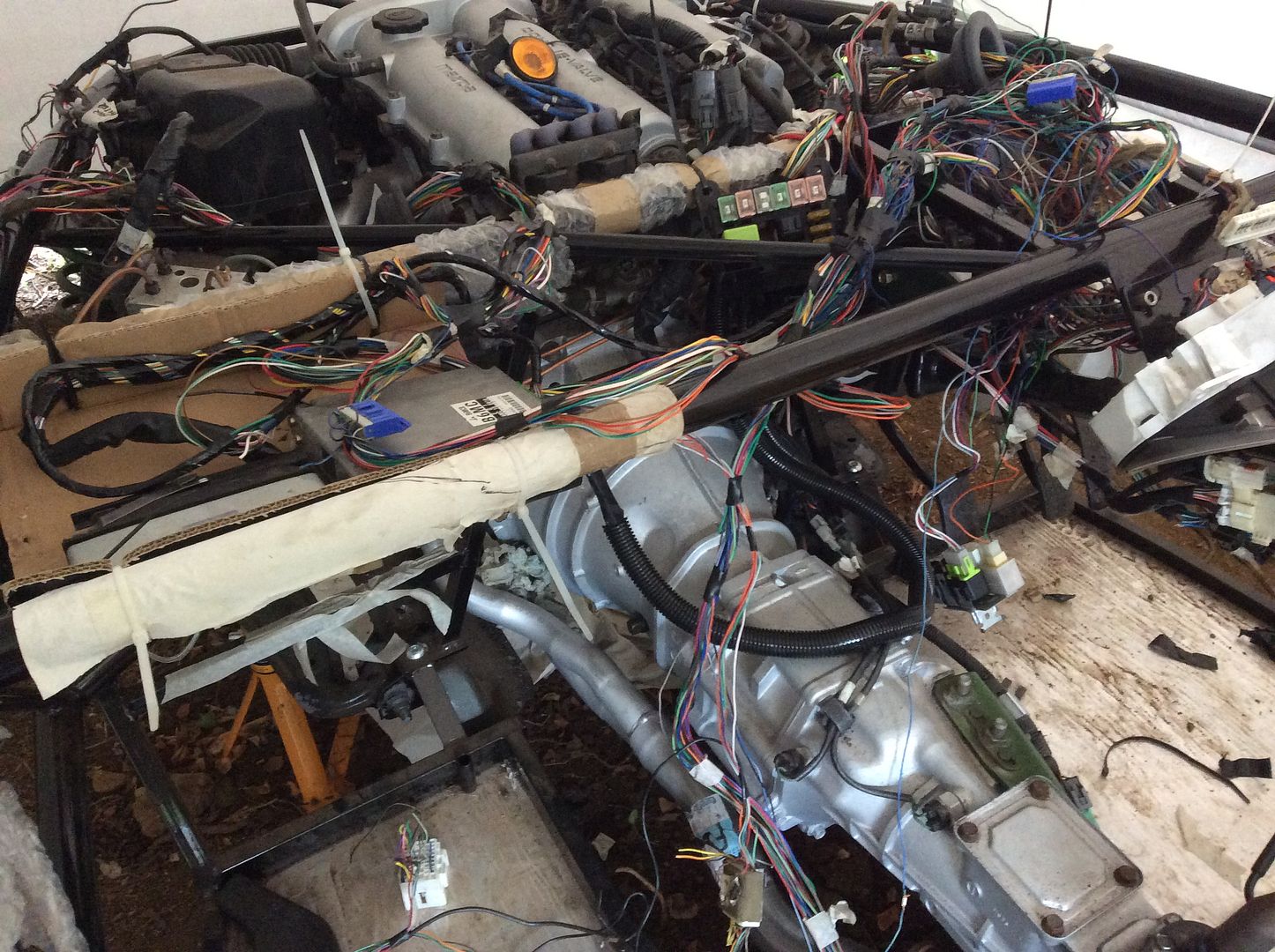

Basically created a massive tangled pile of wires and took a lot of patience rewrapping and placing back into position. Maybe I did something wrong at the outset to complicate the process, but for what was removed I really question if it is worth doing? Although now I have much more knowledge on car wiring diagrams! 
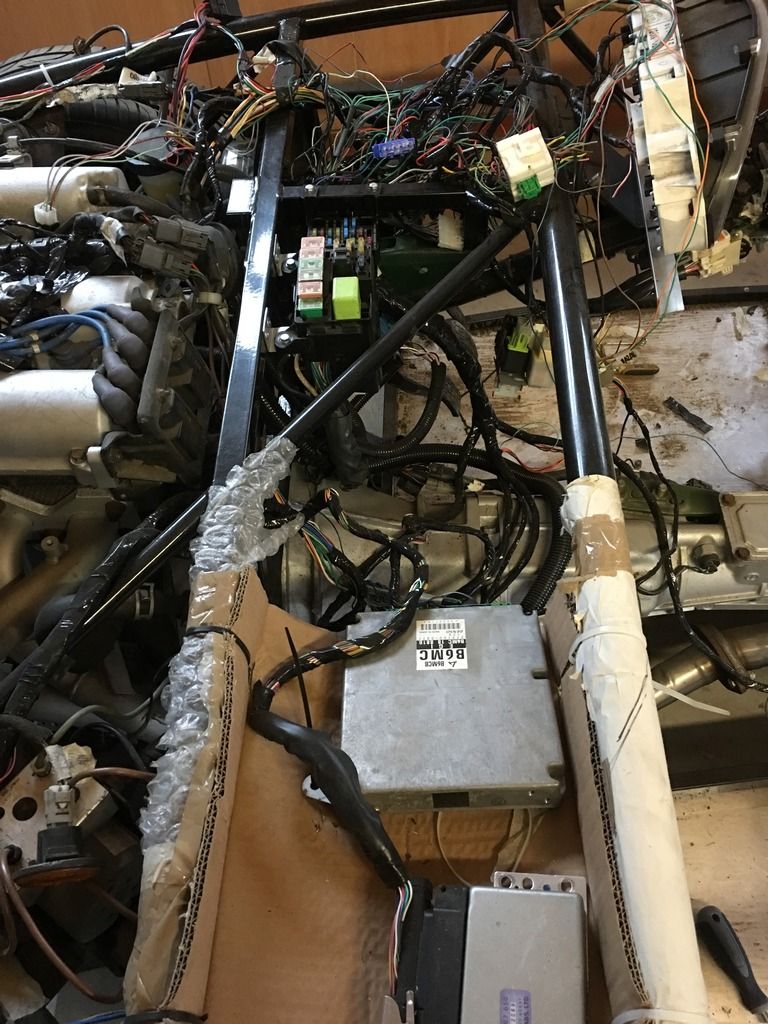
Fixed the two fuse boxes into what appeared the most sensible place, and eventually got all the above more or less where I needed it. Temporary electric tray took a bit of a battering as well. Then moved to the back and started on the rear lights. I am using the MEV supplied light kit and first thing was to make new connections and make sure everything worked. Apart from one faulty bulb (didn't expect that out of the box - note for anyone else check this first as saves a lot of time trying to figure out why your wiring isn't working!) but apart from that all present and correct 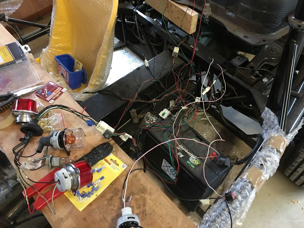
Front headlights are quite simple to connect, need the indicator drilling through the main body, and on the new chassis easy to fix into place. Haven't done a final adjustment for position yet 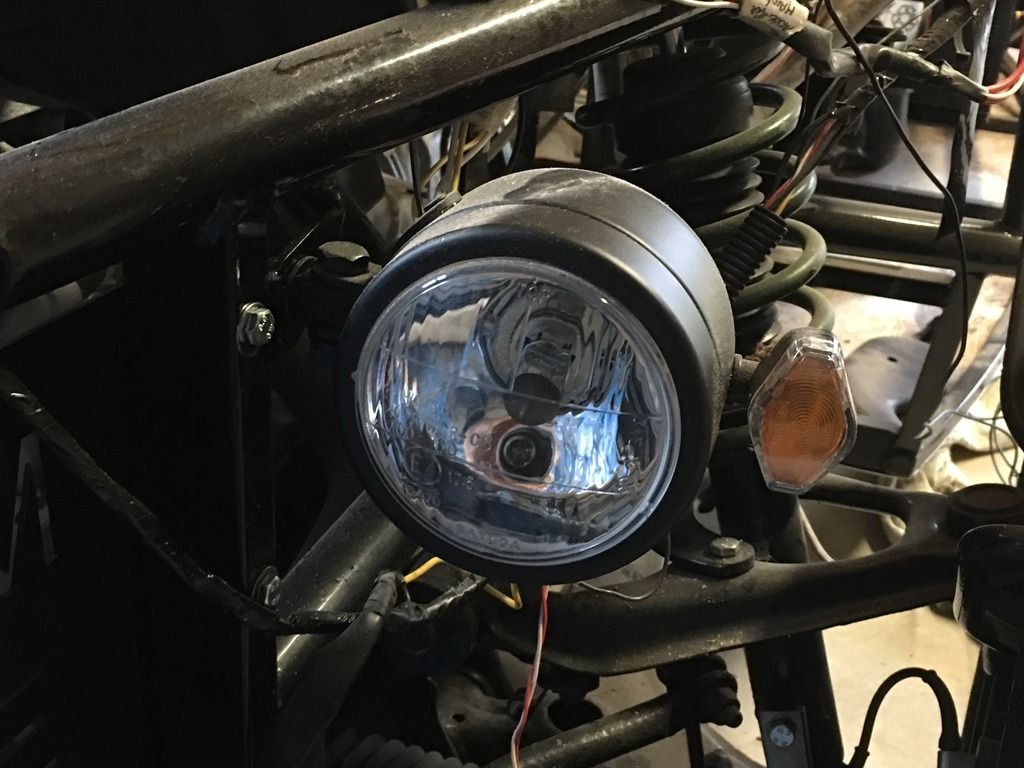
Both in place along with newly purchased radiator and fitted on the MEV bracket. 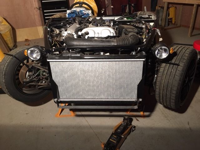
Horns are connected and fitted to the frame behind the radiator.
Last thing for moment on the loom, the main fuse box to battery runs along the PPF, and can be fixed using original mounts. The rear section of the loom from the lights needs to run along same section, and there is a large connection box to fit. I cable tied to two looms together but it is very tight in the tunnel, if only for hands to work in, and needed to remove all the earlier fixed fuel and brake lines to get in there. Something to think about for anyone not at this stage - I'm not sure if electrics comes before mating the chassis and PPF generally but it's worth considering how to do it in advance.
For the loom coming out the front end on the gearbox same thing cable tied to loom mounted from original. Should give a good enough fixing for IVA purposes? 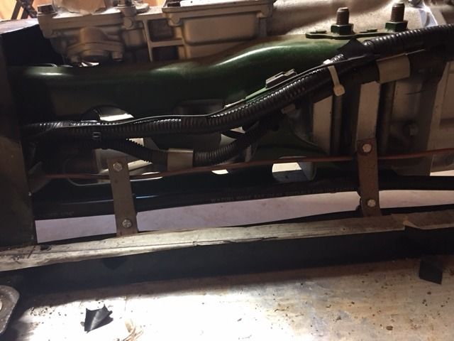
For a change of scenery decided to deal with the body panels, tunnel and bulkheads. Lots of templates and measuring involved, and good tip to make a fixing point that you can keep going back to as reference. 
Centre tunnel needed a bit of cutting around the exhaust downpipe but otherwise was persuaded into place reasonably easily, being fixed with rivnuts. Passenger bulkhead supplied panel is nothing like the correct size or shape and needed a lot more work to fit. I decided not to overcomplicate fixing and will tidy up any gaps with edge trim as they aren't that big. 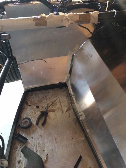
I have bashed the aluminium though with the drilling and cutting so decided to carbon wrap it - good excuse to try something else new as well! Fitted the electric tray 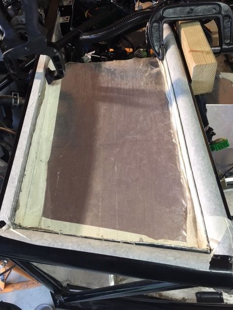
and laid out loom ready for fixing. 
Engine bay loom all in place with p-clips, just need to connect the headlights. 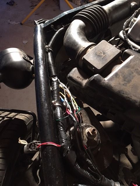
Also fitted the fuel tank and rear cover, next job is to place and fit the rear light clusters.
That gets me up to date, pleased with progress and now planning on aiming to be finished by spring for IVA and ready for summer. I think there is light at the end of the tunnel to realise this, sitting down to list final jobs which although is still quite long I think the worst of the problem jobs are now done.
Welcome any comments on anything from the above that isn't correct and again thanks to this resource in helping make this possible.
|
|
|
|
Post by iparnell on Jan 12, 2017 16:08:43 GMT
Have you thought about drain holes in the electrics tray..not sure if your planning on putting cover over it under bonnet but either way it might be worth considering if you do get caught out in the rain at any point. Cheers Iain
|
|
|
|
Post by mikeeyboy on Jan 12, 2017 16:33:49 GMT
Good build thread this. I am just ready to get my frame painted and then start on the rebuild, I must admit, I am dreading the electrics a little bit and you haven't made me any less worried! ha.
Out of interest where did you get the wooden workshop/garage unit from? I currently have a double garage but we are looking to move at some point and that looks like a great option if there isn't a garage with the new property. If you do not mind me asking what is the rough cost on something like that?
Thanks
|
|
|
|
Post by ian360 on Jan 13, 2017 9:21:05 GMT
Iain - good point to consider, although there seems to be so many places for rain water to get into might be a losing battle. I guess a couple of holes wont do any harm. Is there anything else that can be done to give some protection to ECU - it does look a bit exposed to the elements even being under the bonnet? Mikey - It's an exercise worth going through, just be ready to devote some time to it! check out this website www.warwickbuildings.co.uk They did a bespoke build for us as had specific requirement, so cost probably more than usual. |
|