|
|
Post by roger32849 on Feb 3, 2014 22:35:35 GMT
Erik
I have an older Suzuki Burgman 400 in my garage. It is not a donor, but a good rider. When you asked about the bracket for the speedometer sensor I checked the Burgman front end. The speedometer Hall effect sensor has no retaining clip. What is has is a pair if raised casting stops on the inside if the front fork. These are more for proper alignment than a stop. You do not need anything to keep this sensor from rotating. When you torque your front axle bolt(s) the compression of the axle supports will hold the sensor tight. If it rotates, you have a serious issue, and a stop will not prevent it from turning. It is made of plastic and will shear right off.
Hope this helps
Roger
|
|
|
|
Post by edvb on Feb 4, 2014 2:11:00 GMT
Yes, getting everything to work and fit correctly takes quite a bit of time. All the bits of a puzzle have to be solved but after that it will be gravy and quite a bit of fun. My throttle cable will be here Wed. so then it will be time to button up the tunnel for good. Now this is fun work!
You will have a few more surprises as you continue your build but since you are this far it will be of no concern.
Keep on trucking.
Edward
|
|
|
|
Post by Scott on Feb 4, 2014 14:24:57 GMT
Erik, We have fitted a stop plate to our speedo unit, a simple angle bracket on the upright which tucks in the slot on the speedo unit, tightened down on the spindle better to be safe as if it does spin it will rip the wiring out of the unit and they are not cheap to replace,,  |
|
|
|
Post by erik on Feb 4, 2014 16:49:18 GMT
Hi Scott, Yes,that's the pic in the manual. I didn't notice the bracket at first  I think a tab on the inside of the forl may work as desired too. Need to have a closer look later, I had to outsource the fork assy for adjusting the caliper bracket. No big deal and if they do it neat I may reconsider to outsource the final welding to them too which is for me, a high risk because near everything oursourced on the tR1ke was done in lower qty as expected. @ Edward, for the throttle cable I used Shimano brake line outer cable and steel braided, nylon covered 0.75mm (75kg) fishing line. Inner resistance is minimal and no potential rust possible. I think you are referring to loom modding suprises right? The fork will be back next week. I want to send it for Schooping and powder coating. Then I can measure the exact bushing sizes and have them made. br, erik |
|
|
|
Post by erik on Feb 5, 2014 20:29:58 GMT
|
|
|
|
Post by edvb on Feb 5, 2014 22:24:15 GMT
What is Schooping?
No the surprise's are when everything is assembled and you forgot a calculation and go oh S!
I have a few of those along the way.
We all have different ideas on what the finished trike looks like and how we use them.
The good thing is that yourself, Scott and Roger are posting solutions to some problems we find.
Pictures are a thousand words so that helps quite a bit.
I am working on the throttle cable that I got today. It is one piece housing that incorporates ideas from you, Scott and Roger. Thanks for all your suggestions to get to this final design.
Since I have to look over my carbon windshield you know where I stand on that. Even with my Beemer I always was looking over the windshield for the purity of view in front.
On the wheel bushings you are correct in waiting till all the parts are powder coated. Use a micrometer to get the right size and get them made.
The caliper alignment was off but some washers on top or bottom of the caliper bolts corrected the problem.
Metal twists when welded even in jigs so mine was not bad and within tolerance of what I would expect.
I appreciate Scott's comments on the shocks and getting that part right. With Roger's input this is critical to get right and if you want the proper height to clear the speed bumps will require some finesse.
Scott if you are reading this any more detail even minor and what you felt on the track and driving brothers with your weight really will help all of us fine tune what we will need for our Eco Exo R.
|
|
|
|
Post by erik on Feb 6, 2014 20:08:33 GMT
Schooping is thermal spray painting of zink particles: nl.wikipedia.org/wiki/Thermisch_spuitenIt's ideal for extra corrosion prevention and I'm able to dremel the PU bushing holes into tolerance before turning the PU bushes down to light press in diameter. The inner diameter will be perfekt round to pivot. It's remarkeable everybody claimsit's BS to schoop the chasis but it'll raise the value of the vehicle bigtime if it's build to last forever. No powder coater who can talk me out of it It's not likely I do forget some minor details. For this reason I will build the loom before coating which gives me plenty of time to over tink the build I intended to use washers for the caliper alignment but this wasn't possible. I'll have it reworked by a professional because it will give me a PITA for sure if I do this myself. I'm looking forward to Roger's shocks. I'm no feather weight either. |
|
|
|
Post by edvb on Feb 8, 2014 4:25:02 GMT
Here in the US I coated the inside of the frame with a preservative made for this job. On the outside because all the welded joints were shaped and molded I could not use powder coating. But a great epoxy primer and 2k urethane worked well for me. I accidently created a 1/4" chip in the paint that I was able to touch up and polish out where it could not be seen. So for me I am glad I went this route. If I did the loom again it would be a masterpiece of simplicity but I am still happy how mine turned out. Erik even when you get done creativity never stops and you will see a better way after it is completed. The main thing it was the best idea that was thought of at that time. Because of the larger Rose joints I used my trike ended up with 2" more width on the front track. So I cleaned up the threads on the tie rods and came up with this. Chromoly 3/4" O.D threaded casing with a 10.9 M12 x 40mm x 1.50 threaded stud. Overkill maybe but I am getting that safety grin on my face that won't go away!  IMG_1932 IMG_1932 by evanbelkom, on Flickr |
|
|
|
Post by erik on Feb 8, 2014 8:49:57 GMT
Hi Edward, The rod end extender looks pretty neat. Very similar of the one included in the kit. It's always good to make safety parts beefier as expexted load. However, On the An400 rear shock bolts I noticed these bolts are low tensile which made me use 8.8 for the front assembly because they are zink plated unlike high tensile bolts. On industrial vehicles painted vs powder coated is about 50/50. some claim powder coating is too hard/brittle but having to paint many parts is more expensive as powder coating. To prevent rust underneath any coating I do prefer the zink layer in between. It's an additional protective layer in between the chasis and bottom plate as well where the coat (wether painted or powder) may wear under friction. It's just a personal preference but i guess both methods work fine. In the chasis I use anti rust (tectyl) spray cans before assy. There is always a better way to build a kitcar. For the exo I like this one to be e-powered pretty much but problem is it should be used for daily comutter to beat costs and a fully closed version like Elio would be mandatory. On the tR1ke I'd suggest to make structural changes on order or even convert an Atomic to trike. It's never good enough if one gets into detail but one needs to know when to stop modding or else it's a waste of money. for simplicity sake I cancelled the cigaret lighter socket and connect the nav pod wire direct to the loom. I do like little storage space (chain+lock) tough and am keen on these cans but need to browse around a bit. www.twistedthrottle.com/twisted-throttle-tool-tube-w-mounting-kitLeft fork is backhome. Cost me 100 euro to correct the caliper bracket. More as expected but the beads are great. I might outsource the harness braket welding to them too and do the coupling nuts myself (siide weld only because I have them Schooped around for rust protection later). Hope to mount the front fenders today and i gues they are ready for coating. Too bad it isnn't wise to do many things at the same time. It'll get pretty hard to keep a clear overview on the project. This will slow the building pace for this moment but that's alright. I am a little concerned about the weather getting better early which forces me to clean the garage for the tR1ke testing. For the loom I haven't decided to bypass the wiring or open up the loom and clean her up. I do like to keep the original locations on the an400 but this might be a puzzle later. |
|
|
|
Post by erik on Feb 10, 2014 20:37:50 GMT
Parts are ready for coating. The bushes are a perfect fit but need to be reworked when the forks are coated. The boots fit perfect! 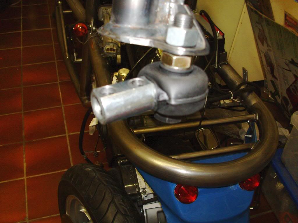  |
|
|
|
Post by erik on Feb 11, 2014 20:00:38 GMT
Tacho sensor is secured Most hardware went to the coater exept chasis. The bushes turned out to be great and it's very likely I need only to get me a tacho sensor replacement bush. How did you improvise on this. Justa straight forward metal bush as like in the sensor cap or a more sophisticated one for FOD pretection to the bearing? Cuttiing the loom brackets to bits and prep for loom build. Not sure where to start and I'll take some time to familiarize with it. br, Erik 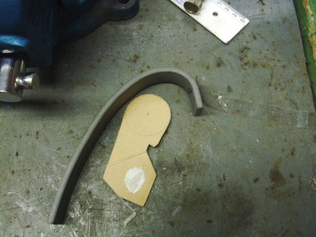 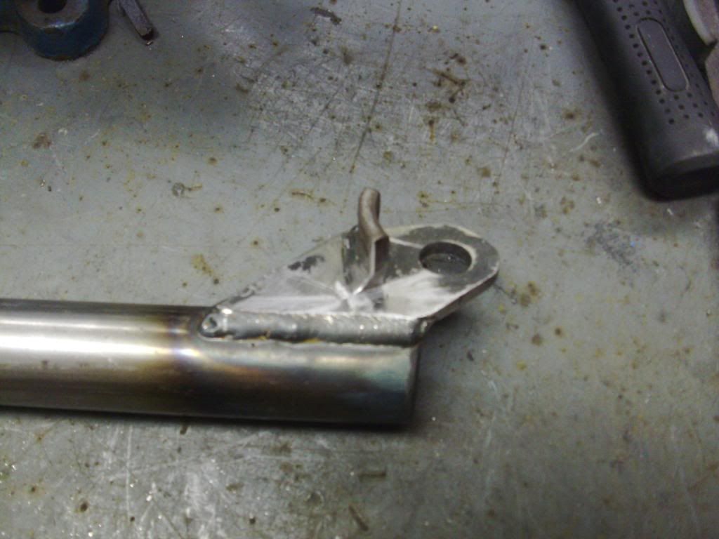 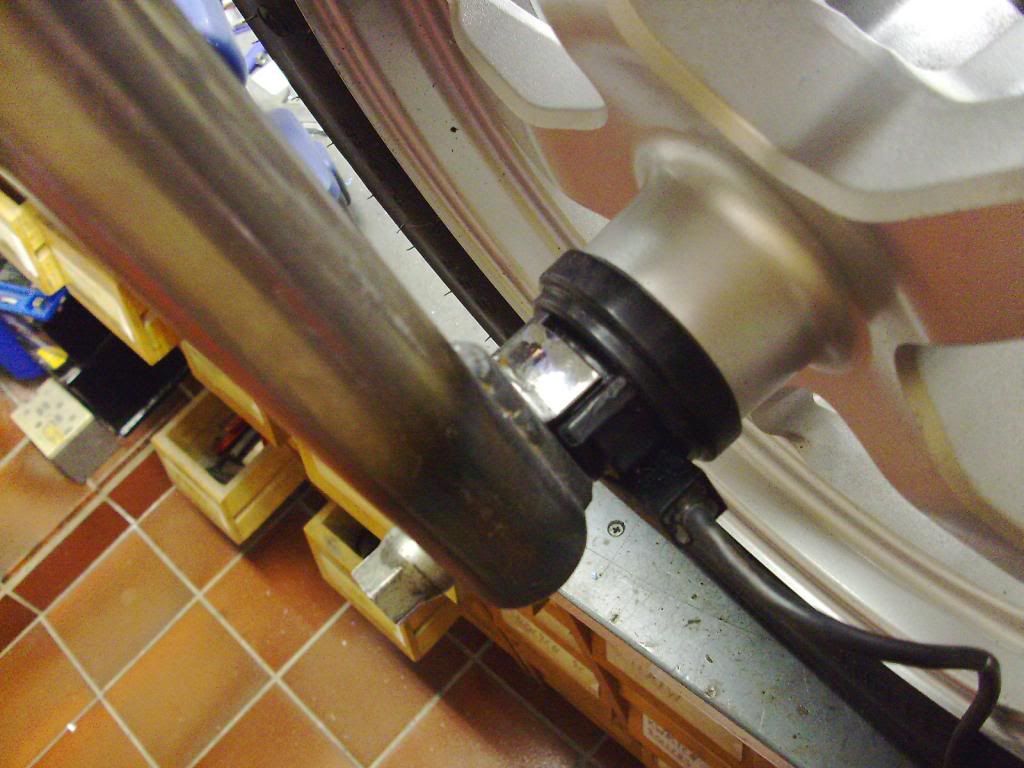 |
|
|
|
Post by erik on Feb 11, 2014 22:17:16 GMT
question: The small white connector tied to the saddle switch doesn't have any purpose right? Just a detail I cannot recall from footage or memory. Not sure if i can discard unused connectors. They may be used as readout connectors for service? i may as well tie them to the loom just in case. I opened the loom and see what I'm heading for OMG... thx in advance, Erik 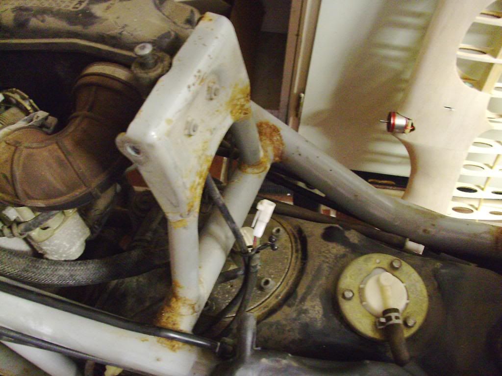 |
|
|
|
Post by erik on Feb 12, 2014 21:26:42 GMT
Hi All,
Hope one can shime in to an other problem I need to solve. The side stand switch and seat switch anr not the mechanicaltype I expected them to be. Unfortunetaly, the manual doesn't explain how to bypass these kind of switches. There are magnets inside. Can I simply bypass these switches and fool the system? If not I'd welld theminsidethe chasis and block the switch pressed in permanently.
The hand brake switches are mechanical and easy to bypass. I did notice i needed to press in one of these brakes to start the engine. From memory I think it was the right side brake. As I am using the original bike switches it seems to me the richt brake switch connected to the brake pressure switch would light the brake lights and ables to start the engine? That would be great and simple. The left brake connector will be unused.
This evening i madethe starter wiring and connected the loom to the engine sensors. I'm happy the rear part of the loom fits perfect on top of the engine. I'm working my way forward and found the saddle switch...
Thx in advance,
Erik
|
|
|
|
Post by roger32849 on Feb 13, 2014 0:28:18 GMT
Erik
The white plug looks as though it might be for the storage compartment light. You would need to provide the wire colors for me to be 100% sure.
As far as the side stand switch, yes, you can bypass it. It is part of the safety circuit and works with the safety relay. My 2008 side stand switch has a resistor, but it is only used as a feedback circuit and has nothing to do with operation or safety if the switch is bypassed. My side stand switch was mechanical and used a spring loaded plunger switch. The side stand in the stowed position closed the switch.
Both left and right brake switches go to the same relay, either of them will turn on the brake light and either or both can be used to close the circuit to provide power to the starting solenoid. It would be a mistake to wire the unused connections together to bypass the switch. If you only use one set of wires as your starting/brake light circuit, cut and cap the other set, but do not connect them together.
Good luck on your build
Roger
Worcester Massachusetts
|
|
|
|
Post by edvb on Feb 13, 2014 0:53:32 GMT
Maybe this will help. Disregard the horn circuits on the bottom as I was trying a couple things out.  IMG_1406 IMG_1406 by evanbelkom, on Flickr |
|


 I think a tab on the inside of the forl may work as desired too. Need to have a closer look later, I had to outsource the fork assy for adjusting the caliper bracket. No big deal and if they do it neat I may reconsider to outsource the final welding to them too which is for me, a high risk because near everything oursourced on the tR1ke was done in lower qty as expected.


