|
|
Post by James on Oct 23, 2014 20:02:26 GMT
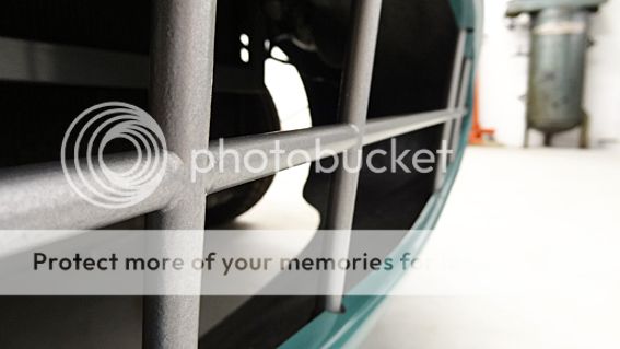
We used the bunch of steel rods that were supplied with the kit. We built it flat on a sheet of ply with panel pins holding everything in shape to start with. I cross-halved all the joints first with the grinder and then bonded the whole thing with liquid steel two-pack putty - fettling the joints approximately as they cured and then leaving for a few days to cure solid. An hour with files and abrasives had the grille looking great. Neither me or Larry are brilliant welders but I recon you'd be hard pushed to get it that neat any other way. It's also completely rigid. Good stuff. Few coats of primer and then several coats of wheel paint. Every point is bonded to the body so it would take a pretty good kicking, I recon. |
|
|
|
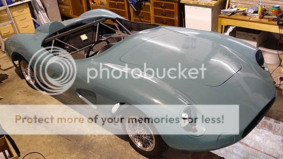
Post by James on Oct 23, 2014 19:50:06 GMT
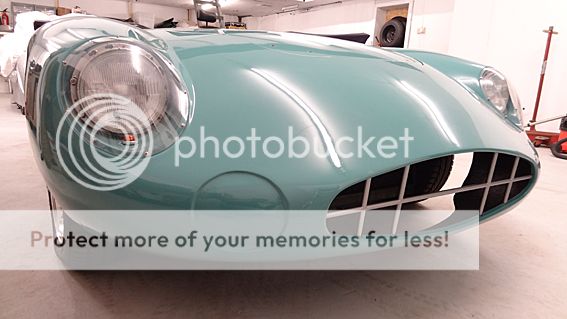
Front Grille fabricated and installed. |
|
|
|
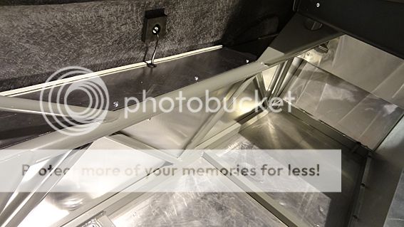
Post by James on Oct 23, 2014 19:47:07 GMT
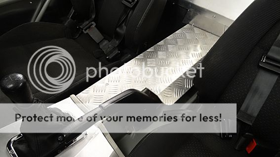
We decided that the handbrake cable and fittings were unattractive and potentially dangerous as exposed parts. Some time with some thick alloy checkerplate fabricating a cover made a positive addition to the interior. All edges ground off with a nice radius and polished up. Getting in and out is not that easy and being able to clamber around on the tunnel makes for an easier life. |
|
|
|
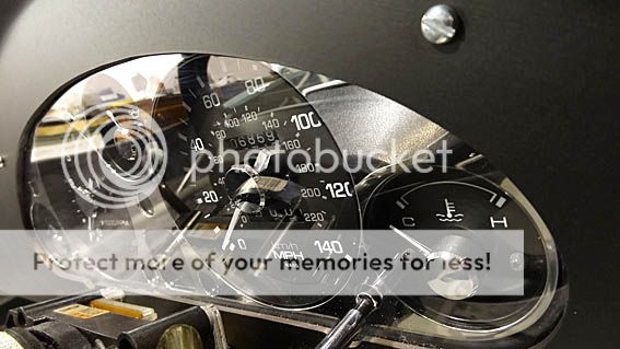
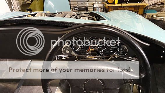
Post by James on Jun 18, 2014 20:59:19 GMT
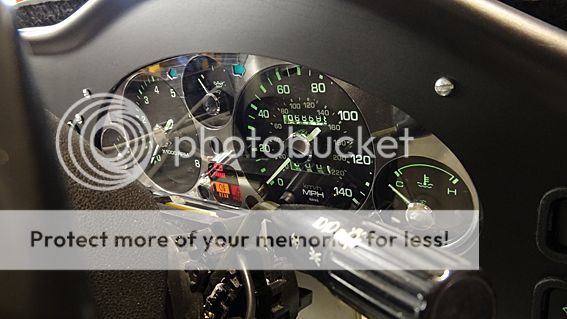
Dials illuminate and dim nicely. Tell-tale lights working. But here's two questions which you could help us with if you have the time;
1. The winkers on hazard have a nice steady rhythm but when just working normally, left and right, they are a bit frantic. All three are working on each side. Any suggestions?
2. Will the tell-tale rear fog lamp light in the cluster be enough for IVA or do we need to install a separate tell-tale light next to the switch itself?
As ever, any help you can give us will be most gratefully received. Thanks.
We're sending off the IVA booking form this week! 
|
|
|
|
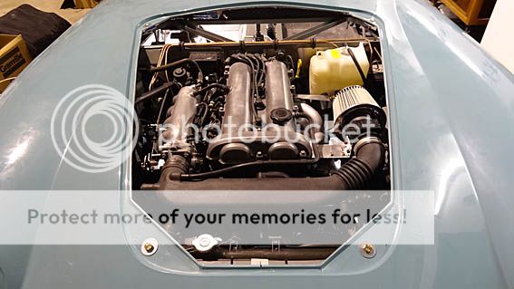
Post by James on Jun 18, 2014 20:49:43 GMT
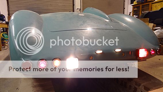
All rear lights work. The IVA fog and reverse are in position. The fog toggles correctly when the lights are switched off and on etc. The engine fired on the second turn after 18 months standing. Awesome! |
|
|
|
Post by James on Jun 18, 2014 20:46:10 GMT

Battery position and kill switch. Need to get a battery box. |
|
|
|
Post by James on Jun 18, 2014 20:44:16 GMT
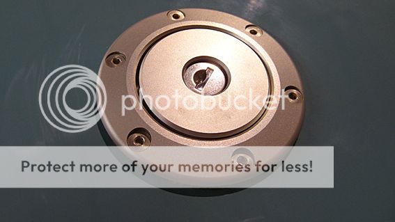
Not ideal but not minging. The IVA filler cap is installed and operational. Get a full meter length of the most flexible fuel hose you can buy. It might be expensive but you need wiggle room underneath to get it in position. I wasted money on a budget half-meter and had to re-order after giving up. |
|
|
|
Post by James on Jun 18, 2014 20:40:17 GMT

Larry made a nice job of the rear bulkhead using planks of wood and clamps on the bench to get some pretty good straight bends in the ally sheets. |
|
|
|
Post by James on Jun 18, 2014 20:37:20 GMT
Horizontal section fitted to side panel showing the grommet, wiring and fitting for the side repeater. We chose a high position after seeing original DBRs using high side lights to illuminate the car numbers for night racing. The square foam is there for IVA.
|
|
|
|
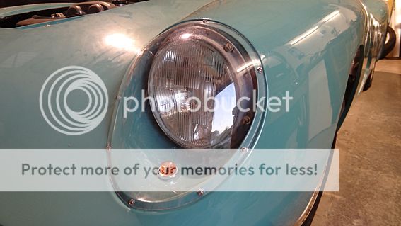
Post by James on Jun 18, 2014 20:33:07 GMT
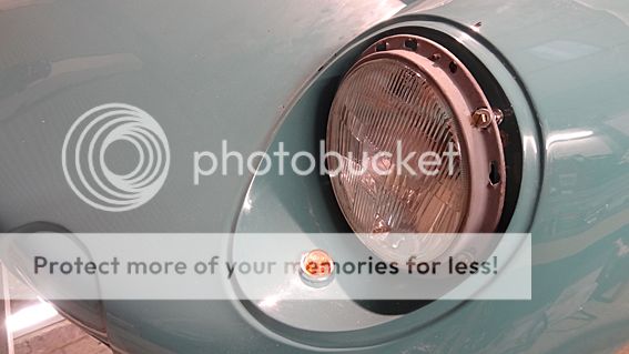
Front winker in place with a bead of silicone. We drilled a small hole at the back on the bottom of the headlight recess as a drain hole for water ingress. The headlight is attached using springs/rivnuts and locking nuts on the rear to allow for adjustment.
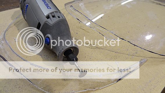
I found the Dremmel to be a good tool for the headlight cowls. Once cut out roughly the material is quite flexible. Mark a spot on top centre of the cowl and on the body where it marries, then keep pressing the cowl into place and marking areas to trim. Give yourself over to it for an hour or so and it will eventually drop nicely into the recess. Sand the edges and then drill for fixings.
I used M3 rivnuts epoxied into the bodywork. Be careful of the angles you drill. Work out where you need your fixing to end up as the recess 'overhangs' sharply at points towards the top.

Side panels in place. We decided to fit it in two parts - the upright, and then, with the use of 90 degree angle along the top, the horizontal section using screws so that they can be removed for access.
|
|
|
|
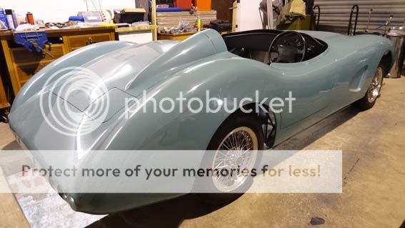
Post by James on Apr 6, 2014 17:04:42 GMT
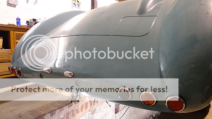
The lights installed, minus the reversing light and foglamp. We really don't want a line of four round lamps and so I have ordered IVA-compliant rev and fog lamps that (hopefully) will be slung beneath the car for the test. IVA states that the fog should not be within 100mm of the brake light and should be a min of 250mm off the floor. It will be tight. I'm beginning to hate the test requirements but i'm sure it will be worth it. I am considering paying for a professional pre-IVA inspection as it's our first time. We'll see how confident we feel - failure is expensive. Build cost so far in total (including all replacement donor parts, powder coating, wheels, some new tools, consumables, the donor car itself etc. etc.) has just gone over the £10k mark. Working on the headlight mountings now, the filler cap (again). Then we can fire her up. Just found out that the 'plug and play' IVA OK filler cap I have just bought wont pass 'cos it has to be permanently tethered to the car. Brass wire is called for, I suppose. I'll let you know how we get on. Keep on trucking fellas!
|
|
|
|
Post by James on Apr 6, 2014 16:40:11 GMT

The loom has been a challenge for us. Positioning, logic and the sheer size of it makes it quite cumbersome. The ECU is mounted centrally. The ABS controller is back-to-back with the ABS block. We are pretty much finished with the wiring and have only needed to make extensions for the lights and the handbrake warning light. We have used the instrument dimmer control, hazard switch and the rear foglamp switch from the donor. I don't think the rear fog will be allowed for IVA which is worrying as these switches have now been installed neatly into the dash. IVA states that the fog should only come on when dipped or main beam is on and that if the ignition is cut then the fog won't come back on until switched again with the headlights on. Our car didn't do that. Carbuilder Solutions have an (expensive) electronic module that you can insert into the loom. I've ordered one. |
|
|
|
Post by James on Apr 6, 2014 16:20:11 GMT
More fabrication at the front of the sill. We have chosen to split the cockpit sides into the upright section and a separate flat top. You can see the 90 degree bracket running along the top. Rivnuts will be used to allow access into the side cavity. |
|
|
|
Post by James on Feb 23, 2014 14:26:57 GMT
Hi R2S. Np4wicked is right - there is no room above the tank for a wheel and dependent on how the exhaust ends up - I suspect a spare might not be possible in that 'boot' area either. I think there's an IVA test station in Carlisle? Aston fuel caps might be a non-starter for IVA so I've bought a lockable 'aircraft'-style flush one with unleaded insert. I will have to replace later and sell the IVA one. However, it might look ok? I'll fit it this week and let you have a look.
Hi Gwnwar. Yeah, I know they look small. I couldn't afford the 15" chrome rims that Stuart has used. These are some Eunos 14" wires that we picked up with good tyres for about £200 all in for four on Ebay. I like the alloy look better than the all-chrome but I know they should be 16" with spinners and nice high Avons. For IVA we'll use the original alloys and tyres from the donor so that all instrumentation stays relevant. Post IVA we want to try putting the highest possible tyres on our wires and see if that fills the arches better. If not, sell 'em and save up, I guess.
Here's some sill pics from our last session :-

Looking down from the cockpit edge you can see the back of the seven rivnuts that we used to attach the sill to the tub.

Countersunk stainless fasteners used on the exterior. It's a two-man job to marry the elements together but it is satisfying because the resulting rigidity in the car is enormous. It suddenly feels like steel. We think we might brace the rear-end wheel arch inwards to give some extra tension and rigidity in that area too - and to echo the nice curved sides that we have achieved. |
|
|
|
Post by James on Feb 9, 2014 17:36:27 GMT
Right here we go ... this is what we've learned about getting the body on - which was, for us, quite a long process of fit and refit of the dash, it's components, the body, steering etc. before we got it something like. This is how I recommend you go about thinking about it.
First decide what instrumentation you want on the dash. If, like us, you want to use the panel of dials from the donor then you need to start from this point as it effects everything. Stripping off the old façade of the instrument panel is best done with a Dremmel tool or similar. Make a template of the flat face when you've finished and with some time and patience you will discover where to cut out the hole in the dash and where to drill for fixings. The pod of instruments must be as high as possible in the dash bulge and as far right as possible - really bang it up in there. I spent quite some time over Christmas doing this carefully at home, adding several after-market MX5 accessories to the instruments at the same time.
After I cut the hole in the dash I used a permanent marker to colour the edges back to black, fitted my own clear plexi cover and siliconed around the whole thing except for two places on the bottom to let it breath a bit (in case of condensation).
Now put your seats in and fix them. Then make sure your steering wheel position is as low and as far left as you can possibly get it and still be comfortable - really push it. This will all make sense in a minute. Now offer up the dash and pull it as far back towards the steering wheel as possible and cut a recess in the bottom of the dash to allow the dash to go as low over the column as possible. If the dash is too far forward the body will rest on top of the instrument bulge and you want the body to be as low as possible to try and get it to meet the sills. The only satisfactory way to have the instruments is central to the wheel and the bulge - hence the positioning suggestions made earlier. Even with all that, the dash, when aligned nicely with the wheel, will still be off-centre towards the right by a couple of inches. We decided this was acceptable given the imperative to see the dials nicely. Make some brackets to fit the dash onto the space frame in this position and flat to the top of the space frame.
The wheel, display and bulge now all line up pretty well while minimising the drift to the right of the whole dashboard. If you intend to use separate Smiths dials or the like you should still consider a lot of what has been mentioned. We have the body banged right down on the dash now with that flat to the space frame and we're still (bizarrely) higher off the sill on the right compared to the left. However, other measurements and visual confirmation says we have the body nice and flat across the car.
We were happy enough to fix it permanently and we made brackets for the front first in the corners of the bonnet.
These were fixed to the front top rail above the radiator and gave us a finite positioning so that we could work on the back bracket.
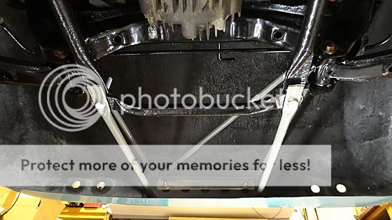
An hour or so of measuring and drilling got this nice and rigid and fixed through the rear number plate recesses. We made a long aluminium plate to stretch between the two body bolts. All body brackets have been cushioned with high density foam pads where they meet the tub and then tightened right up to compress.
The wheel positions were checked throughout and the arches meet up well. You can just see here how the sill will have to bent up quite a lot to fix onto the tub.
No matter what trials and tribulations you go through, this car keeps on giving back in spades! We're on the last stretch now and we can't wait to get going. Sorry we're taking so long!
|
|


