|
|
Post by nitram on Oct 1, 2014 16:51:25 GMT
Good alignment is for wimps and the extremely lucky ones. I wrote in my build: As forecast by numerous builders, it doesn’t fit. This did not come as a complete surprise. The rolling chassis is held together in the middle by a couple of bolts at either end of the PPF; any small deviation at one end will produce a magnified deviation at the other. More significantly, the rear sub-frame is held on by a couple of studs going through the diff bushes and at the other end the sub-frame is connected with a couple of rubber-mounted engine studs. The longitudinal variations can be enormous and added to by the two sub-frames tilting at different angle depending on whether the rolling chassis is on its wheels or any one of a number of jacking points. There are an infinite number of banana, snake, snana or banake combinations. The only thing that holds the rolling chassis straight on the mx5 is the body and the only thing that will hold it straight on the Exocet is the mev chassis. After the disappointment of finding that my infinity to one chance of a straight rolling chassis had not come up, I loosened the PPF and sub-frame bolts – there are not that many. The chassis, with a bit of persuasion, can then be made to un-banana, un-snake etc and the holes can be made to line up. I bolted the exo to the sub-frames and only then went back and re-torqued the bolts that I had previously slackened. Trial fit over, I take the exo off but do not disturb the rolling chassis in its “straight” position. Read more: mevowners.proboards.com/thread/3069/nitrams-build?page=2#ixzz3EucPqFC5I also describe how I had to make up a couple of mild steel "joiners" to get the two tabs connected. Mine was a Mk2 '99 donor; I get the impression that those who used the Mk1, found the fit a bit easier. |
|
|
|
Post by gnc on Oct 1, 2014 20:50:05 GMT
Mr Jingles, it looks like we're not too far off horizontal. Thanks for the suggestion. We'll lower the front a touch and see how she sits.
Nitram, I've just had a good read of the early parts of your blog. Not only very informative but also rather hilarious at the same time. What a great write up. So glad it's not something we're cocking up, we had begun to wonder!!
|
|
|
|
Post by mrjingles705 on Oct 1, 2014 22:43:45 GMT
Interestingly (and I'm not sure why I forgot this, since it was right in front of me in a pile of bits!) the mevster kit has a bridge plate for fitting onto the wishbone; replaces the existing span. I've asked Stuart for some more details on his particular implementation ... I don't want to chop these things willy nilly! You can see a before/after here: 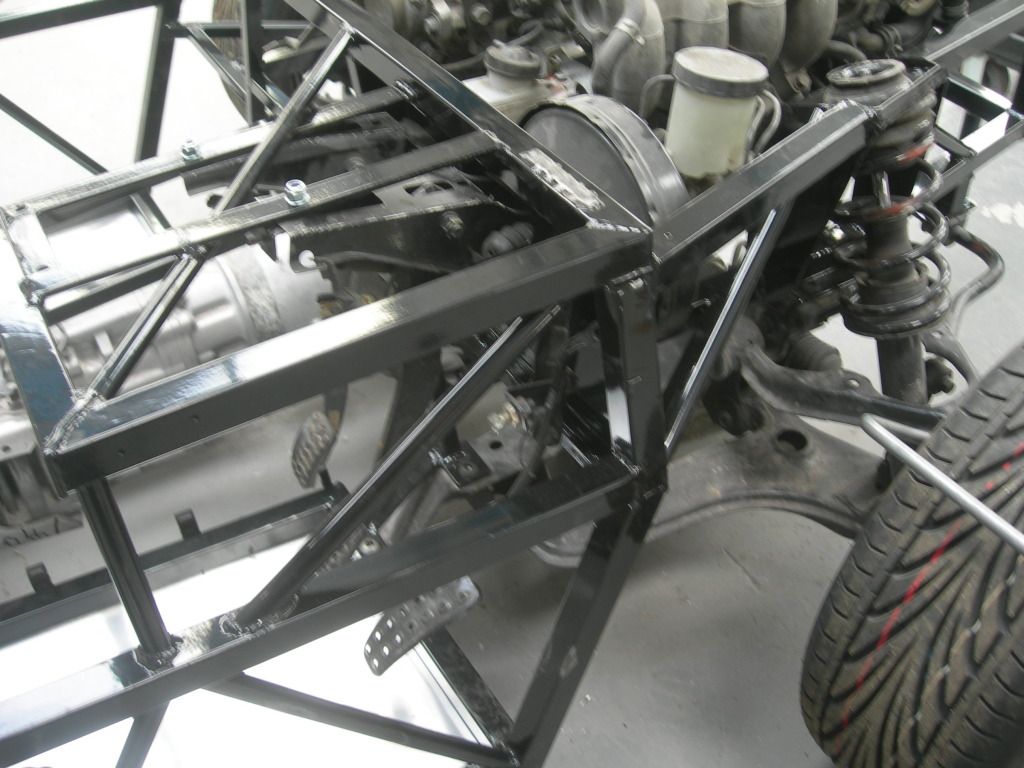 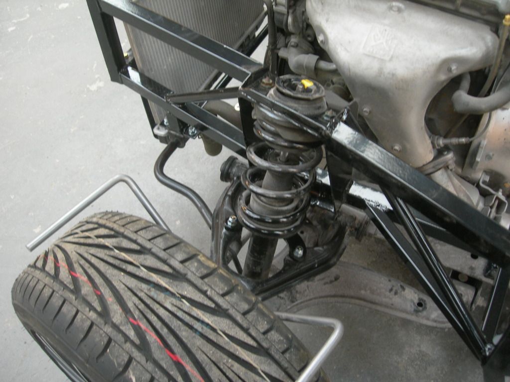 |
|
|
|
Post by gnc on Oct 3, 2014 21:52:34 GMT
The steering wheel was next on the agenda. Several attempts were made until we got things right. Firstly, we cut away the tabs on the back of the brake/accelerator plate. This allowed the clutch to be mounted flush with the bulkhead and all the pedals then lined up. We then trial fitted the steering column. Everything mounted nicely at the steering wheel end but... by removing the lugs on the brake/accelerator, the mounting points for the steering wheel on this plate and clutch pedal plate are too far towards the front of the car and the splines going into the steering rack joint are approximately 20mm too far forwards. Everything back off again. The tabs were re-instated and two 4mm thick washers used on the bottom two fixings to get the correct angle on the pedal. The same was added to the top two fixings on the master cylinder to keep the angle congruent. To keep the clutch pedal aligned, the rear of the lugs needed to sit flush with the bulkhead. We manufactured a plate to sit over the lugs and give a good anchor point for the clutch master cylinder to fix against. 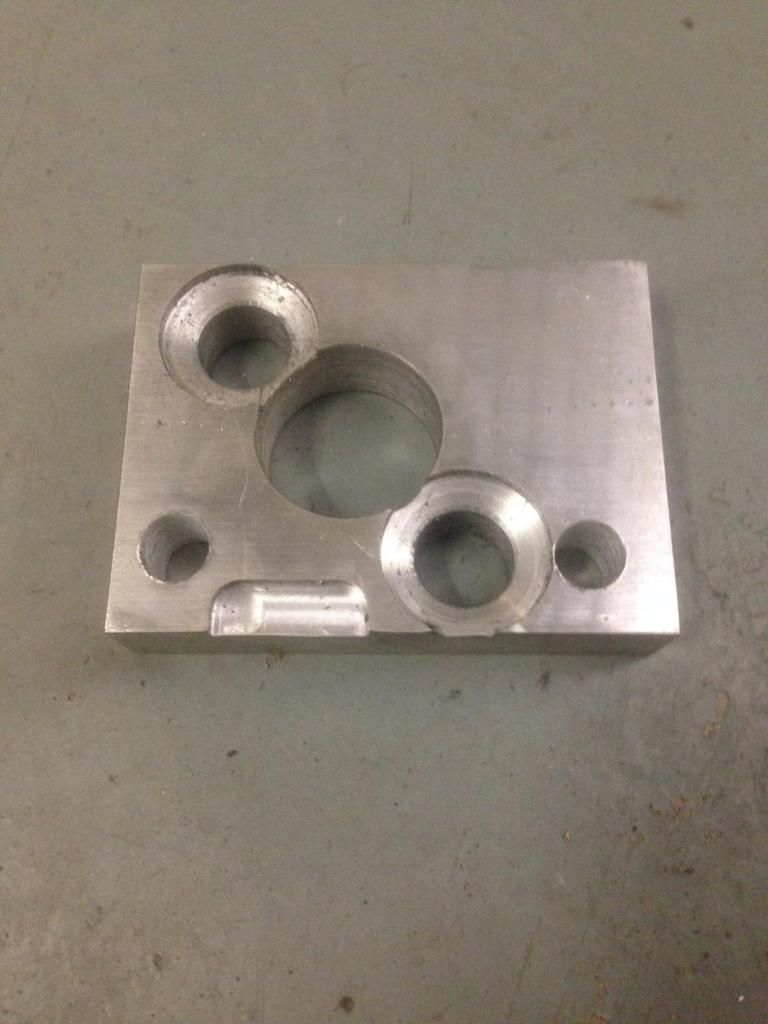 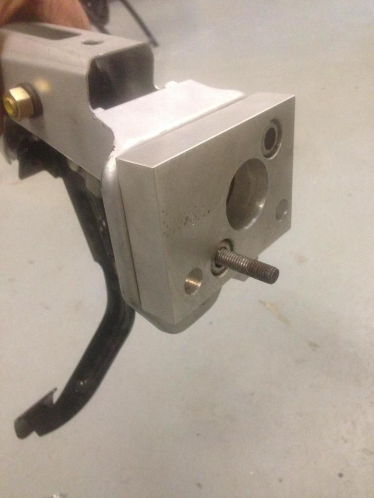 When mounted in place, this gave a very solid fixture. 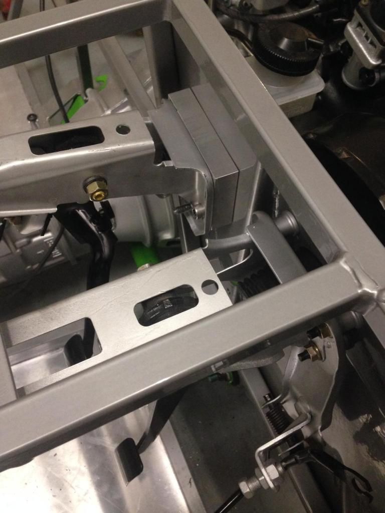 Next the steering column was separated, masked and painted. Whilst this dried, the shroud for the steering column was located, drilled and a spacer made for the outer lug. 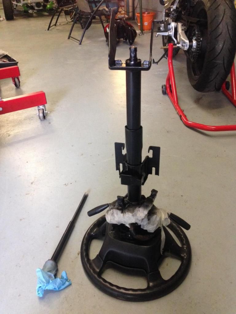 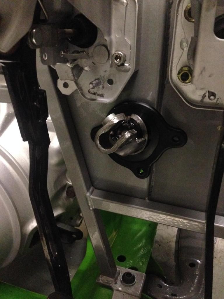 The column was all re-assembled, located through the shroud and gently eased, with the aid of some copper grease, back into the coupling. The column was loosely bolted, aligned so as to ensure good clearance within the shroud and then bolted tight. This whole process has been a little more involved than expected but we now have a rolling chassis that can be pushed, pulled and even steered around the workshop. 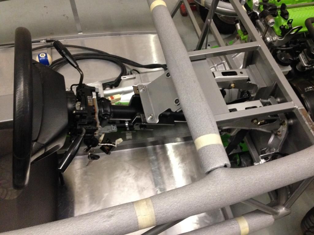 |
|
|
|
Post by jgilbert on Oct 3, 2014 22:46:28 GMT
Nice spacers.
Don't forget to bolt the top of the pedal assembly to the chassis plate above as per the build guide. Lots of leverage otherwise on those pedals.
|
|
|
|
Post by gnc on Oct 15, 2014 20:10:32 GMT
PJ has made some rather nice bobbins to go above the pedals for support when fastening to the upper brace. 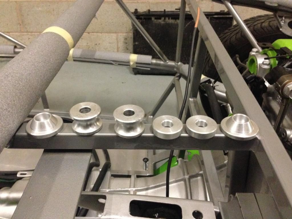 Alignment of the hole for the clutch pedal fixing point was a little to far forwards so we drilled a hole further into the brace and used a spreader plate under the clutch pedal. The top spreader housings may well be used for additional fixings further down the line. 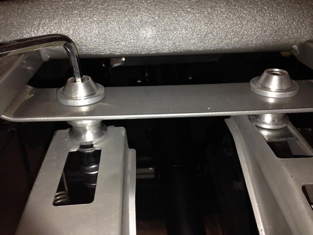 We also noticed it was getting a little colder in the mornings so had a nice new gas heater fitted to keep our little Exo warm and frost free over the winter months. 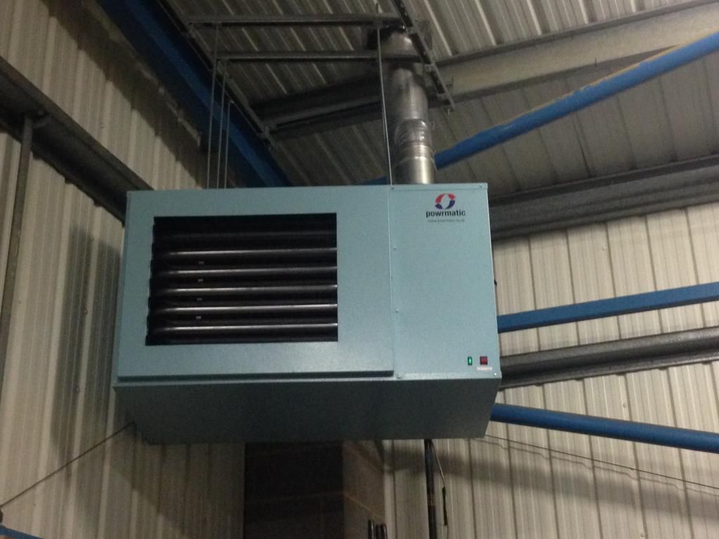 Not much more to report at the moment, the exhaust manifold has gone to be shotblasted along with the two anti roll bars which will be powder coated satin black. Until then, we cant really position the ABS assembly so have just made a little start on the fuel pipe runs. |
|
|
|
Post by gwnwar on Oct 15, 2014 21:40:59 GMT
Nice heater unit.. Might want to install a couple of overhead fans to push the hot air down.. Or run them in reverse
pulling cold up and hot down the wall to spread heat.. I have 2 wall unit with fans in my work space 60'x45' work great..
|
|
|
|
Post by gnc on Oct 19, 2014 9:39:50 GMT
Still waiting for parts to come back from the powder coaters so just tidying up a few unfinished parts for now. Decided to get the handbrake sorted and out of the way. Drilled an inch hole in the rear tunnel allow the offside handbrake cable to reach its mounting. Had to enlarge the fixing holes slightly to get the cable mountings to fit. Held the handbrake assembly in roughly the desired position and drilled the three mounting holes. The angle of the lever wasn't too great so had to make yet more bobbins to hold the mounting plate vertical and square. With these in place, its a simple bolt job and a tension of the cable. Handbrake..... DONE (almost). Just need to get a suitable grommet to fill the hole in the rear of the tunnel 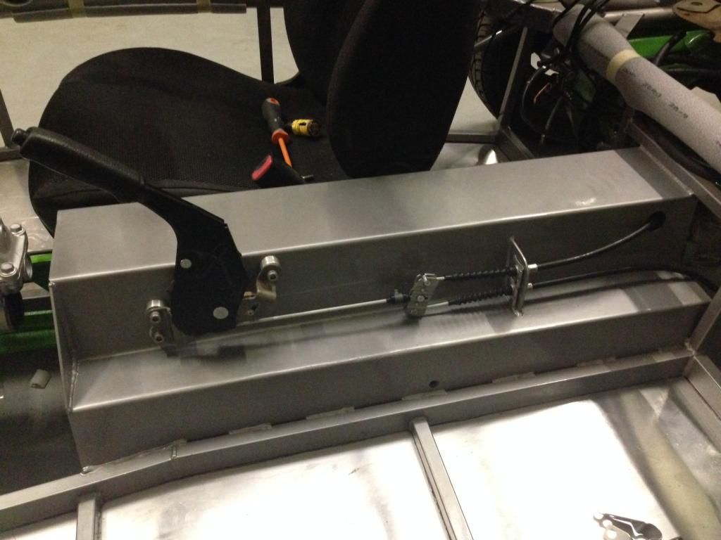 Bobbins were angled to match the side of the tunnel, cable position and alignment seems better in relation to the two rear cable mounting holes. 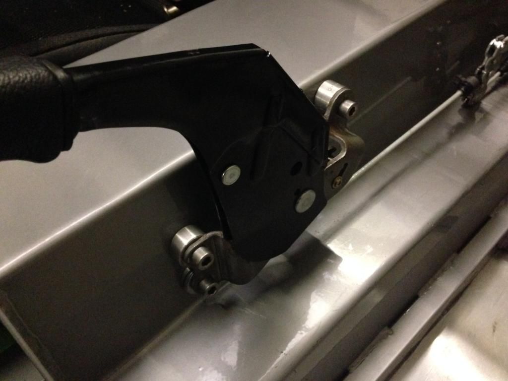 . |
|
|
|
Post by gwnwar on Oct 20, 2014 4:52:40 GMT
Hand brake looks a lot cleaner that way.. Good job..
|
|
|
|
Post by gnc on Jan 1, 2015 22:29:03 GMT
Firstly, we would like to thank everyone who has helped and contributed along the way in 2014, or even just popped in for a look, and to wish everyone a Happy New Year and all the best for 2015 !! Apologies for the rather prolonged absence in posts, I'm afraid to say that work rather rudely interrupted any progress on the car for the last few months, weekends included !! Spent a few hours over the Christmas interlude simply trying to remember where on earth we had got to with the build and what was needed next. It was decided that a little more needed progressing on the engine bay side so the next logical step was to look at the radiator. Took the mountings from the old MX5, cut them to size and welded them to some box section to give the right height for locating the radiator into. At the moment they are missing the ordered end caps to fill the box section. 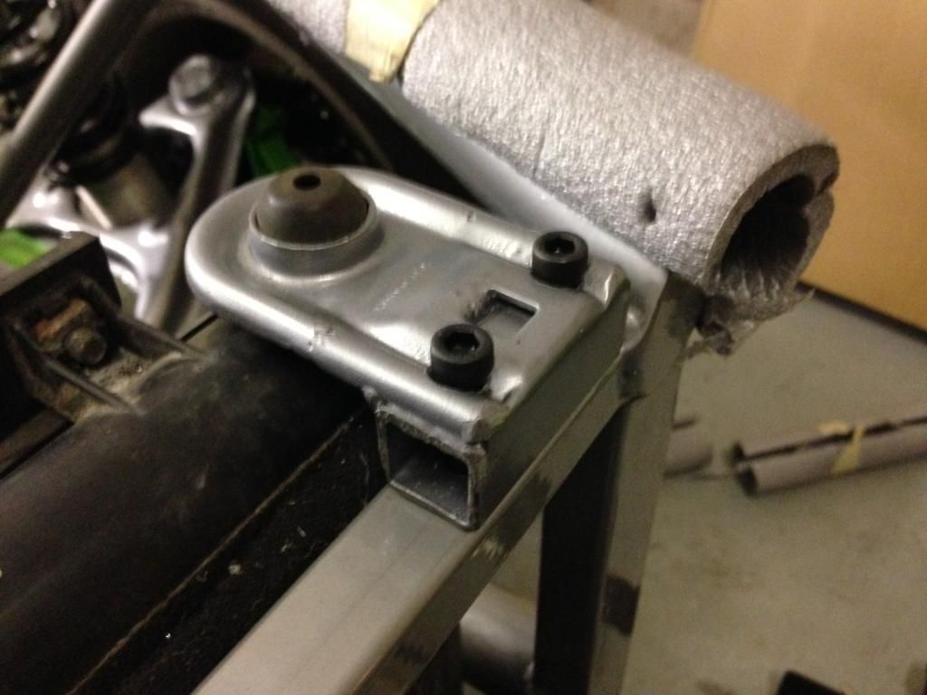 The cap head bolts will be replaced with countersunk stainless screws when the suppliers re-open. Another pair of mounting brackets were ordered from Ebay. These were needed to make the bottom brackets in a similar style to the top. The bottom of the radiator mounting was 170mm below the lower chassis member so needed a couple of brackets fabricating to suit. These were done with box section top and bottom but to prevent any air restriction to the radiator, two side plates were used rather than one central column support. When complete and the alignment was ok, these were welded to the chassis to give a permanent lower locating position. The first picture isn't too clear but shows the side profile of the bracket. 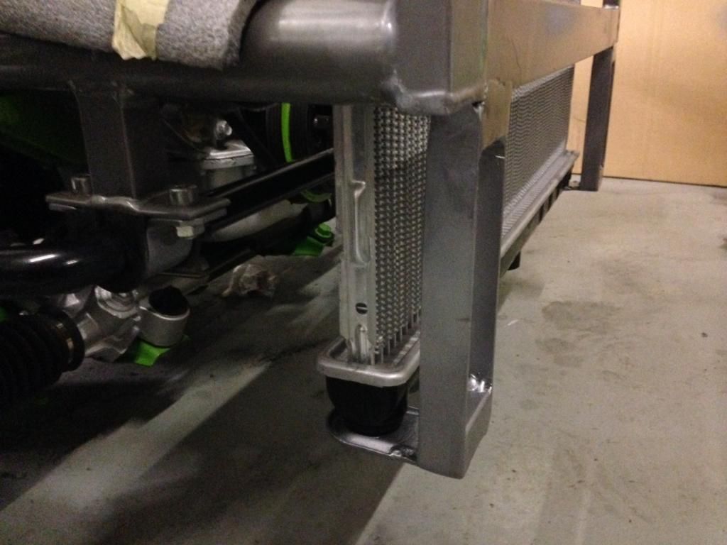 From the front there is very little in the way of profile to restrict cooling. 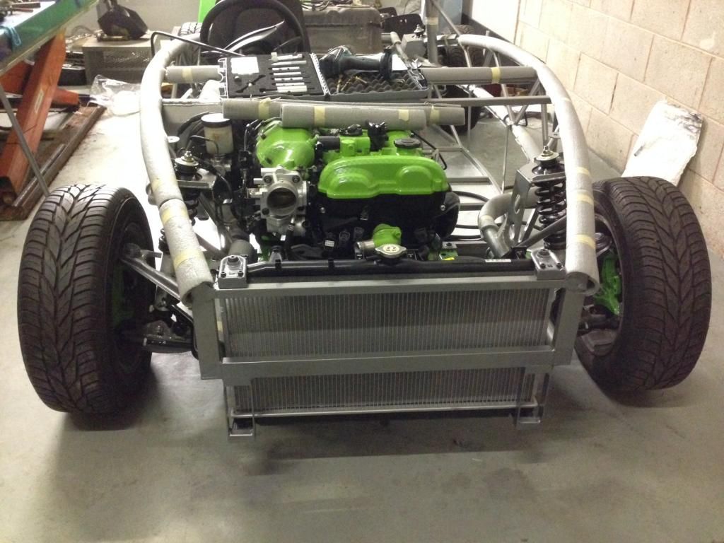 Hopefully there will be some more steady progress to come. Onwards and upwards..... |
|
|
|
Post by gnc on Feb 5, 2015 23:24:38 GMT
With the radiator fitted we have decided to try and finalise the fuel line runs into the engine bay. The decision was made to reinstate the charcoal canister and we needed somewhere to mount and a suitable way of fixing. An area of space seems to exist at the offside just behind the radiator so we set about making a removable bracket. 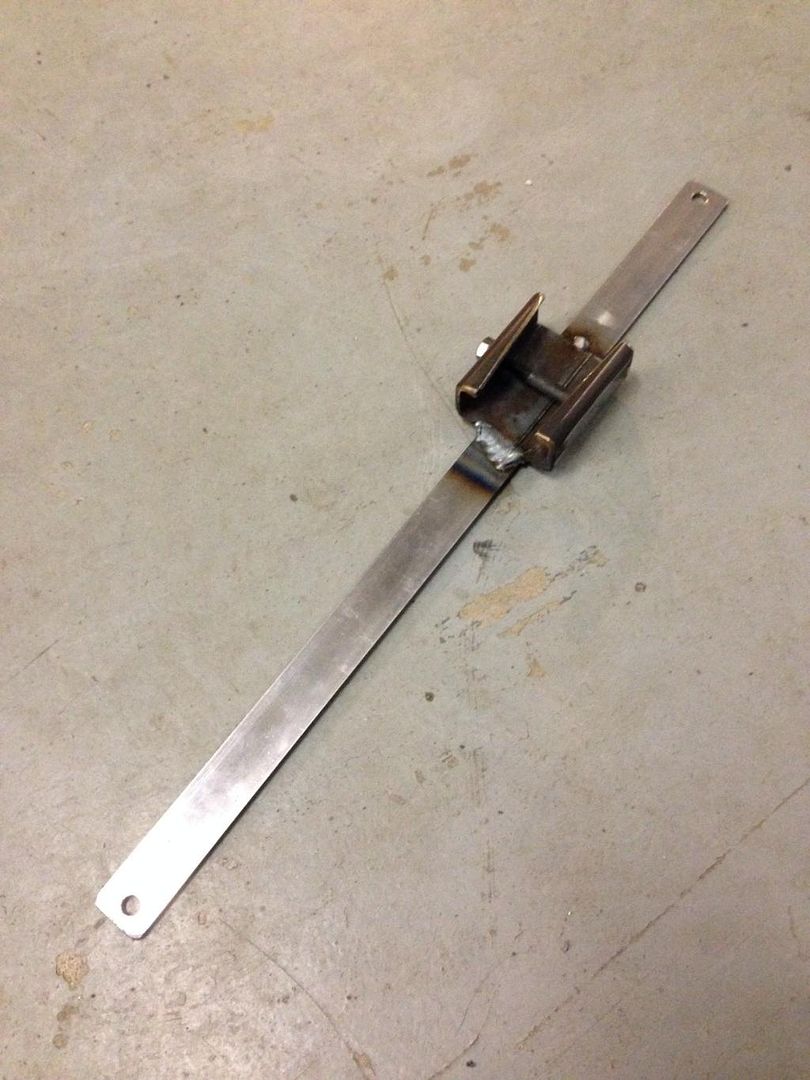 This was cleaned up, sprayed and mounted on the rear of the radiator. 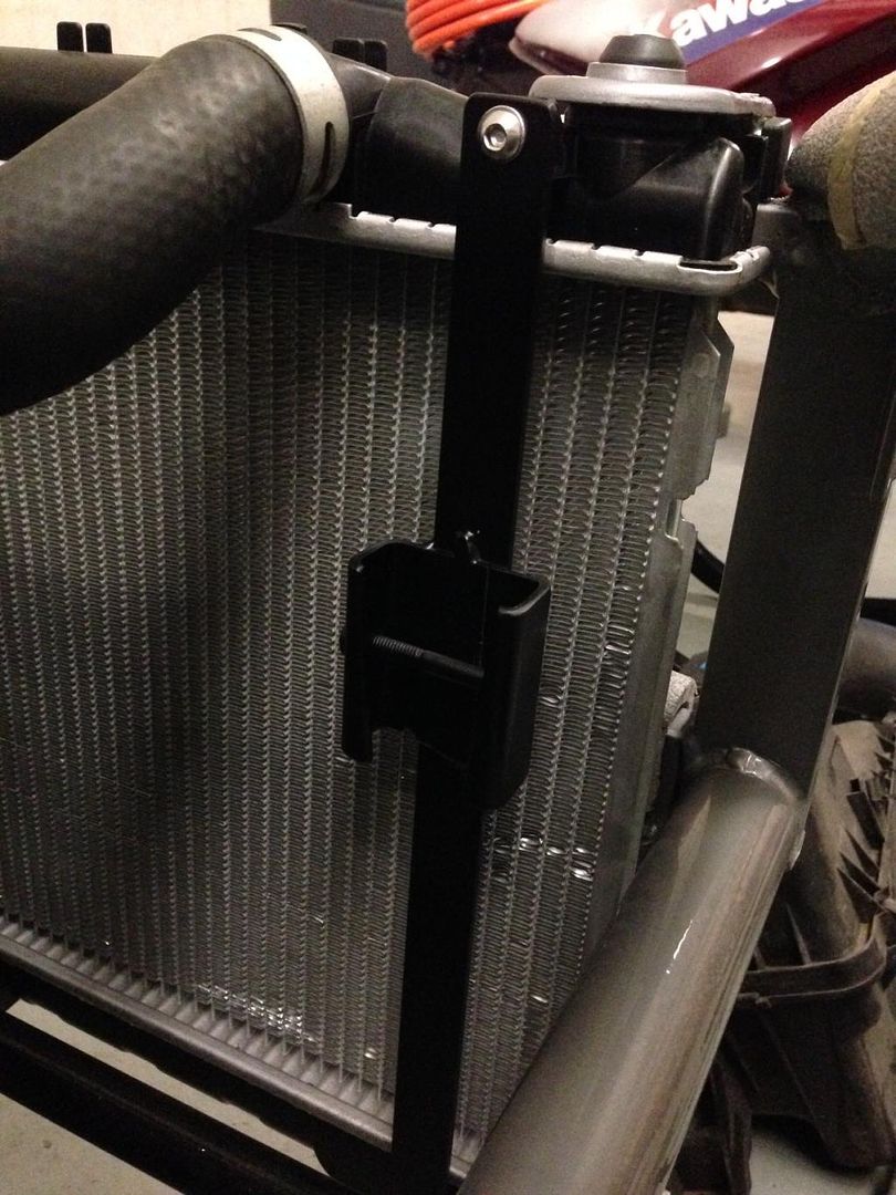 The charcoal canister was installed and clamped ready for the lines to be fitted. These were routed, clamped and spaced where possible and a few more spacers ordered to give additional spacing from the ppf/gearbox area up through the engine bay. 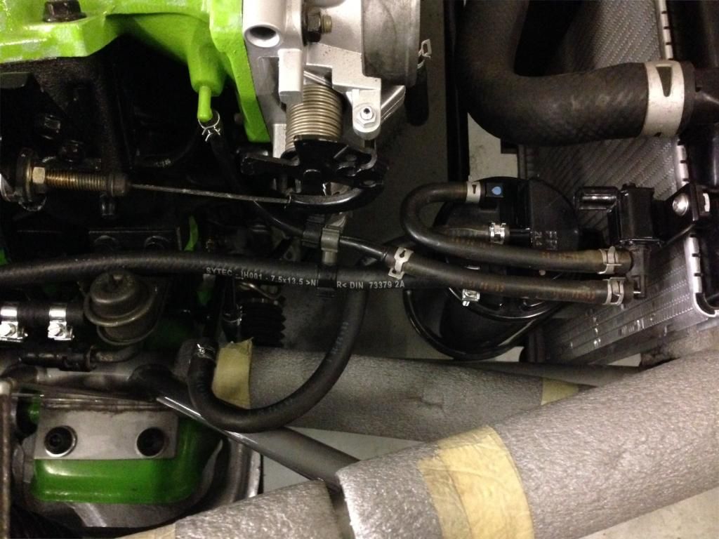 All looks well proportioned with plenty of clearance behind the radiator. 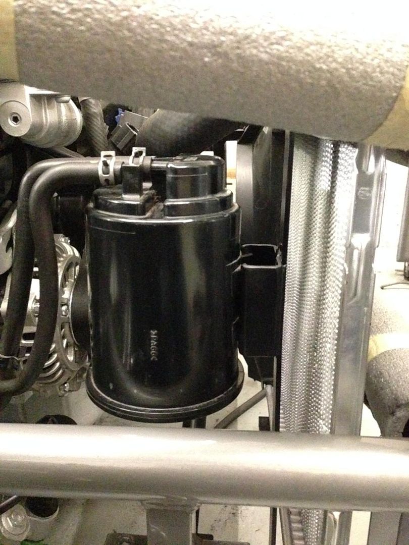 |
|
|
|
Post by jgilbert on Feb 6, 2015 18:24:30 GMT
Nice bracket design. Just wondered why you have fitted the charcoal canister? Most people in the UK remove them.
|
|
|
|
Post by greg on Feb 6, 2015 19:23:54 GMT
Nice bracket design. Just wondered why you have fitted the charcoal canister? Most people in the UK remove them. NB cars will throw a CEL with it removed. |
|
|
|
Post by tehjeffman on Feb 6, 2015 21:36:56 GMT
Nice bracket design. Just wondered why you have fitted the charcoal canister? Most people in the UK remove them. NB cars will throw a CEL with it removed. LOL at caring about CEL lights. Just pull the bulb out or go standalone. Just register your car in a state that has kit cars registrations or as a "show car". Edit sorry just noticed this is a UK car. |
|
|
|
Post by gnc on Feb 11, 2015 19:05:28 GMT
Re. the charcoal canister, it was put there for a reason by Mazda so we thought it might be a good idea to have it back in place. Nothing more than that really, and we weren't sure if there would be any consequences from having it removed.
|
|


