|
|
Post by eulaca on Oct 16, 2016 19:13:02 GMT
Hey, first post from me, I've been following your build for a while now.
The auto adjuster mechanism is removable, it just takes a little persuasion. You can put the old piston in a vice then screw a bolt on to it, and use something to pull or knock it upwards slowly.
I've also heard of someone using a long bolt that fits and a Knut, some pipe and washers to make an extracting tool. They used pipe the same diameter as the piston and turned the Knut to pull the adjuster up and out.
I don't know if you need to remove the inner circlip and spring (I did)
Hope this gives you some ideas.
|
|
|
|
Post by Fin on Oct 16, 2016 19:49:14 GMT
The auto adjuster mechanism is removable, it just takes a little persuasion. Hi eulaca. Good to hear from you, and thanks for the advice. I'll try something like your extractor tool and/or some kind of slide-hammer and see if there's any movement. Is the mechanism just held in the piston by friction then? |
|
|
|
Post by eulaca on Oct 16, 2016 20:02:09 GMT
If you type "mx5 auto adjuster" you should be able to find pictures of it under image Search. It took me forever to figure out it was called the auto adjuster, no one seems to acknowledge this part exists within the piston.
there's also an old thread on another forum where people are talking about ways to permanently remove them so they could disable their rear break. This might be worth looking at.
One of mine I managed to remove with my own strength, I've had to order a vice to get the other one out so it's sat on the side.
|
|
|
|
Post by h20boynz on Oct 18, 2016 8:41:15 GMT
That middle photo shows a circlip I think...though it doesnt have the little holes in the end you might expect, so not sure which type of circlip plier you might use. (Season this with salt as Ive not attempted disassembly of this myself  |
|
|
|
Post by Fin on Oct 18, 2016 9:20:25 GMT
That middle photo shows a circlip I think...though it doesnt have the little holes in the end you might expect, so not sure which type of circlip plier you might use. (Season this with salt as Ive not attempted disassembly of this myself  There is indeed a circlip, and a spring as eulaca above mentioned, both of which I have now removed, but the mechanism remains stuck. Will douse it in penetrating oil, and try to find a bolt that will fit into the shaft so I can exert some force on it, although it does seem a fairly coarse thread. Other drastic option might be with an angle grinder to try to notch the piston so I can crack it open - (last resort)! |
|
|
|
Post by Fin on Oct 22, 2016 18:35:25 GMT
Not the best of days, as I'd visions of assembling the sub-frames and getting the PPF and prop-shaft back together, so a rolling chassis would have been the goal. Getting back on the manual, after several weeks off dismantling, I noticed I'd forgotten about the mudguards and brackets. Figuring it would be easier to drill the mounts with the axles off, we whipped the discs off and gave the drive shaft an enthusiastic yank, only to dislocate the CV joint!! Trying to get it back in whilst still in the dust cover was like trying to thread a needle, inside a bag, with your eyes closed and standing on one leg. OK, I exaggerate - eyes open!
Took a while, and a charge of YouTube to learn that they were servicable, so off to buy some moly grease and a replacement metal band. Soon back in working order, which was a relief as I'd only just bought it as a replacement.
Next was figuring out how/where the mudguard mounts locate. Then came the realisation that there were no bolts included for fitting - guess I must be too naive. One of the holes seems to have to be drilled through the old mounting platform for the ABS sensor, which seems to place to nut (or bolthead) rather close to the toothed ABS cog itself. We also had to saw the ABS sensor off the front as it hadn't been previously removed due to bolt sheer.
Bit of cosmetic touch-up took us right into the start of the deluge, and so rain-stopped play as we had taken everything outside in vain hope of progress.
There's always tomorrow.......and Screwfix.
|
|
|
|
Post by p5curly on Oct 22, 2016 19:53:01 GMT
We had to drill out our fronts and I managed to re tap the thread back in
Then we lock tite the bolts back in
|
|
|
|
Post by tojeiro on Oct 22, 2016 22:23:55 GMT
Regarding the auto adjuster, the split ring on mine was free to move but it is very tight in the groove. Since the old piston is scrap the simplest way to get it out is to slit the old piston carefully in two places up to the split ring groove, preferably between the adjuster teeth. You can then break of the cut section of the piston and simply lever out the mechanism.
Never took any pictures but hope you can figure out what I did. As long as you go carefully with a cutting disc or dremel I found it much easier then any other method found on the web.
|
|
|
|
Post by Fin on Oct 23, 2016 9:22:08 GMT
Thanks for the advice tojeiro . I'm going to try to extract it once more today, and then get the angle grinder on it. Or some heat....... |
|
|
|
Post by eulaca on Oct 23, 2016 13:29:44 GMT
I've also had to resort to cutting the old piston open to extract the adjuster. The metal's quite soft and a jr hacksaw made easy work of it (until it went blunt). I'll hopefully finish the job today after buying some new blades.
|
|
|
|
Post by tojeiro on Oct 23, 2016 21:18:24 GMT
Heat won't make a difference as it is retained with a sprung split ring that sit in the groove about half way in.
The cutting allows you to press down on the split ring to release it from the groove.
The problem with pull out is the thread on the insert is a special coarse form that I could not find a suitable bolt for.
I spent 4 hours faffing on the first piston about before I thought of cutting the piston. The 2nd one took me 5 mins.
|
|
|
|
Post by Fin on Oct 29, 2016 20:24:51 GMT
Well, after several days of slow and methodical progress, it was time to take some giant steps. Things started badly as when tightened, the rear mud-guard mounts jammed into the toothed ABS cogs. Luke had to (literally) do some angle-grinding, and knock-off the offending corners of the mounts so they would secure and miss the cogs. 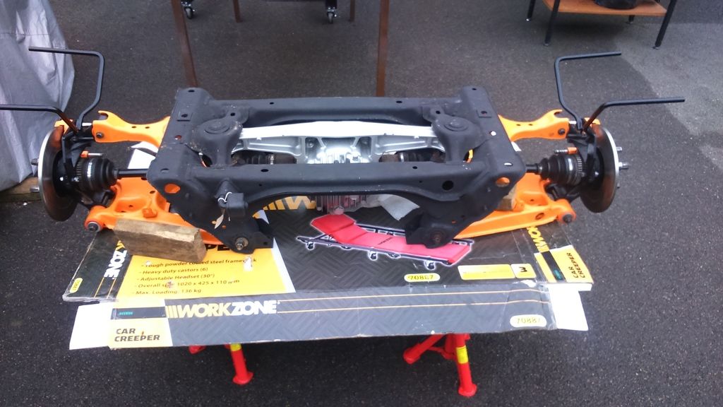 I finished off drilling out the sheered old dust-cover bolts from the front, and managed to clear three holes for each. The mud-guards were mounted using 4 M8s and 2 M10 x 40mm 1.25 pitch thread that I had to buy a box of 100 for. The other 98 will be heading for eBay, unless there are further surprises. 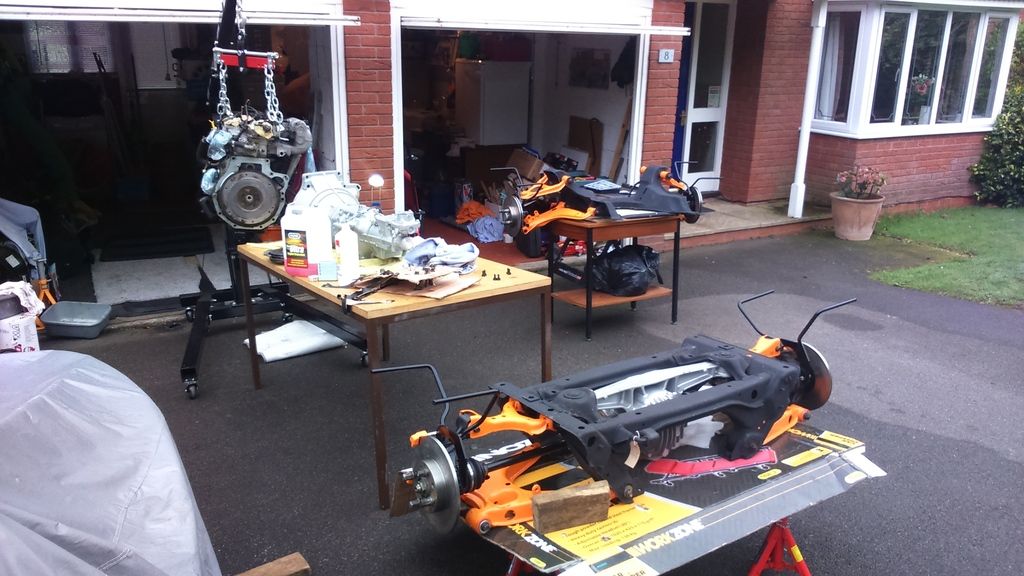 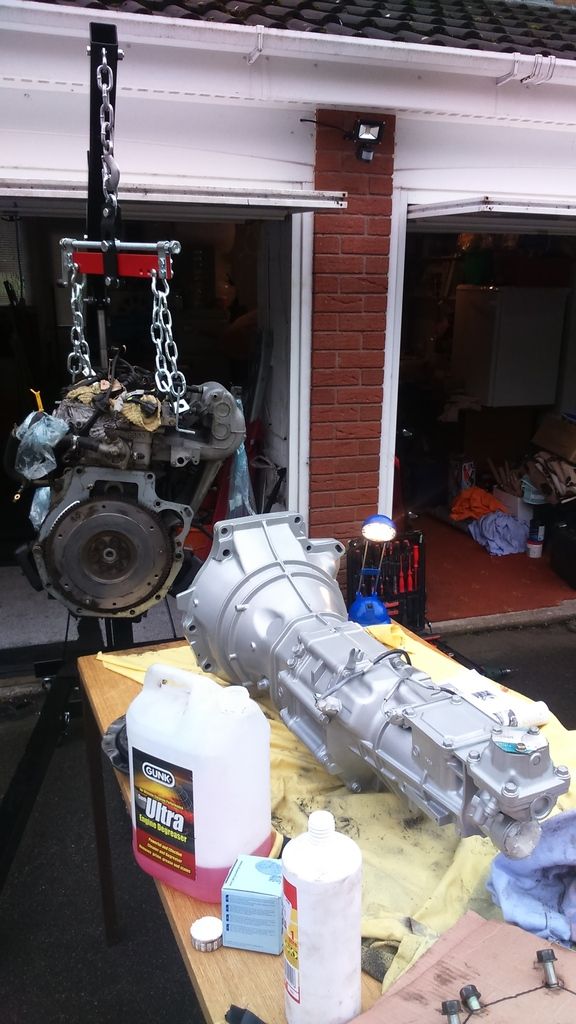 Time then to re-unite the engine and gearbox, so the clutch-plate was slipped in, and in the absence of a "mandrell" we lined it up by eye, and with blob of copper-grease, slipped the spline home and torqued up the bell-housing. So far so good. 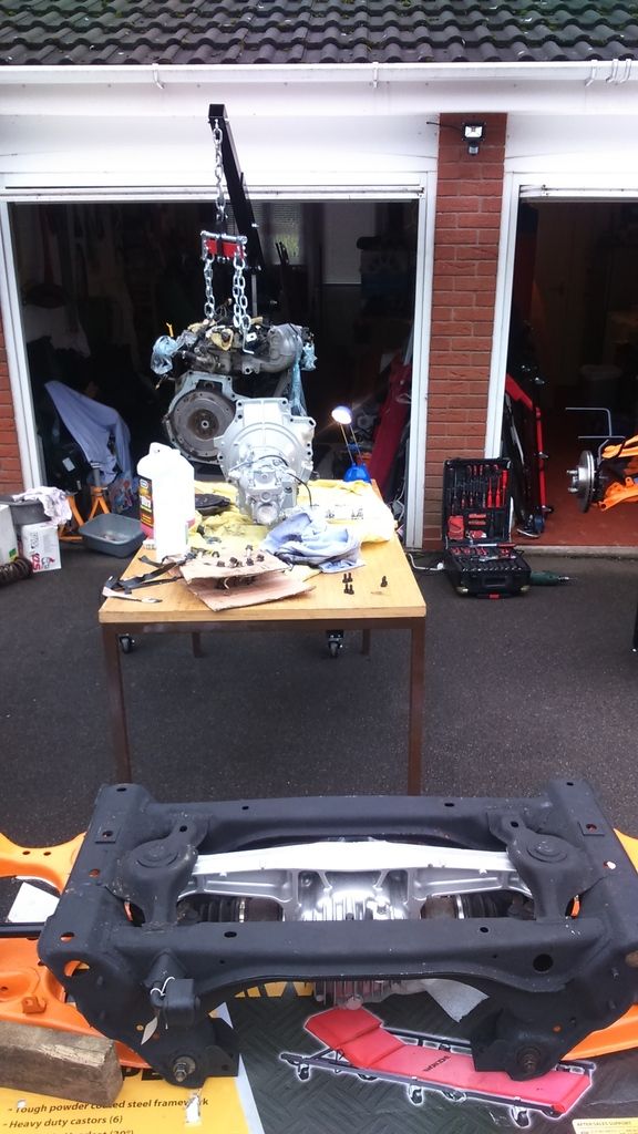 The exhaust manifold was slotted home, along with the starter motor, and then the whole engine was dropped into the cradle of the front sub-frame, and locked down. After that, we lined up front & rear, and introduced the PPF back into the equation, so for the first time it looked somewhat like a vehicle. Would have liked to get the wheels on, but I guess we need spacers now! 32mm seems to have been mentioned, but I'll explore tomorrow as darkness stopped play. Hopefully we can try the chassis tomorrow, and maybe even roughly mount the front & rear body to see it as it should be. All in all, a very good day. 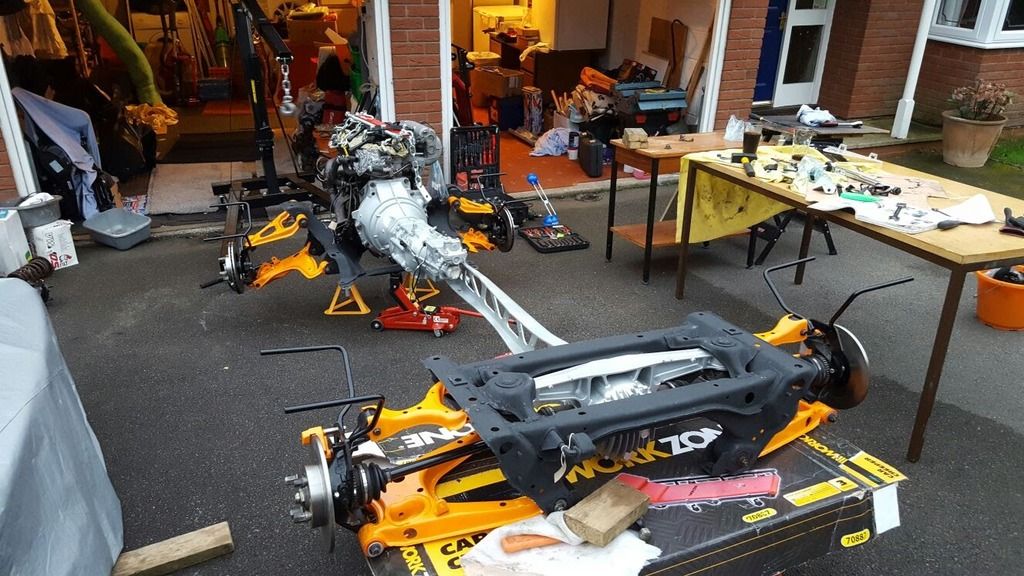 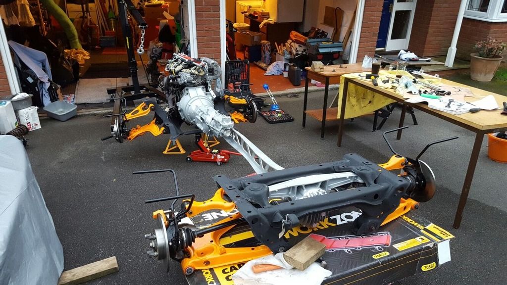 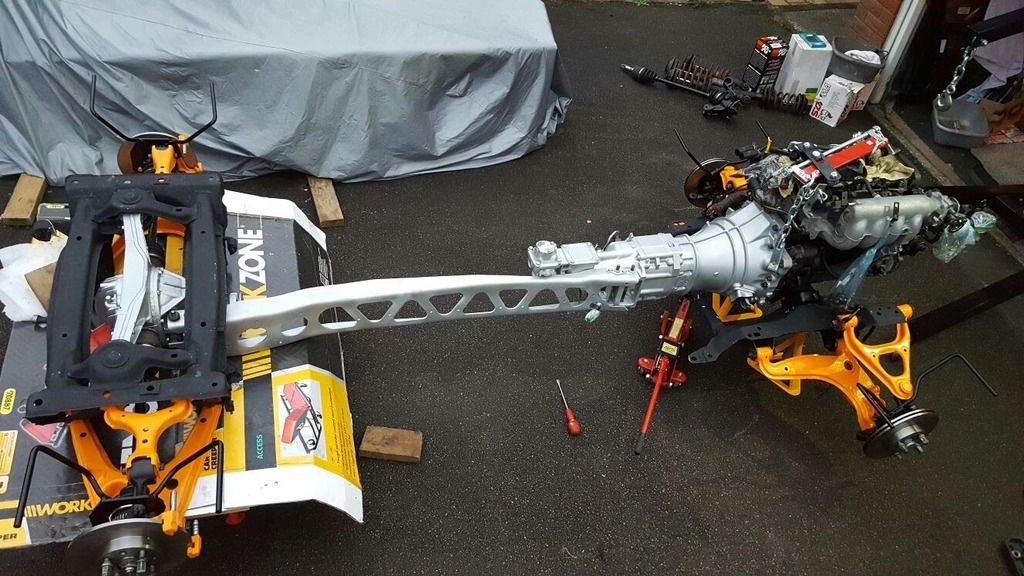 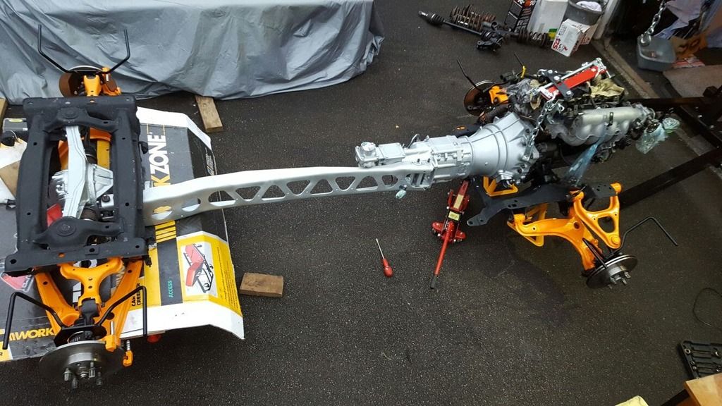 |
|
|
|
Post by johnp on Oct 29, 2016 20:54:58 GMT
I can't bear to look - it's all so clean! And if you can get under an Exocet with that slider I'll give up the viloin.
|
|
|
|
Post by Fin on Oct 29, 2016 23:19:03 GMT
I can't bear to look - it's all so clean! And if you can get under an Exocet with that slider I'll give up the viloin. Watch this space, Yehudi. |
|
|
|
Post by johnp on Oct 29, 2016 23:26:14 GMT
I can't spell his surname either - just noticed I can't spell violin.
|
|