|
|
Post by miket on Jul 3, 2015 18:10:35 GMT
hmmm - storage behind both seats and uses the excess cable - like your thinking.
Tho' whether a battery'll fit under my donor seats is tbd.
|
|
|
|
Post by miket on Jul 6, 2015 17:16:40 GMT
Moved on to fitting the radiator. I'd read about problems fitting it in so I removed the fan (and repaired a split in the plastic casing) and removed the side brackets. Removed a section from the brackets to fit around the chassis and so make them far enough apart to get the rad between them... 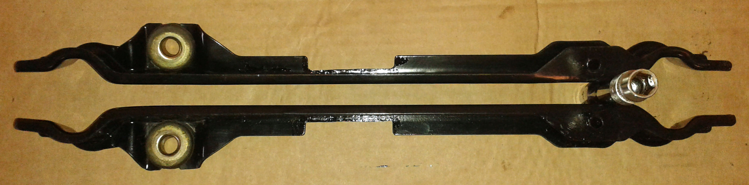 .. a bit of paint on the cuts and waiting for it to dry before offering it up to find the place to drill the chassis. |
|
|
|
Post by jwagner on Jul 6, 2015 20:05:30 GMT
|
|
|
|
Post by miket on Jul 6, 2015 22:03:26 GMT
From what I read on here it seems the UK & US cars' starting points and available extras are quite different now.
These brackets were on the donor rad and will be reused with bolts thru the chassis & the brackets' bushes at the top. These bolts will be the main support. Then a couple diy brackets at the bottom in support.
Other UK builders have taken different approaches. This is the approach proposed by the manufacturer, but the need to cut away some metal is an 'undocumented feature' that I found in someone's earlier thread. This forum's invaluable - as a rookie I couldn't have built this without the internet and this forum.
|
|
|
|
Post by Toed64 on Jul 6, 2015 22:20:24 GMT
Good plan: the MX5 rad is very flimsy without the side brackets, so a minor knock would do a lot of damage to the rad. I did the same as you. I bolted straight through the front chassis and bracketed back to the anti-roll bar mounts. Get the height right before you drill.
|
|
|
|
Post by gwnwar on Jul 7, 2015 5:10:29 GMT
If I remember right top of cap should be no more then 10mm above tops of frame rail..Tape a string on rails..
|
|
|
|
Post by miket on Jul 7, 2015 6:39:55 GMT
The UK build guide shows a spirit level on top of the cap resting level to a 10mm pad on the wide side tube at the very front of the chassis - so in theory there's scope for a little bit higher than 10mm, but yes I'll be doing a lot of measuring and hopefully less drilling  |
|
|
|
Post by lukiez on Jul 7, 2015 13:34:41 GMT
I found using the advice from the guide the rad sat too low for my liking (lower than the thermostat housing) plus the possible risk of damage to exposed rad bottom hanging below the nosecone. the rad cap should be the highest point to prevent air pockets in the engine, using the bonnet as a guide for the maximum height I raised the rad to about half an inch gap between the underside of the bonnet and the cap.
|
|
|
|
Post by miket on Jul 7, 2015 17:29:21 GMT
Measuring and drilling of chassis for the rad done ... now need to get some 50mm M8s ... never seem to have the right bolts.
Though I did have some longer M6s to fit the rad side brackets back on 'cos they needed a couple of mil of spacers between bracket and rad so as to push the brackets out wider for a better placed 8mm hole in the chassis.
|
|
|
|
Post by miket on Jul 8, 2015 17:44:09 GMT
M8s bought and rad fixed at the top, then made the usual lower brackets to the antiroll bar mount.
Got a bit carried away and made a bracket for the metal section on the bottom hose to fix it to the chassis - its original holes just nicely take an M5 rivnut - handy.
Cut 25mm off the rad end of the top hose.
Refitted the fan - the 'clips' take an M6.
Even found where I'd put the rad's drain plug.
So I'm feeling good - bit of a minor milestone, Tho' I now need to find out about expansion tank placement.
I'm so chuffed I'd have posted a picture if my phone had survived its encounter with the washing machine. I've over compensated and ended up buying 2 replacements - can't have too many toys eh.
|
|
|
|
Post by miket on Jul 15, 2015 22:05:14 GMT
Moved on to trial fitting the steering column and pedals. As usual you think it's a bit of spannering, but it turns out to be more about remembering and digging out old pictures for all the other bits around the 'real' job. Fitted, removed and refitted in various sequences to see what needs to happen with spacers. If I was starting over; I'd offer up the column only (without the pedals) to get a feel for where its lower brackets wanted to be in respect to the firewall, and then remove it, fit the pedals and see where the pedals were impeding the column. I think I am going to have to cut spacers off the throttle/brake pedal assembly to let the column-bracket sit nearer the firewall, but I'll try again before cutting anything. As an aside, I'm sure it must have been mentioned before, but the build guide seems to show cutting the spacers off the clutch pedal assembly - where the spacers fit through bigger holes in the firewall such that it makes no difference? Perhaps I'm missing something. First side-issue was this rather sad gaiter on the lower part of the steering column - I presume they're not meant to have a keyhole in them? Did the circular hole cause the split, stop it going further, or both I wonder? 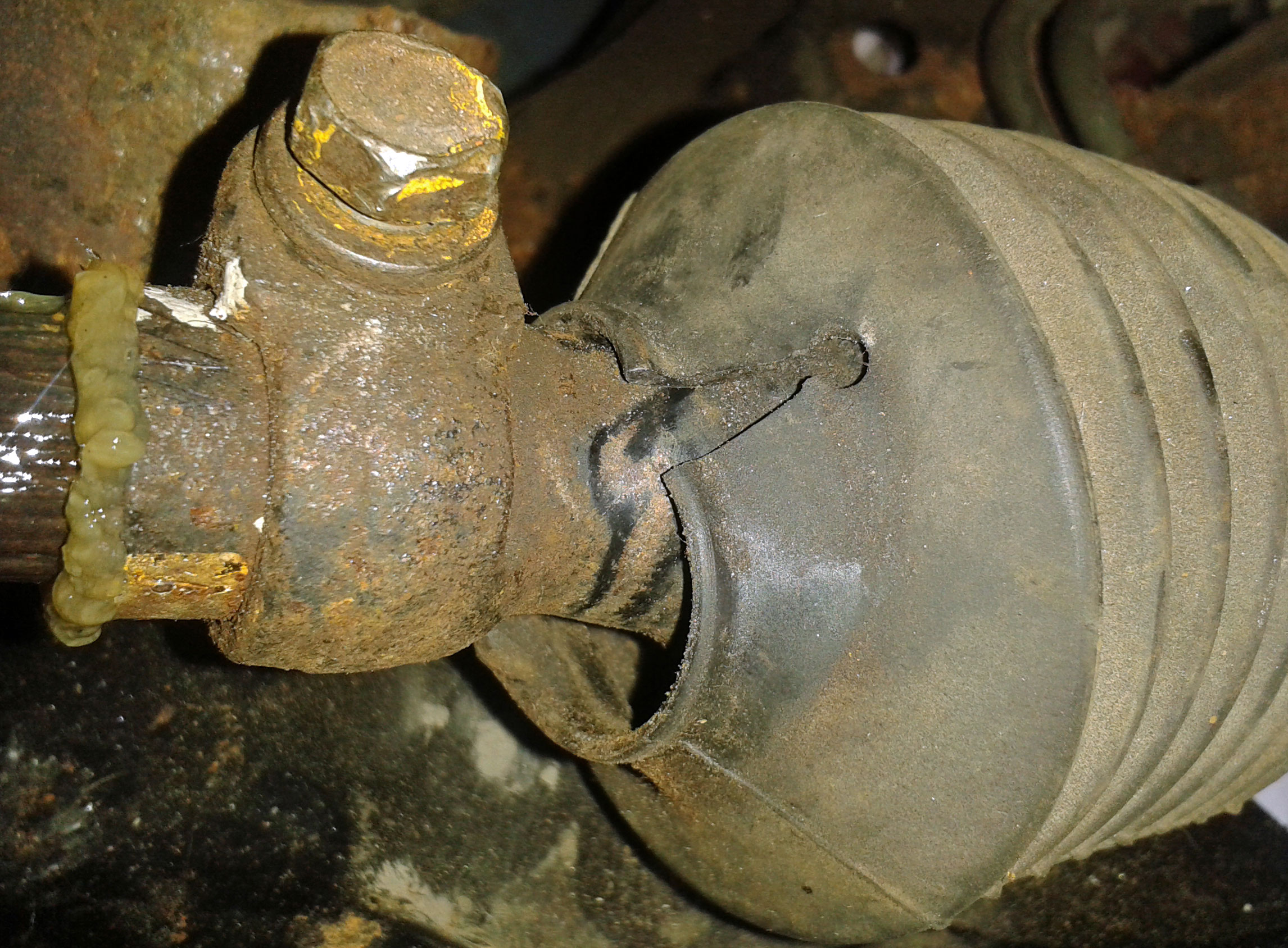 I've initially routed the throttle cable like this as it usefully used an existing plastic clip ... but I need to go find out how it was originally routed 'cos the cable feels a bit restricted in its movement... Again - you've never quite taken the photos of the donor that you need - just ones very near to them. 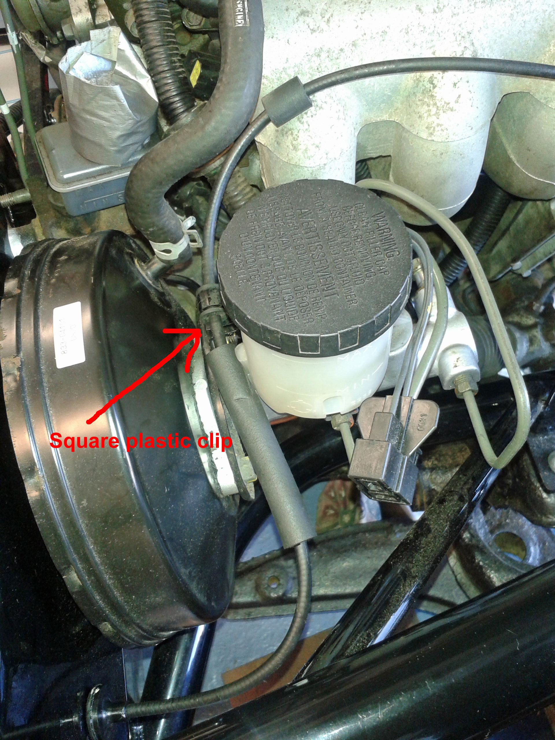 I also need to find out what people have done with the steering column plastic-shroud/metal/rubber pieces ... the rubber bit might keep some water out and the plastic shroud might protect the universal joint, but the mounting holes don't seem readily usable on the MEV-manufactured firewall whose metal turns away just there. 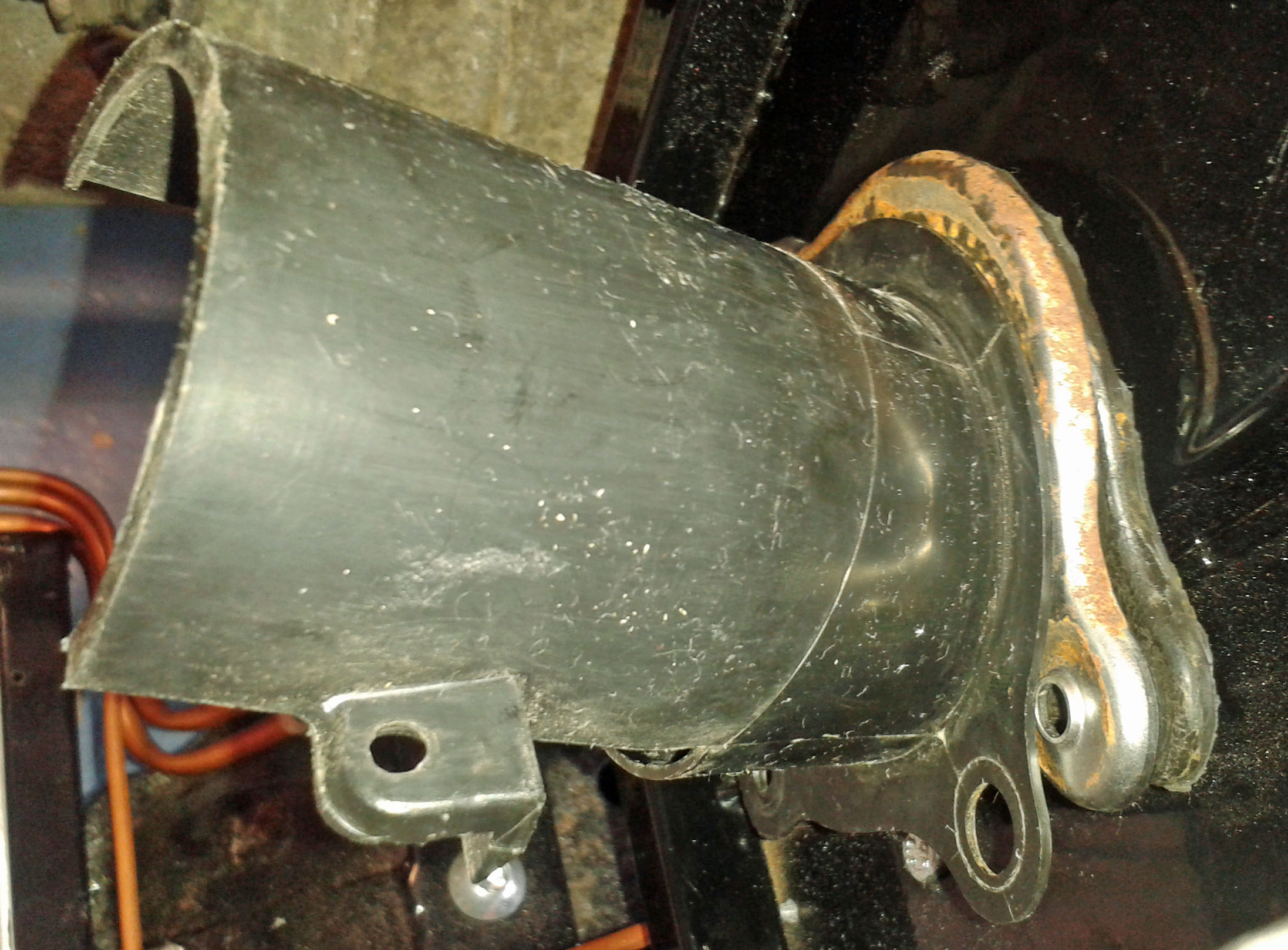 |
|
|
|
Post by jgilbert on Jul 15, 2015 22:17:41 GMT
Page 8 of my build for a write up on the steering column shroud fitment.
|
|
|
|
Post by lukiez on Jul 15, 2015 23:12:34 GMT
The general consensus is you don't need to cut the spacer tubes off the pedals, you can if you want to. You can bend the bottom steering brackets to meet the pedals.
Keyhole on the boot is normal, doesn't mean it has split - I looked into replacing it to find you had to buy the uj plus the new boot comes with the keyhole!
Throttle cable route looks about right, if its feels stiff check for frays on the cable or dirt/rust, even check the pedal itself isn't partly seized
|
|
|
|
Post by miket on Jul 16, 2015 11:49:35 GMT
Thanks for the info chaps - appreciated. Seems I've lost the smaller part of the 2-part plastic shroud - I vaguely recall there being 2 bits but there's only 1 now. I'm surprised to hear about bending the lower bracket - it seems way to thick for my sub-blacksmith skills/tools. I've now offered up the column without the pedals in place to see where the lower brackets land in terms of distance from the bulkhead. It seems the column is too long. I.e. with the two parts of the steering columns' splines fully engaged (and their clamp bolts in) the top of the column sits too far to the rear of the car to bolt up to the MEV-supplied mounting plate... 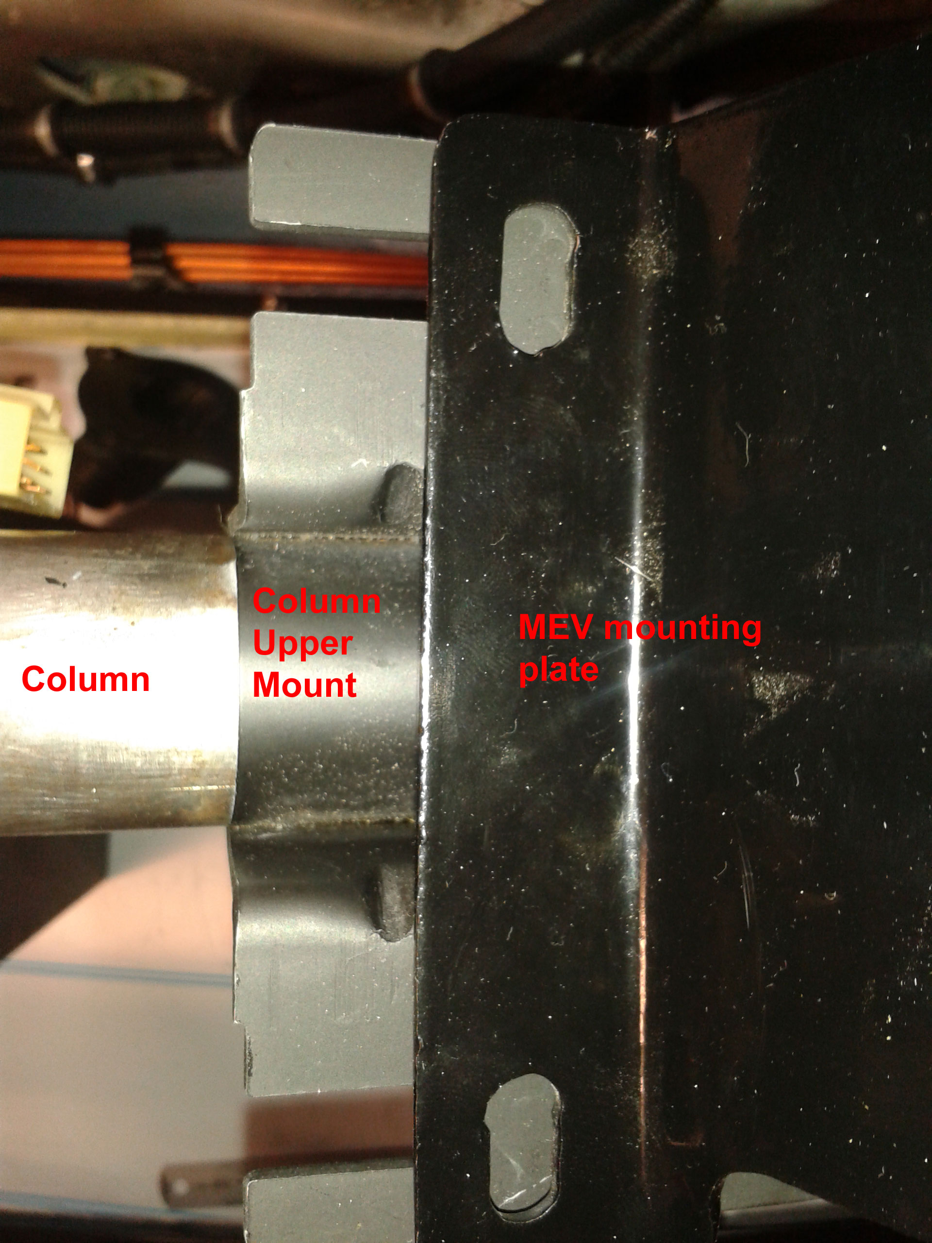 Similarly the lower brackets stand off the bulkhead by the same margin... 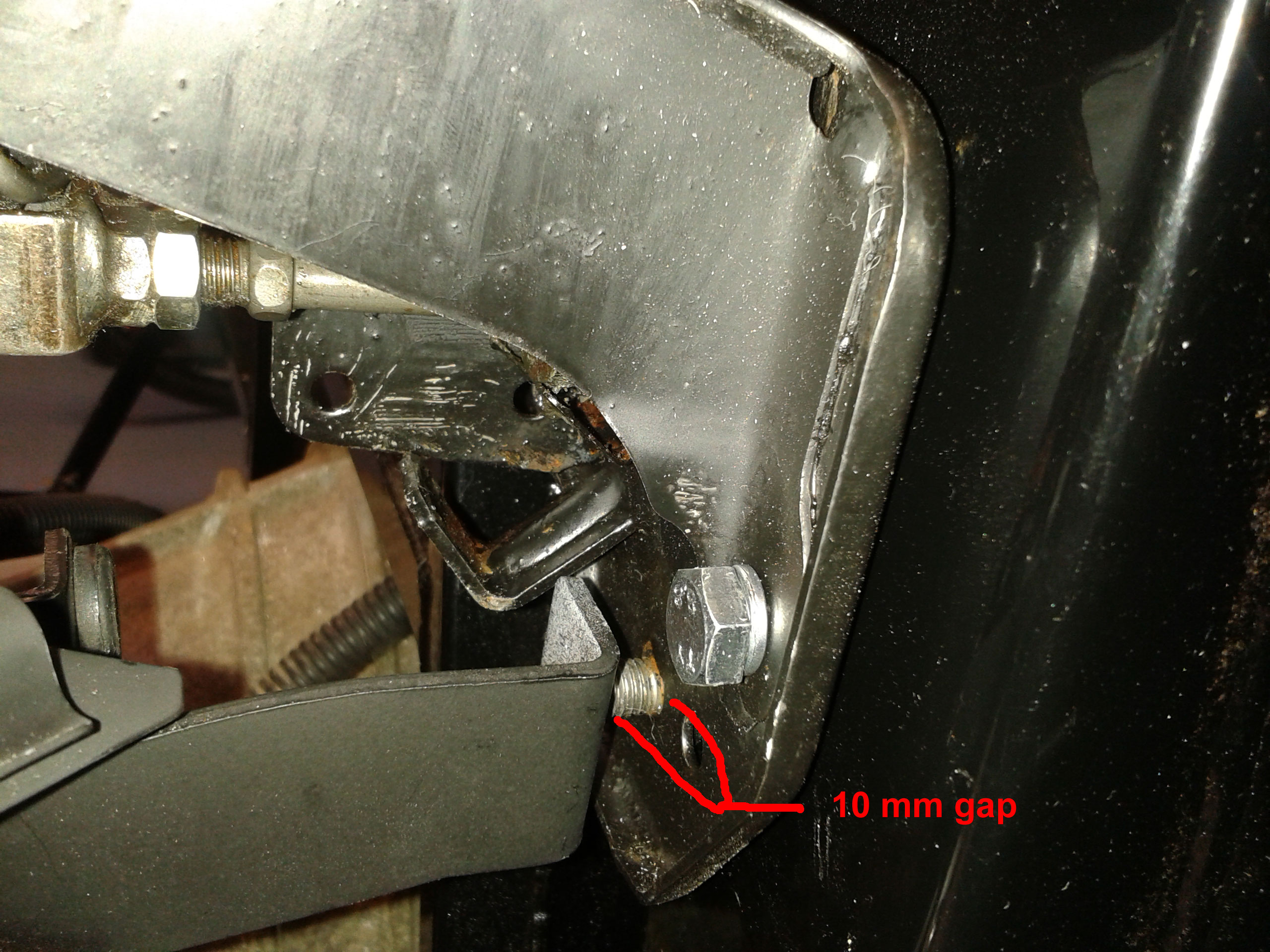 So even before I get to worrying about the spacers on the brake pedal assembly I have the issue of getting the column 10mm further forward in the car. Hopefully I'm missing something obvious and will see the light; otherwise it's extending the holes in the MEV-supplied plate ... or a controlled collapse of the column if the whole thing shortens!?? Not sure that's one of my better solutions tho'. |
|
|
|
Post by lukiez on Jul 16, 2015 19:43:06 GMT
I'd make the slot on the upper column mount as there's more metal there rather than the mev supplied plate, plus I needed to cut down the mount to make room for the speedo.
Despite the thickness of the metal, its surprising how pliable it is. It only needs bending if they are not the same angle as the fixing points on the pedals.
2 parts of the column slides, the inner shaft and the outer sleeve, light force and they should move keep an eye on the steering wheel end check the horn and indicators will still operate
|
|


