trident
Senior
 Improvise, Adapt and Overcome
Posts: 629
|
Post by trident on Jan 22, 2015 18:56:18 GMT
|
|
|
|
Post by miket on Jan 23, 2015 10:35:33 GMT
Good news - thanks; I've found and followed the flowchart and see what you mean.
I think I'll get the car up and running with the old exhaust (or at least most of it!) and then get something fabricated towards the end of the build when dimensions, spaces and shapes'll be clearer.
|
|
|
|
Post by miket on Jan 25, 2015 17:10:04 GMT
Another minor novice-milestone today - the chassis has been mated with the ppf. At last space in the garage to move around easier. In case it helps those who follow, here's some things to watch out for when marrying up the chassis & ppf:- 1. The two flat welded-on tabs at the rear end of the chassis frame (behind the floor - which I think allow for bolting to 1.8's rear subframe) are potentially lethal to any pre-fitted rear transverse brake line. Beware. 2. If you've fitted the old exhaust hanger on to the under-floor then it may well snag as it passes any conduit on the ppf. 3. The hangers on the exhaust itself will press up under the floor and may touch it (if like me you failed to find and address them beforehand).  4. The rearmost left (n/s) part of the front subframe (where the rearmost of the front n/s chassis/subframe fixing bolt goes) may overlap any floor-rivet that's right in the corner of the floor by the tranny tunnel. 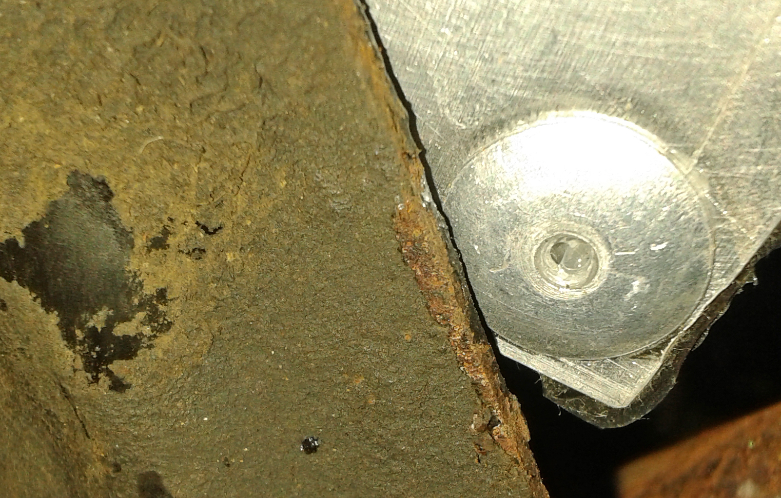 5. Similarly on the right (o/s) of the tranny tunnel the front subframe might overlap a floor rivet. I've assumed that this ensnared rivet head isn't a problem and that the fixing is still sound, but if anyone knows different it'd be good to know now rather than later (please). I also need to understand options on exhaust hangers, but I'll start a separate thread for that as I couldn't find anything elsewhere. |
|
|
|
Post by miket on Jan 27, 2015 18:11:06 GMT
Some progress on various fronts today:- Cut off the obstructive mid-pipe hanger rods from the exhaust, leaving a stub to weld new ones to if it becomes relevant when I get to finalising an exhaust system later in the build. Whilst under there noticed that the rearmost of the front subframe bolts extends enough to encourage speed-bump problems:-  Bent the proportioner valve bracket further to keep it from being too friendly with the manifold when the engine (eventually) vibrates. Adjusted my brake and fuel lines where they turned 90 degree corners at the front end - the excess weld on the box section was too close to the lines and now there's a more obvious gap to avoid abrasion risk. Offered up the Mk1 tank again for fitting the Exo-guide way round. Looks like 54mm of spacers will give a 6mm clearance between drain plug (which will become inaccessible) and subframe. Cut, flared and fitted front/rear brake line to the rear splitter - the Serenco Powerhand flaring tool worked well for making a good flare in situ. |
|
|
|
Post by mawdo81 on Jan 28, 2015 10:11:56 GMT
Can you switch that bolt round so the head is under the car (with a lower profile) but the nut and rest of the protruding bolt is out of harms way?
|
|
|
|
Post by miket on Jan 28, 2015 18:05:14 GMT
Thanks, yes that's an option - tho' that'd put the nut/excess in the footwell instead. I think I'll wait until I decide how I fasten the seats in and then be consistent. For the seats it'll feel more 'failsafe' having the bolts put in downwards and the nuts underneath, but then there'll be the same issue of the chunky nut waiting to meet speed bumps. One for later I think. Today I put the fuel tank on hold while I decide what to do for the best. I'm concerned that 54mm spacers that are just tubes will not be very resistant to lateral force if there was an accident - tho' this isn't based on any engineering knowledge. So I'm thinking of mounting some square section side/side on the frame's brackets and then more square section front/back at whatever angle fits the tank. This might then allow for more flexibility with the tank positioning, including turning it round. I think I've seen a thread where this was done. Extra weight but not a worry for me. So I decided to start on the bulkhead and tranny tunnel. I tried to start with the L (n/s) bulkhead, but found I wasn't sure what area it needed to cover. I thought it only needed to come out to meet the side panels, but didn't know whether to go out further than that higher up and didn't know how far out I could go before losing contact with the tranny tunnel. So I bit-the-bullet, got the power tools out and made the gear lever hole. Went okay so I was able to do a bit of trimming to get it to sit more-or-less in place. The lip on the bottom edge hadn't been turned enough to sit flat so I bent that a bit more. I tried doing the full length in a Workmate, but we weren't up to it so had to use the vice and do a bit at a time - not harmed it. The tranny doesn't sit just right tho' - the bend on the L (n/s) side of the tranny isn't bent enough so there's a gap:-  I think rather than try to bend it off the car; I'll fasten the Right (o/s) side to the frame snug against the permanent tunnel, then fasten the rear of the L (n/s) side snug against the permanent tunnel and then push/pull the front L (n/s) to best fit and fix it down. Well that's the best plan I have so far. Couple of Q's arising if anyone's read this far;- Do people butt joint these panels or bend 'tongues' around at the joins? With butt joins it feels there'll always be some sort of gap - if it matters. When people use rivnuts, which have a raised lip, what do they put in between the panel and frame to fill the gap that must run between each rivnut? |
|
|
|
Post by mawdo81 on Jan 28, 2015 19:22:00 GMT
I'll be going for all nut heads under the car to minimise the risk of catching on a sleeping policeman...
|
|
|
|
Post by jgilbert on Jan 28, 2015 21:50:09 GMT
Thanks, yes that's an option - tho' that'd put the nut/excess in the footwell instead. I think I'll wait until I decide how I fasten the seats in and then be consistent. For the seats it'll feel more 'failsafe' having the bolts put in downwards and the nuts underneath, but then there'll be the same issue of the chunky nut waiting to meet speed bumps. One for later I think. Today I put the fuel tank on hold while I decide what to do for the best. I'm concerned that 54mm spacers that are just tubes will not be very resistant to lateral force if there was an accident - tho' this isn't based on any engineering knowledge. So I'm thinking of mounting some square section side/side on the frame's brackets and then more square section front/back at whatever angle fits the tank. This might then allow for more flexibility with the tank positioning, including turning it round. I think I've seen a thread where this was done. Extra weight but not a worry for me. So I decided to start on the bulkhead and tranny tunnel. I tried to start with the L (n/s) bulkhead, but found I wasn't sure what area it needed to cover. I thought it only needed to come out to meet the side panels, but didn't know whether to go out further than that higher up and didn't know how far out I could go before losing contact with the tranny tunnel. So I bit-the-bullet, got the power tools out and made the gear lever hole. Went okay so I was able to do a bit of trimming to get it to sit more-or-less in place. The lip on the bottom edge hadn't been turned enough to sit flat so I bent that a bit more. I tried doing the full length in a Workmate, but we weren't up to it so had to use the vice and do a bit at a time - not harmed it. The tranny doesn't sit just right tho' - the bend on the L (n/s) side of the tranny isn't bent enough so there's a gap:-  I think rather than try to bend it off the car; I'll fasten the Right (o/s) side to the frame snug against the permanent tunnel, then fasten the rear of the L (n/s) side snug against the permanent tunnel and then push/pull the front L (n/s) to best fit and fix it down. Well that's the best plan I have so far. Couple of Q's arising if anyone's read this far;- Do people butt joint these panels or bend 'tongues' around at the joins? With butt joins it feels there'll always be some sort of gap - if it matters. When people use rivnuts, which have a raised lip, what do they put in between the panel and frame to fill the gap that must run between each rivnut? Yorkie, Trans cover to chassis fit is a difficult job to get right. My number one tip would be to make sure that the trans cover always goes back in the same place when you trial fit it. Either mark it with lines and arrows or use a locating screw/bolt. I ended up welding an extra 10/15 mm plate onto the side of my chassis for the trans to sit nicely on. Another option is a trip to B&Q (hardware section) and buy some 10mm x 10mm light gauge Ali angle that you could bend to suit and pop rivet to the side of trans cover (spray it black or your frame colour for a nice contrast). This would get around the gap problem. Buy some thin rubber sheet (I use 1mm) off ebay, double sided sticky tape and stick a strip to the bottom of the trans cover with holes where your rivenuts are. Hope this helps. Good luck. |
|
|
|
Post by miket on Jan 29, 2015 17:52:30 GMT
Yes, thanks - useful ideas/info - additions to long shopping list.
Today I started on the driver foot bulkhead, but decided to wait until I'd fixed the tranny based on jgilbert's advice.
Also realised that the bit of flooring ally I have left won't be enough to make the upper centre bulkhead out of - despite me doing what I thought was the most efficient cut of the floors. So for anyone following; try to cut the floors in a way that leaves you a piece about 50mm by 40mm.
Went on to mark up the tank cover ready for cutting the gaps for the towers. One of those tricky jobs where you're measuring from a place it won't be when it's in its final place ... just need to read up on cutting fibreglass next as no doubt there's some keys to success.
Thought it'd be worth getting the tank cover to seat so I can make sure my tank won't foul before I fix it in place.
|
|
|
|
Post by jgilbert on Jan 29, 2015 21:50:37 GMT
Yes, thanks - useful ideas/info - additions to long shopping list. Today I started on the driver foot bulkhead, but decided to wait until I'd fixed the tranny based on jgilbert's advice. Also realised that the bit of flooring ally I have left won't be enough to make the upper centre bulkhead out of - despite me doing what I thought was the most efficient cut of the floors. So for anyone following; try to cut the floors in a way that leaves you a piece about 50mm by 40mm. Went on to mark up the tank cover ready for cutting the gaps for the towers. One of those tricky jobs where you're measuring from a place it won't be when it's in its final place ... just need to read up on cutting fibreglass next as no doubt there's some keys to success. Thought it'd be worth getting the tank cover to seat so I can make sure my tank won't foul before I fix it in place. Cutting F/G. Fibre glass is a very soft material so you should take your time when cutting. Stick masking tape on the surface to minimise the gel coat chipping. This also helps centre a drill if drilling. Drill a hole in the internal corners so that you get a nice radius. Invest in a dremel type tool with some thin cutting discs and small drum sanding wheels. A B&Q version will do. The dremel and thin disc will cut with easy and accurately. Measure twice and cut inside (waste side of line) and sand to finish. Wear eye protect and a face mask! Just take your time and enjoy. If you don't want to spend money on a dremel then a jigsaw or even hand saw will work however, a dremel is a hundred times better. |
|
|
|
Post by miket on Jan 30, 2015 20:50:27 GMT
That's great info, thanks. I guess the internal-corner-drilling reduces the chances of cracking/splitting. I have a dremel clone from one of Aldi/Lidl's 'specials' and it has indeed been useful. I saw that a mask for F/G should be a pretty damn good one - I'll have to trade off health vs cost (again)  No progress for a few days now - time for a break in the snowy Lakes. |
|
|
|
Post by miket on Mar 19, 2015 23:16:24 GMT
... so best part of 2 months flies by. Came home to broken boiler, had to move stuff out of way of boiler which took 2 weeks to replace, whilst shelves out of way a good time to put in more power sockets...etc etc - you know how one thing leads to another. Anyway, back to the car today and resumed installing the fuel tank and its cover.
As noted elsewhere the brackets ready-fitted by MEV to the chassis don't allow many options for fitting a Mk1/1.6 tank the MEV-intended way round and they force installation to the R (o/s) and forward. I moved it as far L as possible whilst not drilling too close to the edges of the brackets and the tank cover fits over it okay. But.. my copper fuel pipes emerge vertically behind the rear bulkhead and I don't have enough room to run the flexible hose between the front edge of the tank and the inside of the front face of the cover - so I'll have to bend the copper pipes to point the hoses off round the side or cut some of the spare edge off the tank. Anyone else hit this one?
Also, my 54mm spacers lift the tank as high in to the cover as the cover will allow - a tight fit that I think should be okay depending on what I do with the charcoal-canister-pipe fitting on the tank. More reading to do on this.
I made the necessary cut-outs in the tank cover. They've ended up bigger than necessary but not a disaster. I 'measured twice' etc and cut them the size I'd intended okay, but the various complex curves of the cover and the sloping suspension mount meant it could have been better sized and shaped if I'd been better able to think in 3D.
Good to be back.
|
|
|
|
Post by jgilbert on Mar 19, 2015 23:43:19 GMT
Missed your updates. Yes difficult job to cut the rear cover. Point to note for MEV maybe.
Weather is getting better, big last push to a summer drive.
|
|
|
|
Post by Toed64 on Mar 20, 2015 0:19:22 GMT
... But.. my copper fuel pipes emerge vertically behind the rear bulkhead and I don't have enough room to run the flexible hose between the front edge of the tank and the inside of the front face of the cover - so I'll have to bend the copper pipes to point the hoses off round the side or cut some of the spare edge off the tank. Anyone else hit this one? Yes, I gripped the front lip of the tank with a mole wrench and bent about a 10cm wide section of it up, just enough to allow the petrol pipes to continue vertically. Easy and no problem at all. |
|
|
|
Post by miket on Mar 21, 2015 10:16:05 GMT
Thanks guys ... yes of course - bending's a better idea if I can avoid disturbing the seam - did you make a cut in from the edge at either end and bend the 'flap' or just bend without cutting?
I'll see if I can quickly mock up what a close fitting fuel-tank-cover rear-suspension-cut-out would look like in case it helps others down the line.
|
|


