|
|
Post by jgilbert on Sept 30, 2014 22:29:35 GMT
Trident very interesting.
So my understanding (from googling the same issue) is;
Standard MX5 flasher units would have been designed to cope with the Electrical Load (current) draw by the existing bulb set up.
1 Front 21watt
1 Side 5 watt
1 Rear 21 watt
This is show on the flasher body on your photo 21w x2 +5w + 1.4w (guess the 1.4w is the flasher load).
So the flasher is expected to see a load of 48watts from the bulbs.
With LED's you significantly reduce the load, say 9watts. So you have to install an additional load of 21w-9w = 12w.
Watts = Volts X Amps ..so 12W / 12V = 1A
To Figure the resistance you need to pass 1A at 12V you use Ohm's Law
V = IR
12 = 1R
so you would need a Resistance = 12ohms.
I have found these.
Arcol HS25 Series Aluminium Housed Axial wire-wound Panel Mount Resistor, 12 Ω ±5 % 25 W
Price £1.84
From RS Components
You seem to have found an alternative nice solution. It would be good to understand how this works from another member more clued up than me.
|
|
trident
Senior
   Improvise, Adapt and Overcome
Posts: 629
|
Post by trident on Oct 1, 2014 17:20:45 GMT
Trident very interesting. So my understanding (from googling the same issue) is; Standard MX5 flasher units would have been designed to cope with the Electrical Load (current) draw by the existing bulb set up. 1 Front 21watt 1 Side 5 watt 1 Rear 21 watt This is show on the flasher body on your photo 21w x2 +5w + 1.4w (guess the 1.4w is the flasher load). So the flasher is expected to see a load of 48watts from the bulbs. With LED's you significantly reduce the load, say 9watts. So you have to install an additional load of 21w-9w = 12w. Watts = Volts X Amps ..so 12W / 12V = 1A To Figure the resistance you need to pass 1A at 12V you use Ohm's Law V = IR 12 = 1R so you would need a Resistance = 12ohms. I have found these. Arcol HS25 Series Aluminium Housed Axial wire-wound Panel Mount Resistor, 12 Ω ±5 % 25 W Price £1.84 From RS Components You seem to have found an alternative nice solution. It would be good to understand how this works from another member more clued up than me. John, I'm not going to pretend to understand any of it, because I don't. I just followed the info on the blog from this link forum.miata.net/vb/showthread.php?t=335534The original post was put up quite a few years ago so it appears to be an OK long term solution which costs next to nothing and is a very easy and neat fix. |
|
|
|
Post by mawdo81 on Oct 1, 2014 17:31:09 GMT
It's not 12v though, as that would effectively ground the other side of the resistor, in those equations it is the voltage drop that is used.
|
|
trident
Senior
   Improvise, Adapt and Overcome
Posts: 629
|
Post by trident on Oct 8, 2014 15:46:12 GMT
Quick question time…. I have no brake fluid in the master cylinder… when I turn on the ignition without the hand brake on i was expecting to see the brake warning light to indicate that i have no fluid how ever i have no warning light to indicate the fact I don't have brake fluid. the light works with the handbrake.
I assume it should be the same light that acts as a warning or am I wrong.
Cheers Chris
|
|
|
|
Post by nitram on Oct 8, 2014 16:19:08 GMT
|
|
|
|
Post by biggunz on Oct 8, 2014 17:09:00 GMT
Am I right in thinking it's just a float switch? If the light is working with handbrake does it rule out electrical issues possibly ia mechanical problem with the switch? Possibly the float is stuck?
Shaun
|
|
|
|
Post by gwnwar on Oct 8, 2014 17:39:44 GMT
Is the wire hooked up to the master cly. Was the wire or part of it cut when taking out extra wires..
|
|
|
|
Post by jgilbert on Oct 8, 2014 18:07:37 GMT
Two black wires from side of reservoir go to a large ish black connector. Black and white wire run from the connector into the loom.
|
|
trident
Senior
   Improvise, Adapt and Overcome
Posts: 629
|
Post by trident on Oct 8, 2014 19:19:13 GMT
Everyone thanks for your advice ….. just spent the past hour in the garage and the issue is now sorted along with the issue I had with the full beam on my headlights when the engine is running. Mind you I'll have to check the headlights tomorrow otherwise I'll wake my neighbours baby with the roar of the engine without an exhaust.. must sort that. Anyway I checked the float switch using the handbrake wire and a direct earth to the chassis.. it worked… at least i didn't have to spend out money on a new switch.. after tracing the earth wire back it turned out to be an issue with one of the earth blocks. Every connector was very corroded so I took it apart and gave it a dame good clean and put it back together and as if by magic the warning light on the dash worked and when I raised the float in the master cylinder the light went out. JOB DONE. 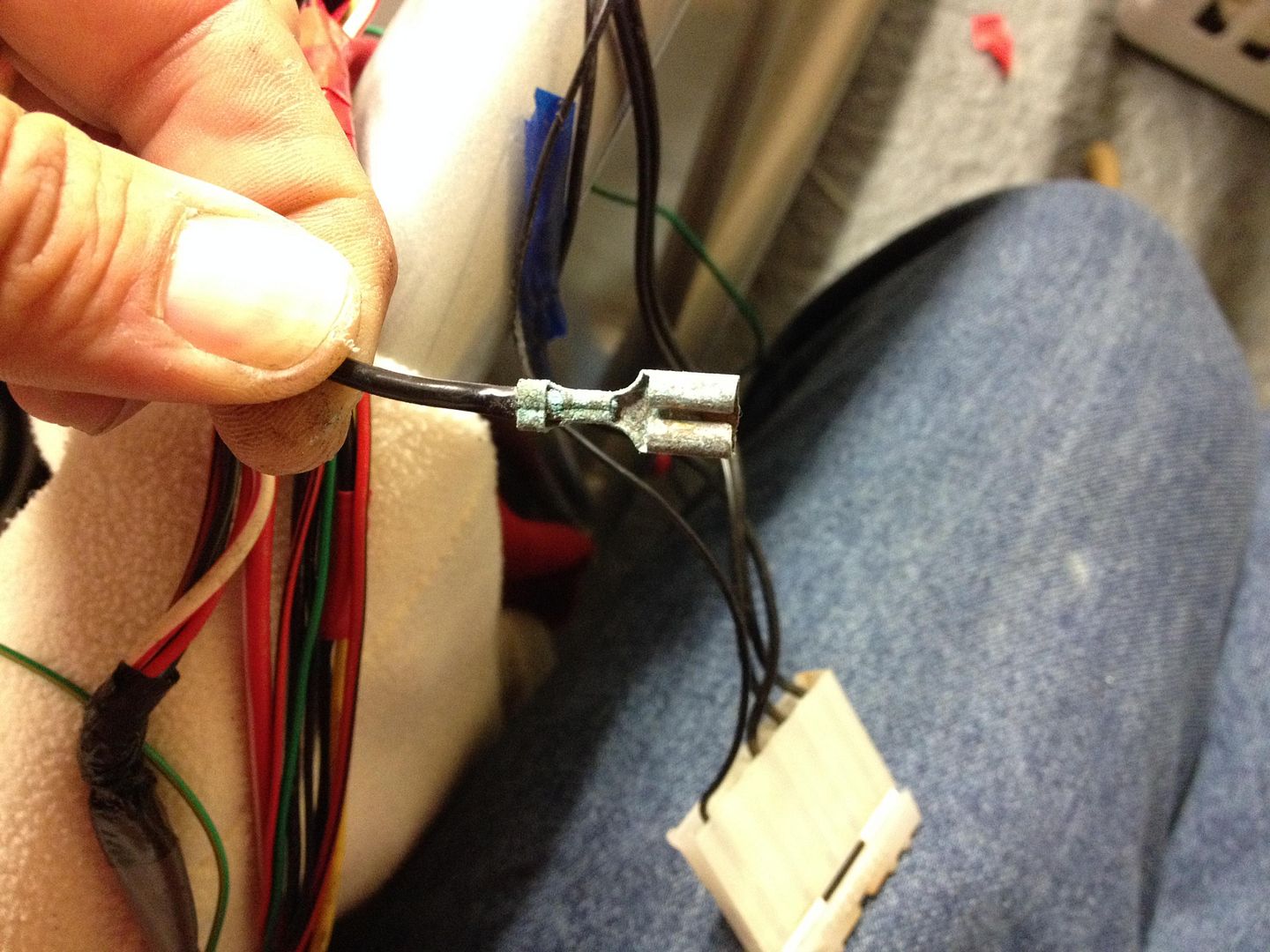 |
|
trident
Senior
   Improvise, Adapt and Overcome
Posts: 629
|
Post by trident on Oct 9, 2014 15:41:31 GMT
Starting to hate electrics…. everything is now working …. that is until I start the engine.. The issue I have is with the full beam on the headlights. Engine off everything works as it should…. start the car and flash full beam lights work fine .. put on dip beam and flash headlights full beam comes on and stays on … it will not drop back to dip beam .. same issue when you push the lever forward for full beam …. they stay on even when you pull the lever back to take off the full beam. Why will it work ok without the engine running and then not work with the engine running? I could understand it if they didn't work at all but this has got me scratching my head as it can't be an earth problem as the lights work ok when the engine is off. My headlights are the photon headlights from RTR and the full beam works on a relay that operates a flap inside the unit to expose the full light pattern on full beam. It's almost as if with the engine running it is giving the relay too much power and it won't disengage when the lights are turned back to dip from full beam. If any one has any ideas?  ?? |
|
|
|
Post by jgilbert on Oct 9, 2014 16:42:38 GMT
Are you able to sketch a wiring diagram of how you have wired the photon headlights up? Might help solving the problem.
|
|
trident
Senior
   Improvise, Adapt and Overcome
Posts: 629
|
Post by trident on Oct 9, 2014 19:02:47 GMT
Are you able to sketch a wiring diagram of how you have wired the photon headlights up? Might help solving the problem. It's wired up using the three wires that went to the original headlight bulb to the three wire on the light unit. I've played around with trial and error and the way I have it wired is the only way that everything works correctly….. except when the engine is running. CAR LIGHT UNIT THICK RED / WHITE - WHITE / BLUE RED / BLACK - WHITE / RED BLACK - BLACK / YELLOW The main engine earth strap looks quite corroded so will replace this and see what happens + have another look at the earth connections that I cleaned up the other day… may be just replace the block connector and add some new ground points using a few rivnuts. |
|
|
|
Post by jgilbert on Oct 9, 2014 20:00:27 GMT
I've used this in all my connectors. Available via internet.  |
|
|
|
Post by gwnwar on Oct 10, 2014 5:10:33 GMT
Car harness R/W are power to high beam.. R/B power to low beam.. Black ground.. both head lamps and combo switch ground at the main ground point.. Check the black wires to both head lights and to the combo switch are good to ground. use OHM meter looking for 0.00 reading.. check fuses for head lamps.. Take your lamp units apart to see were wires go inside..
|
|
trident
Senior
   Improvise, Adapt and Overcome
Posts: 629
|
Post by trident on Oct 16, 2014 18:15:48 GMT
Little bit of an update Hopefully I have sorted out all the electrics part from fixing them in for the last time. I do take my hat off to those of you that have fitted your loom in without cutting any unused wires out. Even with load of wires removed its still a pain in the rear. I have had to extend some wires and shorten others but i'm pretty much there. I had to build a small tray to fit my ECU and the engine immobiliser which I have decided to keep as it add an extra level of security. The tray was made out of some perforated steel that i had lying around. Just the right amount.. The red tape is there to protect my chassis for the time being but I will get the tray powder coated in a few weeks along with a few other brackets that need doing. 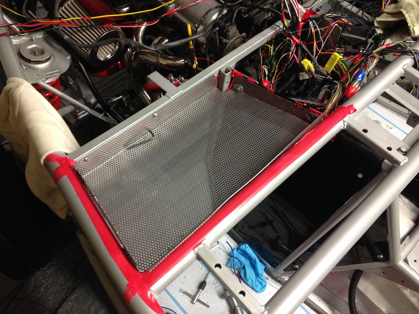 ECU and immobiliser fitted with main bulk of wires in the centre console area. I will be adding a aluminium sheet across the whole width of the car covering the tray centre console and pedal area to protect the electric and prevent any water getting to them. 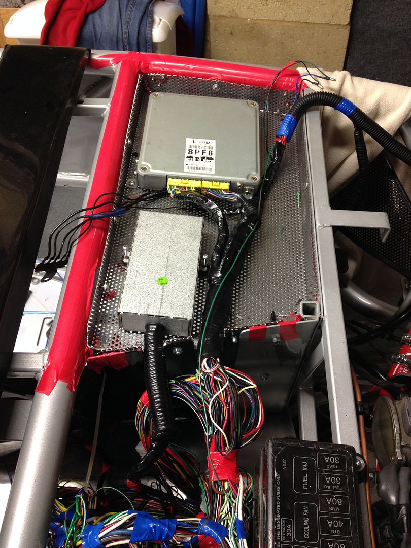 I've also fitted a flexi clutch line that I got from "the freak". Had to adjust the bracket angle very slightly at the rear of the engine but all good now. Filled the master cylinder with fluid and I now have a working clutch. Brakes were also done but I had an issue with one of the recon calipers in that fluid would leak from the bleed nipple even when it was full done up. Upon inspection it appeared that there was an issue with the thread insert. Bearing in mined I purchased the callipers over a year ago ( August 2013 ) I didn't hold out much hope in getting it replaced ………. however I explained to the company that I was building a kit car and this was the first time I had tried to bleed the brakes and they were superb… Sending out a replacement calliper in the post so will have to re do the brakes when the replacement arrives. Very good customer service.. www.carfactorsuk.co.uk 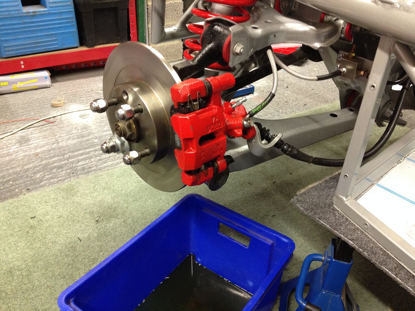 Also filled the rad with coolant and ran the engine to get it up to temperature..very noisy with no rear exhaust but she ticked over lovely with no leaks and fan cut in and it stayed at a very nice temperature on the dash, just under half way. If it hadn't have been for the brakes I would have been able to drive it out of the garage for the first time …. oh well I'll just have to wait. |
|