|
|
Post by adam1001 on Feb 7, 2014 1:03:26 GMT
So, a bit more from 2013.
First off, the fuel tank. Decided to spin it round 180 degrees as I think this setup is a lot more elegant. Just meant trimming back the rear mount on the chassis so it'd fit. Paul was helping me with this and all was going well. Then we had a stroke of genius: there's a flat section of the fuel tank which sits right over the rear mount. Flat, as it's part of the seam. Drilling a hole through this would mean not having to weld in an extra mount, a much better option as the chassis is already coated. So Paul drilled the hole. The smell of petrol was a worry. Turns out that although the tank is flat on top we hadn't thought to look underneath, where it leaves the join closer to the edge. We weren't far off the seam, but just far off enough to have gone through the tank. Aaaaggghhhh. Three options: new tank, weld it up or use some sort of grommets sandwiched between the mounting bolts. The third option seemed the easiest, but in the end we decided it wasn't the best as it wouldn't guarantee a sealed tank. So I drained the tank and took it to the local welder who rinsed it with water and did a great job. All sorted, but unless you're confident welding the tank I wouldn't recommend it.
The next saga was the cambelt: difficult for all the wrong reasons. I bought a locking tool from Autolink but it turns out my pulley has a deep dish on it so the locking tool was useless. In the end I used the air gun which got the main nut undone and the four round the edge weren't so hard. As I had the cam cover off anyway I decided to get it bead blasted. The result wasn't perfect but a lot better than how it started. The only really annoying thing was that the beads get everywhere, inside all the chambers, you name it. So I had to open it all up, give it a major clean and rinse and then re-stick all the chambers again. The belt itself was incredibly easy. Just the five crank pulley bolts to tighten once I've got the brakes up and running.
Final one was the roll hoop. I had a very early detachable one which I found out from the forum needed modifying. I gave it back to Stuart ages ago and never got round to collecting it. Eventually I asked him to send it which he kindly did. But after modifying there was no way it was going to fit, the distance between the front and rear mounts was a good 15-20mm too short. I messaged Stuart and he told me to give it a good pull which I very much doubted - it was way too far out. That evening I was talking it over with a friend and tried giving it a massive pull. Unbelievably it all slotted into place. And even better it completely covered the hole I'd cut by mistake in the rear bulkhead panel. Another job ticked off.
|
|
|
|
Post by adam1001 on Feb 7, 2014 1:23:09 GMT
Here are some pictures from 2013. 2014 update in the next few days... things are progressing.  First attempt at front brake pipe brackets. Looked good, but just not quite enough reach on full lock. Back to the drawing board.  Rivnut mounted in rear fuel tank bracket (trimmed for backwards tank mounting). What could go wrong?  Welded fuel tank - as good as new, now with added petrol-tight hole.  The old steel bracer bar. Made £26 on Ebay.  Cusco lightweight aluminium front bracer bar - came with the red MX-5 I bought for the shocks. Now sprayed black and mounted (goes further forward than the original).  Cam cover pre-blasting  Changing the cambelt  The crank pulley which is incompatible with all removal tools  Cam cover post-blasting. Not perfect but definitely better.  The JR cold air intake aluminium pipe. Which doesn't fit in the Exocet. Had to buy an original air inlet pipe.  The gearstick makes an appearance.  Paul lining up the bonnet and nosecone.  Aligning the nosecone.  Not mine (I wish). Ben came over to have a look at my progress and let me drive an Exocet for the first time. Wow! gave me a lot of inspiration and felt amazing. A seriously well built kit.  Fibreglassing the seat supports onto the seats.  My mother helping me cut the seat padding. Clearly Halloween.  The finished padding. I think it looks good, but it's pretty thin for comfort purposes. We'll have to see...  Revised front brake pipe brackets  The end of 2013. |
|
|
|
Post by gwnwar on Feb 7, 2014 7:01:23 GMT
Adam.. With the timing belt did you follow a write up of how to.. and use a new key and bolt and torque to revised torque spec. did you do the rotating of the crank to set the tension on the belt for the tensioner preload setting..Did you have the right number of belt teeth between the marks on tops of the cam gears..Intake cam will slip if not secured..
|
|
|
|
Post by adam1001 on Feb 7, 2014 11:30:19 GMT
Hi Gwnwar, thanks for the comments on the cambelt. All good and all done: I followed the writeup here. The pulleys had been marked previously and I checked the marks after a few turns when I'd finished and they lined up perfectly. I did the crank oil seal as well (I left the camshaft ones as they looked fine). The only step I haven't done yet is torqueing the crank pulley as I haven't quite finished the brakes and will need them to lock the engine. Is it necessary to use a new bolt and pin? (I'm guessing you'll say yes!) They don't come with the cambelt kit so I didn't bother. Very easy to do at this stage anyway as it's only finger-tight. What are the revised torques out of interest? |
|
|
|
Post by bauer on Feb 8, 2014 3:40:16 GMT
always better to replace the key and bolt if you can
That said, it looks like you have a long nose crank engine so the risk of failure down the track from not changing the key is minimised. If you had a short nose crank engine, I would recommend you go back and change it.
great build thread btw, enjoying it.
Stu
|
|
|
|
Post by gwnwar on Feb 8, 2014 6:08:08 GMT
I have gone with and without replacing.A lot depends on condition of key and keyway and if it has been apart before and bolt torqued a couple of times..your call.. Not a big thing but in your write up the key is being called a Woodruff key.. It is not.. a woodruff is round on the bottom (1/2 moon) There were good pic in your writeup.. Have you seen this on Miata.net on belt replacements and other good info on the site.. www.miata.net/garage/garagemaintenance.html |
|
|
|
Post by adam1001 on Apr 7, 2014 14:35:08 GMT
Jumping forward in time a little I'm making great progress and even got the engine running this weekend: fired up first go (well, after a lot of cranking) which was very pleasing. Hoping for completion in late April/early May... biggest jobs left are electrics tray, slimming down and re-wrapping the wiring loom and mounting all the lights. The fuel filler flap is a work of art, I'll put up some pics and a description when I have a spare moment.
|
|
|
|
Post by adam1001 on Jun 19, 2014 10:46:13 GMT
Well... it's been a journey. Took about two years longer than I was expecting but this morning the car is in a fit state to drive on the road for the first time. I still have to do all the IVA bits (edge trim, bolt covers etc.) but it's now MOTable. I'm really pleased with the standard of build, it's probably cost me a fair bit more than the average but it looks good if I don't say so myself.
I'll try and do some updates over the next few days: things like the fuel filler flap, wiring, Acewell dash (which was a nightmare to fit) and exhaust might be of interest.
I'll stick some photos up when I can. At the moment the road outside my house is being fully excavated and resurfaced so I can't really do much.
|
|
|
|
Post by adam1001 on Jun 23, 2014 21:19:38 GMT
So on the 19th June (my Birthday incidentally) the Exo had its maiden voyage, up and down the newly resurfaced road, just as it half opened so I had it to myself. Unfortunately they then decided to close it again (they said the surface wasn't dry enough but I think they wanted to stop me caning up and down it) so we got stranded at the wrong end on the wrong plates. Gave me a chance to take a few pictures and fortunately the road re-opened a few minutes later so we swiftly retreated to my garage. First impressions: really impressed. All running well, suspension not nearly as harsh as I'd imagined it would be and the exhaust sounds lovely. Today I went for a cheeky MOT to give the car one final test before the IVA (no date yet). I got it up to 70 on the way there and apart from major crying issues from the wind it was awesome. Tracking is out, brakes were way too hard and the suspension needs a little tweaking, otherwise superb. The top-end death-rattle finally went away, I guess as it's the first time I've got it up to temperature with new oil in (Mobil 1 fully synthetic 0W40). The MOT guy was fantastic, and even got in someone from the next unit who used to work for VOSA. He picked up on one copper brake pipe which needs mounting better, brake servo inactive, and headlamp aim out. Other than that it would have been a pass: emissions and brakes both well within limits. Of course I have a list of jobs I still need to do for the IVA (edge trim, tethering the fuel cap, fitting the manufacturer's plate etc.) but it's great to know it's roadworthy. Oh, and the brake servo was the pipe connected back to front. Quickest fix ever. Here's a few pictures:    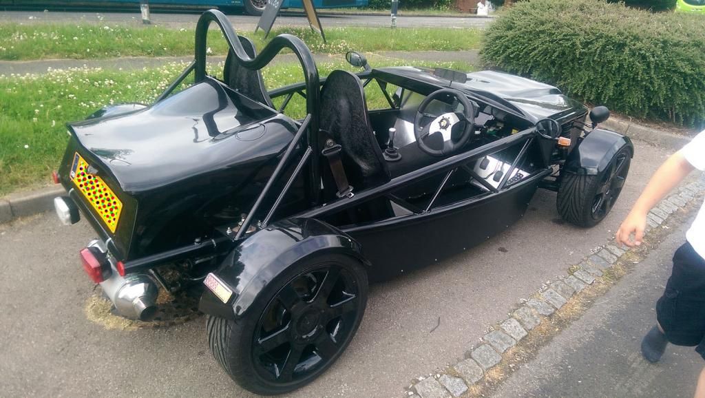  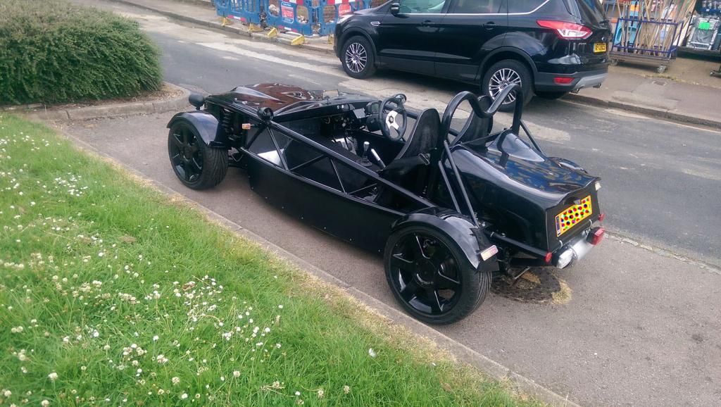 |
|
|
|
Post by adam1001 on Jun 23, 2014 21:38:24 GMT
The exhaust
When I got the car it had a sort of Mk1/Mk2 mash-up on it. Downpipe was Mk1, then it had a cat replacement pipe (with silencing) and the rest was Mk2. I've replaced the manifold and downpipe with a stainless Jasma 4 into 1 (my first attempt was a new one from tuningpartsbay on eBay which was rubbish and didn't even fit), kept the cat replacement, then fitted a Mk1 section to the back. The rear silencer is way too big for the Exocet so I've cut it off and replaced it with a badboy back box which I bought on Ebay for £3.20 plus postage. The end result is really good.
|
|
|
|
Post by adam1001 on Jun 23, 2014 21:38:54 GMT
The dashboard
I decided to go for an Acewell 7659 dashboard. It's a lot more elegant than the original and takes up far less space. However I probably wouldn't have gone with it if I'd known the problems it would cause. I didn't have one single problem with any of the electrics, however the dash was a major headache. If anyone's thinking of doing a similar set-up this will save you hours.
Issues:
Firstly the water temperature sender is calibrated completely differently from the MX-5 one. The dash was provided with a sender, however fitting a second one wasn't the most elegant solution (the original one is still required for the ECU) but in the end it was the only option. Fortunately the perfect place to fit it is in the join where the heater matrix used to be, but it needs an adapter. You can get normal Chinese ones for a few quid, but ones to fit 16mm pipes and 1/8 NPT are almost non-existent. I could have used a larger one closer to the radiator, but then the temperature would only show up once the thermostat was open which is far from ideal. I managed to find an adapter for £28 which took almost a month to arrive due to the manufacturer having issues but that eventually resolved the issue. For reference I bought it from LK Performance (http://cgi.ebay.co.uk/ws/eBayISAPI.dll?ViewItem&item=301207526815) who were utterly useless and I ended up giving them negative feedback after no communication for a month. I had to contact LMA to get hold of it and fortunately they had one left. If you need one, go straight to LMA.
The speedo sender was the next issue. The Mk1 has a cable drive which as luck would have it can be directly replaced by the Mk2 electronic sender. Better still, the Eunos has a cat thermal fuse right by the sender so I used the wires from that. Only the speedo wasn't making any sense of the signal at all. Eventually after extensive research I found there are four types of sender: mechanical cable, reed switch, Hall effect and VR (variable reluctance). I won't go into the fine differences between Hall and VR but they're enough to make VR completely incompatible with Hall. The dashboard comes with a magnet and reed switch (fine for a bike, but pretty useless for a car) but is also compatible with Hall effect. Of course the MX-5 uses VR which needs a separate decoder circuit to convert the output to a pulsed Hall type signal. So back to square one. The MX-5 speedo has an optional reed switch for cars with auto transmission and/or cruise control. Mine had neither, however it still has the rotating magnets on the back of the speedo and a space to add a reed switch. So it was back to the mechanical drive cable. The reed which came with the Acewell was far too sensitive so I got one from Maplin, stuck it on and cobbled it together into an Ikea tupperware box which is now bolted to the wiring tray. It's a particularly horrible solution and very much temporary. I'm either going to have to buy a decoder circuit for the VR sender or find a Hall effect sender which fits the hole but I now at least have a speed reading, albeit a bit flaky above 60.
Next problem was the brake warning light. First appearances suggest that there's a simple on/off switch in the reservoir and another on the handbrake. How difficult could it be? Very, as it turns out. The handbrake indeed has a simple switch to earth, however the reservoir was behaving really strangely. It has two wires. Shorting the wires from the dash together turns on the light, separating them turns it off. However connecting them to the reservoir turns them constantly on, whatever the level. You can hear the switch clicking and the light dims a tiny bit when the level's above minimum, but it will absolutely not turn off. Again, after extensive research, poring over the wiring diagrams and a lot of help from a friend who's an electronics genius, we found that there's a resistor hidden inside the fluid reservoir wired in parallel with the switch so the light is indeed always on. The reason for this is that filament bulbs are vulnerable and last for less time if they keep turning off and on. This is a risk for a critical warning light so in the MX-5 it's always on, albeit dimly enough not to be able to see. This is not necessary for an LED and the resistor won't turn off the LED. I even tried putting more in series, but it didn't help. My friend eventually came up with a circuit with resistors wired in elsewhere and it worked like a charm.
Final problem: the oil sender. The dash needs a n/o circuit which closes at low pressure and turns on the light (the Acewell dash has no oil gauge). The Mk1 has a proper pressure gauge which of course is useless for this set-up, and even the Mk2 is n/c and triggers the light when it opens (the gauge on the Mk2 is fake, and even simulates differing pressures, but it's just an open/closed switch). At this point I gave up, figured I'm not going to lose oil pressure in the next few miles and disconnected the light. In the longer-term the easiest and cheapest solution is to make some sort of holder for the MX-5 gauge and wire it back in. Of course this doesn't help with the light on the dash, I'll have to create a circuit to trigger it when the resistance drops below a certain point.
Other than the above it was all plain sailing.
|
|
|
|
Post by adam1001 on Jul 2, 2014 12:34:59 GMT
Today was my IVA and I... failed. It was James at Leighton Buzzard who did it: really nice guy and I got the feeling throughout that he was doing his best to pass it. Four of the items could have been done there and then: fog light needed heat insulation as it was too close to the exhaust, one of the Dominator headlamps was showing an incorrect beam (I understand this is common), the handbrake mechanism needed edge trim and I needed proof of maximum speed reading of the digital speedo.
Two biggies though: the steering isn't self-centering and my speedo lash-up was giving an erratic reading: it goes 50-51-47-52-51-48 type thing, it's constantly hunting. Not sure whether it's the cable or the electronics.
All in all not a bad result, retest booked for the 14th, but I may be able to get it earlier if I can fix the issues earlier.
|
|
|
|
Post by adam1001 on Jul 14, 2014 21:32:12 GMT
Today was the IVA re-test and it passed!
I got the four-wheel alignment done which transformed the handling but didn't improve the self-centering. Eventually I realised I'd used a dodgy torque wrench to tighten the rack tension. I loosened it off a little and hey presto.
The dash however was a complete nightmare (as ever). Seriously, if you're considering a digi dash, think very hard about whether it's worth the hassle. It looks great but what I've been through to get it working is like the effort I put into wiring the rest of the car times 10.
So I initially removed the mechanical drive and fitted a Mk2 electronic sender, but when I realised it was incompatible with the dash I removed it again. and refitted the cable going to the back of the old speedo with a reed switch (as mentioned above). But this was giving an erratic reading, so back to the electronic sender. I eventually found a VR to Hall Effect signal converter in Hungary which I had shipped over. But it wasn't compatible with the dash. And needed a 5V supply. Long story short, I finally rigged it up with a car phone charger supplying the power and a transistor and 1K resistor into the dash. Totally wrong reading though so I gave up at 2am today. Back on it this morning with four hours to go to the test, managed to recalibrate the dash. I was setting it up on the way to the test using GPS as a reference, and we spent about 10 minutes at the test perfecting it. It's now spot on to the mile. The end result is fantastic, but it was a lot of work.
Finally many thanks to James at VOSA Leighton Buzzard: top guy who couldn't have been more helpful.
Papers have gone off to DVSA today, if I get plates on it by the weekend I should be at Curborough.
|
|
|
|
Post by Toed64 on Jul 14, 2014 22:22:38 GMT
Congratulations. Well done. Good luck with the number - Stuart has the name of a really helpful chap at DVSA whose job it is to process the reg applications.
|
|
|
|
Post by adam1001 on Jul 14, 2014 22:59:11 GMT
Thanks, I'll give Stuart a shout. Maybe the number would be a useful sticky post.
|
|


