Setting op, part deux

. I hope it is clear

...
Needed tools:
BIG portion of time and patience!
4 axle supports , adjusted to the approximate center height of the wheels
ruler or caliper
tape measure
Try square
Material:
2 sturdy aluminium profiles (I used 15x15 mm U-beam, 200 cm long). Both MUST be the exact same length. Make a saw-cut in the ends which are ALL exactly THE SAME SIZE.
cord, strong and smooth (like kite-cord)
2 studs, can be everything you want, as long as they are exactly the same size, diam not larger than the heart of the rim, length approx 5 cm.
duct tape
flat and as water leveled floor surface as possible
Prepare the vehicle by adding weight according to normal driving conditions (sand bags in driver seat or something)
1
st Camber.

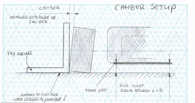
Place the vehicle on a leveled and flat floor.
Make sure the ride height is equal between L and R.
Place the try square as drawn and measure the gap at the top.
Adjust it to the desired setting. 1 turn of the camber adjusting rod equals approx. 5 mm.
The setting used is 1 turn = 5 mm.
2
nd Rear wheel alignment.

Make sure the front wheels are in “straight forward” position.
tape the studs to the heart of the front rims
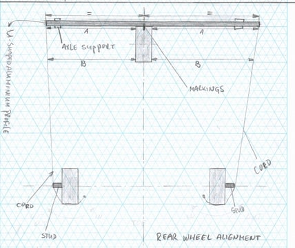
Mark the exact middle of one of the alu beams and mark the exact middle of the rear wheel. Place the alu beam on 2 axle supports against the rear wheel and place the markings towards each other.
Take the cord, knot it to the L wishbone, guide it slightly tensioned over the tire, the stud, through the saw-cut in the alu beam, through the saw cut on the other side of the alu beam, over the other stud and fix it somewhere on the R wishbone.
Now, adjust the wheel until the distances A
left and A
right are equal. Also B
left and B
right must be equal. MEASURE IT ON THE RIM, NOT ON THE TIRE.
3
th Front wheel alignment

Make sure the steering wheel is in “straight forward” position.
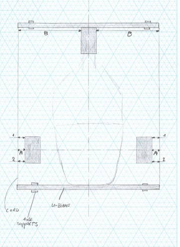
Mark the exact middle of one of the alu beams and mark the exact middle of the rear wheel. Place the alu beam on 2 axle supports against the rear wheel and place the markings towards each other.
Place the other alu beam on 2 axle supports against the nose.
take the cord, knot it to a wishbone, and guide the cord around the vehicle using all the saw cuts in the alu beams.
Equalize distances A
left and A
right measured on the heart of the rim and at the rear B
left and B
right measured on the rear side of the rim.
Take your time!
Now, you can adjust the toe. To give it more “out”, distances “1” must be larger than distances “2”. More "in" is the other way around.
The setting I started with: distance “1” 1 mm smaller than distance “2”.
Be advised that when you adjust the toe, the steering wheel will turn. So, when you measure the setting, make sure the steering wheel is in straight forward. Also, after each modification, turn the steering wheel a little to the left and right to make everything settle a bit.
When you are done, test it on the road to check if the steering wheel is straight. Then measure everything again to make sure the adjustments stayed the same.
Do not underestimate the ride hight. It is best to have it higher on the rear to prevent pressure build up under the vehicle. Because a tR1ke has a flat bottom, this is very important.
I am engineering a height adjuster for the rear. When it is finished, I will post it on the forum.