|
|
Post by ian360 on Jan 20, 2017 12:28:49 GMT
First fit of the rear light tubes done - not finished as clearly too far in from the outer edge. I am going to use hollow threaded bolts to push them out about 50mm from the rear cover which should then make them compliant. At least there is more than 100mm separation from stop lamp (top) to fog (bottom) 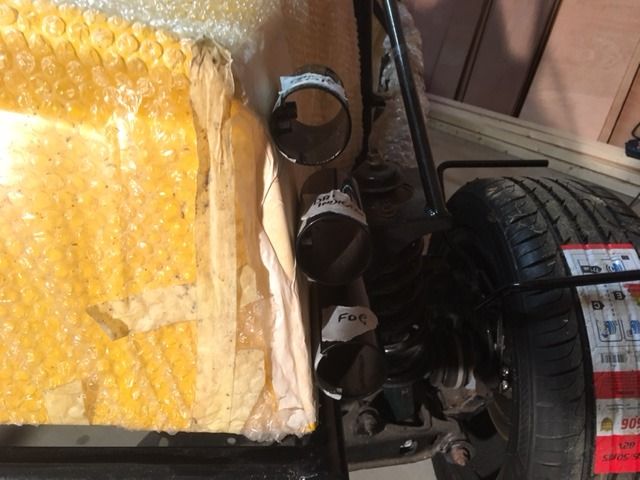
Question / advice on another subject please. I have recently acquired typhoon air induction system at a god price. However, it's the 1.8L version and I only have 1.6L engine. First thing then can I use it at all as compatible items?
If so, it needs a bit of work - 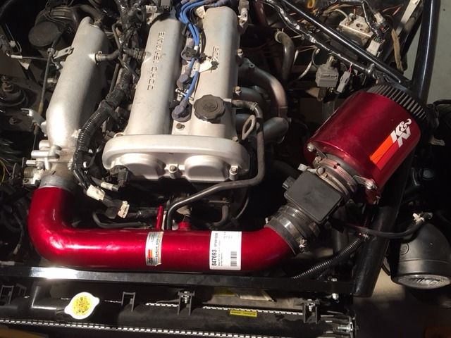
It doesn't fit into the frame.
Options - take off the filter and MAS and just use the donor tube, like this 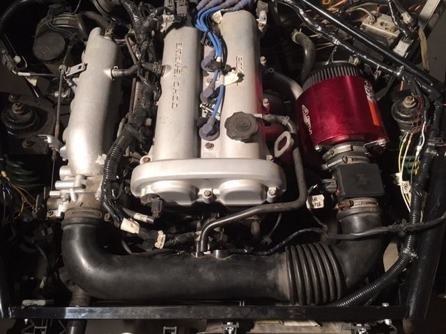
Option 2 - get some 45degree hose to sit the filter further around ,something like this - 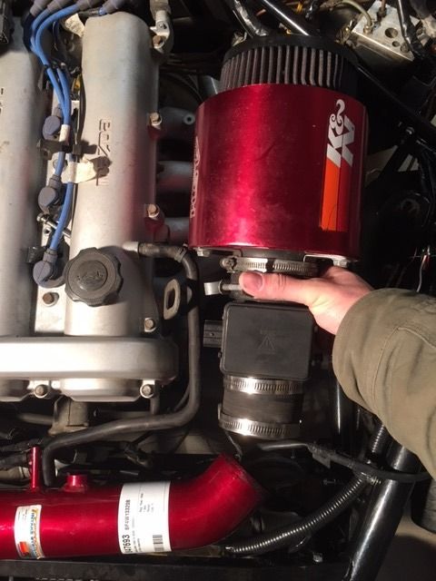
Need to do something as the original air box and filter is too big for the engine bay space. Not sure if option 1 defeats the object of this system?
Appreciate advice Thanks
|
|
|
|
Post by timbo on Jan 20, 2017 22:22:01 GMT
|
|
|
|
Post by gwnwar on Jan 21, 2017 2:00:21 GMT
Why not get a 45 degree hose to move MAF inboard check ebay.
|
|
|
|
Post by ian360 on Jan 21, 2017 11:16:52 GMT
Timbo - yes yours was the idea I copied! Don't think any other builds have used the MEV light tubes yet?
George - are you saying my option 2 above is ok? Or do you mean putting the bend between the MAF and the cone filter?
Any problems using this kit on1.6L?
|
|
|
|
Post by gwnwar on Jan 21, 2017 19:12:41 GMT
Option 2.. use OEM set up.. The plus on using the OEM intake with its "resonance chamber" (box on lower side) is it give a better pull/power in the low end. Straight tube is more for top rpms all the time.. OR for more bling put a hose between the metal tube and the MAF.. Your engine does use a MAF not a AFM right. The tube is just that, a thing point A to point B. If you can get it installed with a couple of hoses. Support it on the filter end to the engine not the frame.. If you get the header hot dip ceramic coated it will cut down the heat near the filter around 20%..
|
|
|
|
Post by ian360 on Jan 30, 2017 11:29:45 GMT
A bit more time this weekend working on the rear cover, think I am about finished now.
Lights all fixed, wires tested and working. The rear was reinforced with some ally and PU'd into place. The one hole missing from this is the one that allows a bolt through the cover tab on the chassis. 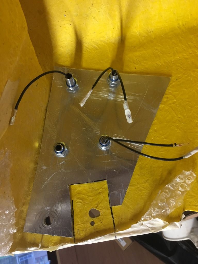
The threaded tubes allow some movement of the bulb holders should it be necessary come IVA time - I am confident (!) that they are correct distances from the edge and each other though.
Set about sorting the fuel filler - a job I hadn't been looking forward to since the start and not overly sure how to approach. Limited engineering experience doesn't allow for anything fancy, and after a bit of messing about with the 'dog bowl' approach decided just to go with the build guide - which doesn't actually say how to fit just to reuse the original donor parts. I have pictures of the MEV company build so used those as the guide. Feeling bold I cut out the hole for the filler. Marked and drilled the fixing holes - they are close to the edge of the hole but I have no idea how close they can be before the integrity of the GRP is lost? It seemed pretty solid, but to satisfy in my mind some extra strength I dropped an odd piece of ally over the neck and bonded it through the fixing as well. 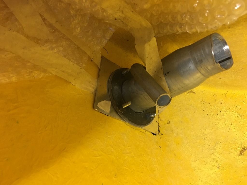
Used some plumbing washers and M5 bolts so from the outside looks like this 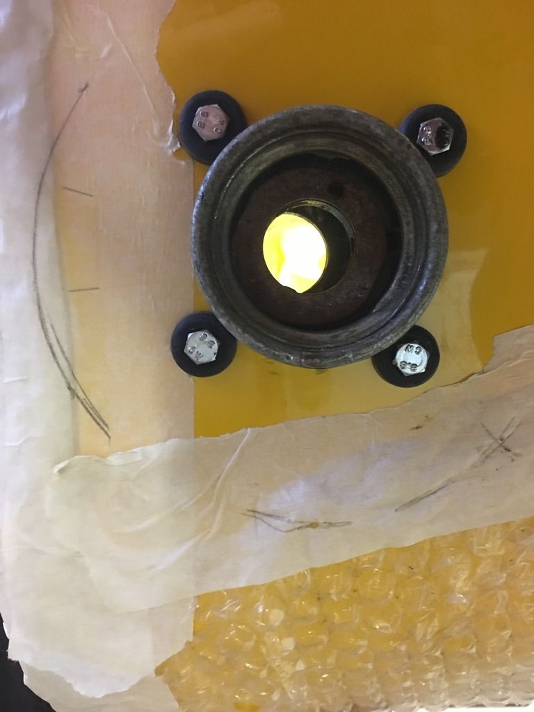
I'm happy that it all fits in place and seems good solid fix. When the cover is in place there is a brace on the chassis which masks the aesthetic a bit, so it doesn't protrude out and look too unsightly.
Next task is how does the filler pipe fit from here to the tank? Plenty of room under the cover but not sure how you get hands in there! Might be some trial and experiment, first a few final jobs just to complete such as tidying the loom run and fixing back the fuel pipes but the tricky jobs on the cover can be ticked off. |
|
|
|
Post by ian360 on Feb 10, 2017 8:52:24 GMT
I need some help / advice please.
Have more or less got the trans cover in place, but I think the transmission / gear stick is sitting too high? 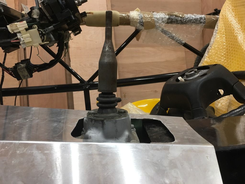
I ask because the gear lever gaiter I bought (original was trashed) doesn't sit anywhere close to the cover, never mind being able to fit from below. 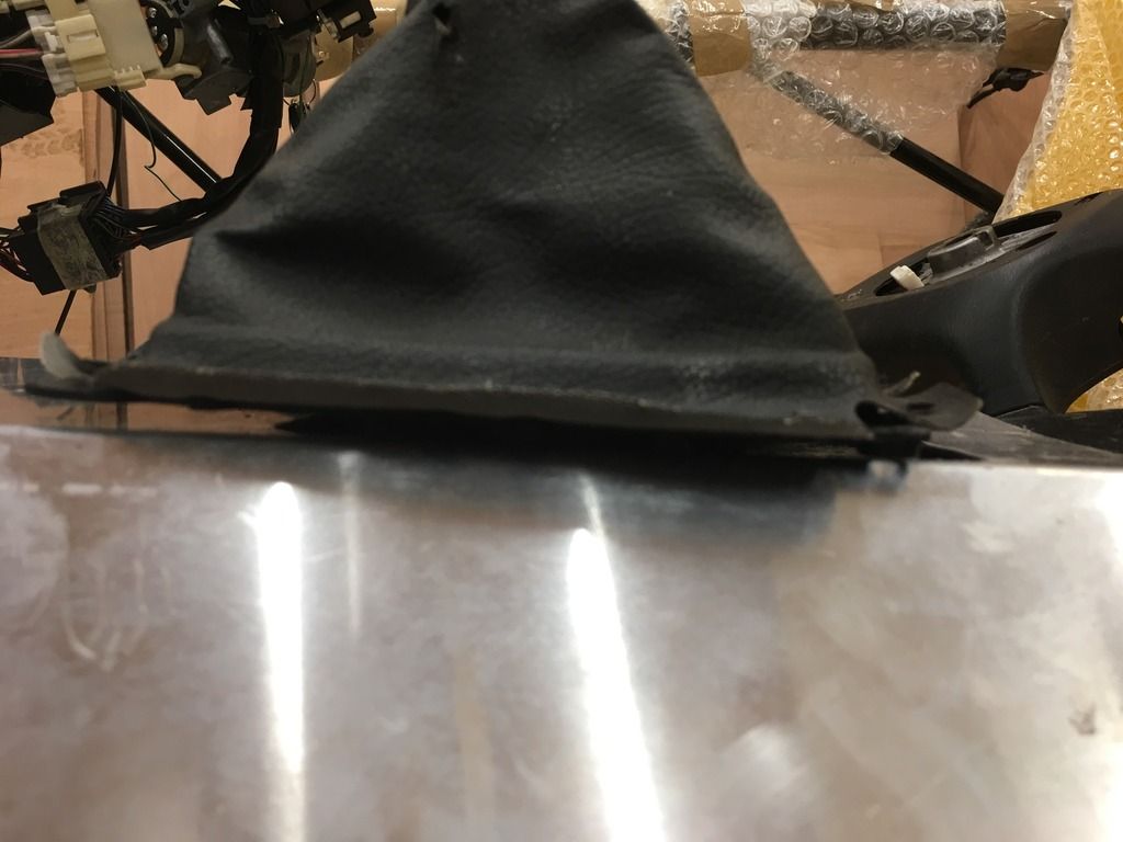
Can anyone advise please. If the trans is too high how do I go about lowering it? I am assuming all gaiters are the same size regardless of model?
Thanks |
|
|
|
Post by h20boynz on Feb 10, 2017 9:12:32 GMT
I had the same problem of the gearbox too high in the tunnel. You can actually loosen the PPF bolts to the gearbox and lever the back of the box down a touch. It will pivot on the engine mounts.
Dont go to far though...the clearance on the front of the engine with the bonnet is tight and pushing the back down lifts the front.
|
|
|
|
Post by ian360 on Feb 14, 2017 9:35:08 GMT
Thanks h20boynz. I did as you say and managed to lower the gearbox about 5mm. I couldn't go anymore, partly as there is a moulding which fouls on the PPF 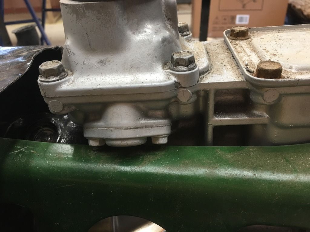 and also I was still just about on the level and had read not to put too much strain on the U-joint. Worst case if the gaiter is too tight I will just get a new longer one made up. and also I was still just about on the level and had read not to put too much strain on the U-joint. Worst case if the gaiter is too tight I will just get a new longer one made up.
Moved on to fitting the wheel arches. Marked up a wheel using the IVA guide minimums 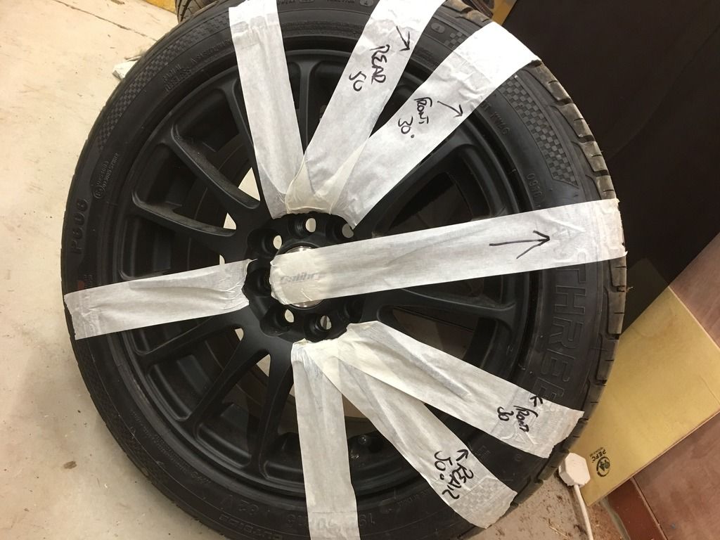
but actually there is plenty of scope on the wings to cover them. I think it is important to get them as far back as possible as this was specifically mentioned in the guide, so as long as minimum 30degree is met to front they will be fine. I started with small pilot hole and then sanded out to size. The stays are three dimensional in that they don't sit parallel to each other and are different heights, or at least mine are (!) so plenty of offering up and sand a bit at a time to get them sitting correctly. I intend to PU in place as per build guide and for a cleaner finish so needed good contact along the length of the stay to the underside. 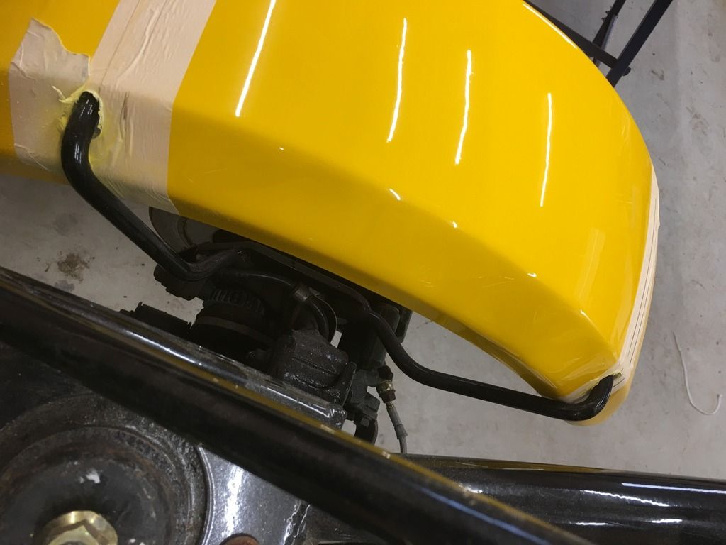
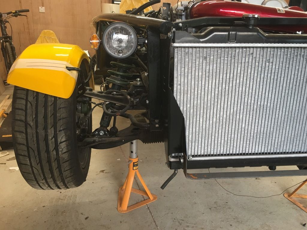
All 4 are now done and pretty close to all being the same fit so pleased with that.. Question - is it necessary to edge trim the guards? I guess better to do this before securing in place?
Also carbon wrapped the centre tunnel, the aluminium had taken a bit of a bashing 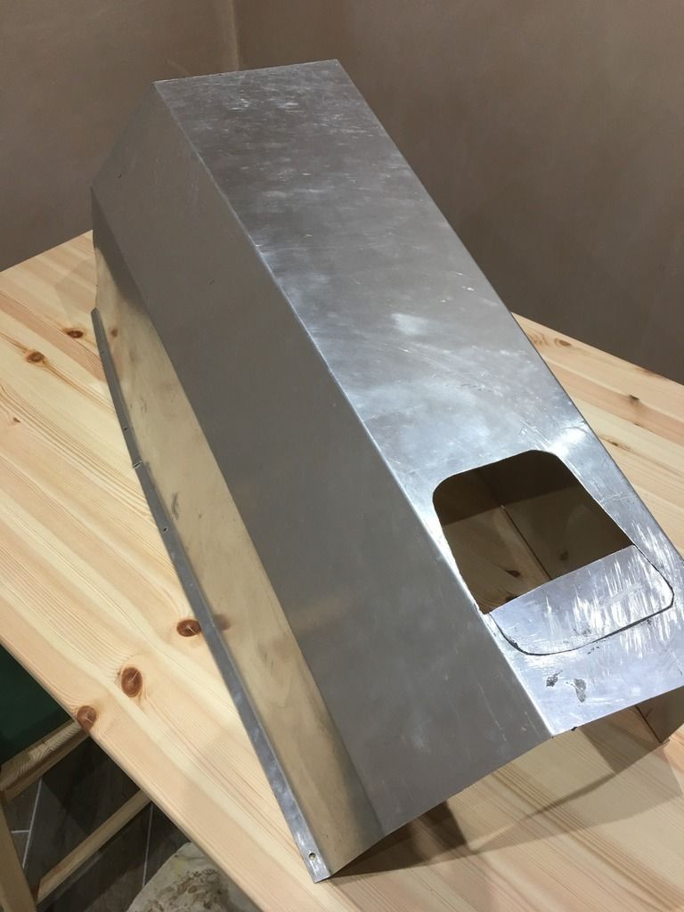
but for a first attempt on a large irregular object I am pleased with the improvement
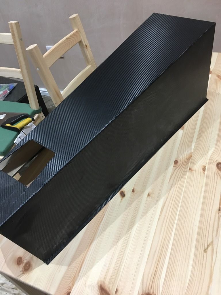
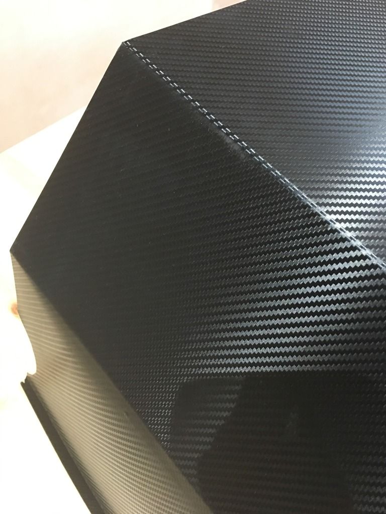
Next item to check off the list I think is the instrument surround.
|
|
|
|
Post by miket on Feb 15, 2017 9:47:20 GMT
Re wings and IVA - it feels the most relevant line is "Wheel arches must be ‘turned inwards’, or have a radius of curvature of at least 2.5mm" rather than the line "Where contactable with the 100mm sphere a glass/fibre reinforced plastic panel edge must have a radius of curvature of at least 1.5mm".
So I'm going with some trim, and yes installed before PUing the wings on the stays - and not just cos the trim will push the wing outboard by a few mills. The trim handles the curves well enough to look good and tidy. Put the join where it's under a stay. My trim won't pull off other than from the ends of the trim and the ends will be pretty inaccessible under a stay, but I might PU the ends to the stays to show the trim's 'permanent'.
Good contact for PU along the length of the stay is tricky cos the wings have a slight curve across them and you might end up removing too much material - compromise in all things eh.
Good luck - I might PUing wings myself later today / this week.
|
|
|
|
Post by ian360 on Feb 16, 2017 10:44:15 GMT
Miket - thanks for info. I don't intend to fix just yet as still some work to do around the body and with my luck I will damage them, so for now have put them somewhere safe out of the way. I thought there was good contact from the stay to the underside along the whole length, but saying that with no experience of PU bonding. Figured a good amount and clamp would see the job through, but will be watching your update for guidance! |
|
|
|
Post by Fin on Feb 16, 2017 13:30:48 GMT
Not that far yet, so haven't studied the guide, but do I presume you PU them off the chassis and upside down so you can get good coverage around the stay? Picked up some parts from another Exocet owner a couple of weeks ago, and he had drilled the stays and fitted retaining bolts from the outside through into the stay as added insurance. Is that on anyone's radar?
|
|
fatboy
Full
   142.5 bhp on a almost stock 1.8
Posts: 197
|
Post by fatboy on Feb 16, 2017 19:05:50 GMT
A little hint on fixing the mudguards use pu as advised but when set glass over them it makes them twice as strong but still hides
all the fixings I did this with my rocket after the powder coat came off the hangers and the mud guards started flapping in the breez
|
|
|
|
Post by ian360 on Mar 28, 2017 8:32:36 GMT
Short holiday interrupted progress recently, but back onto the job list again. Thought I'd tackle the fitting of the bonnet, simple job as one piece item and using the MEV bracket. Not so! The bonnet just doesn't fit as presented, falling short of the dash crossbar by about 2 inches. I had two restricting points - first the side panels hit the headlight mounts provided on the new chassis 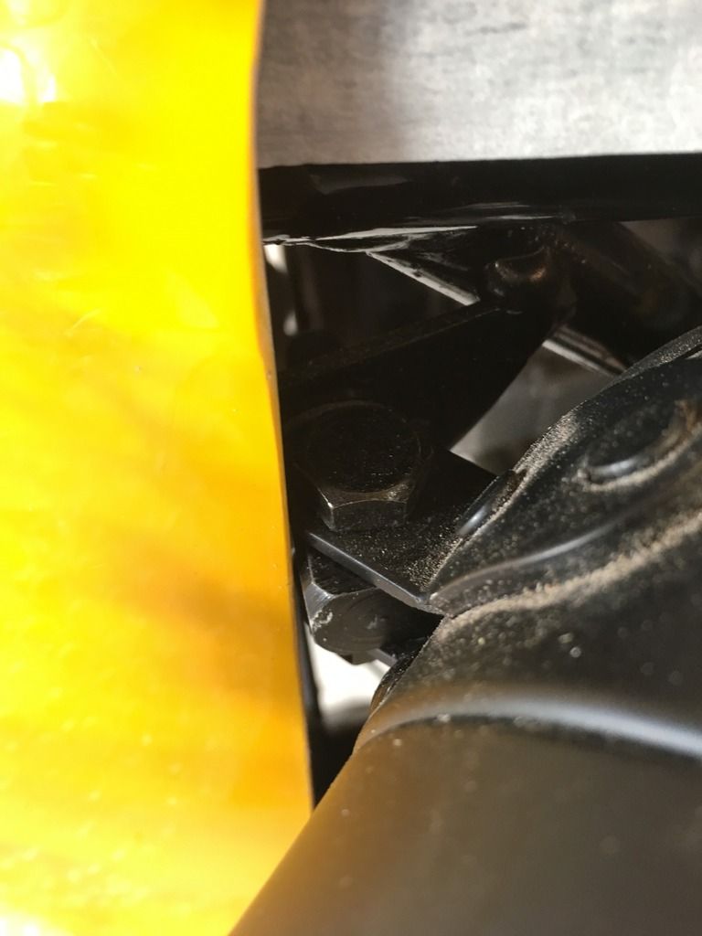
So I removed the headlights temporarily, and second restriction is the radiator / bracket / hinge being wider than the nose itself. I checked with HQ about the location of headlights and seems some moulds could have a bit too much GRP on the sides, easy enough to sand that back. As for the bracket, bit of bending and grinding on the metal and careful sanding of the inside of the bonnet and bit by bit managed to get the fit I was after. Although didn't take any pictures! Once I was happy fitted the catches, another precarious operation involving cutting into the GRP. Actually went a lot smoother than expected. First fitted the pins to the section tube, there is enough room to get hands under the bonnet to mark roughly where they contact the bonnet and drill a small hole through. This can then gradually be opened up to get exactly the position of the pin, and then simply use the catch templates. Lots of taking on and off of the bonnet to double check but get there eventually I used a dremmel to file out the shape 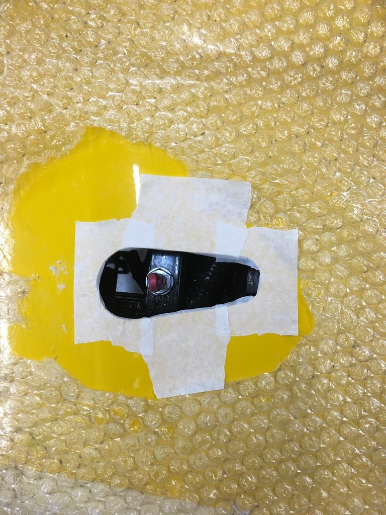
Use the catch itself to template fixing holes 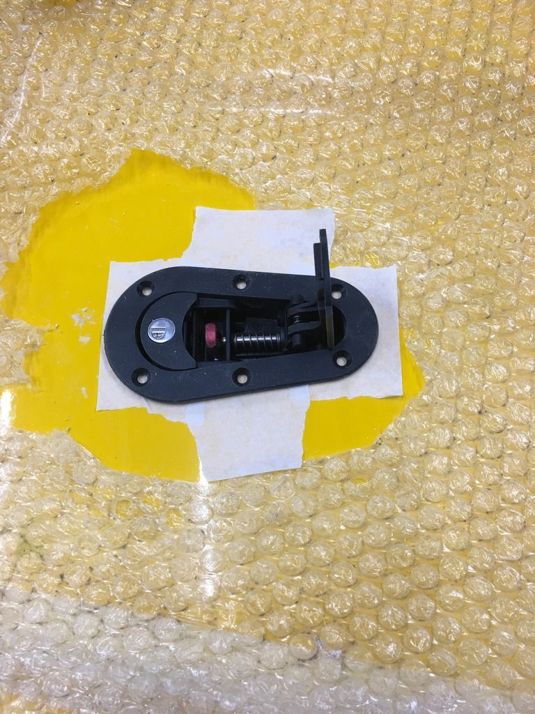
Drill holes 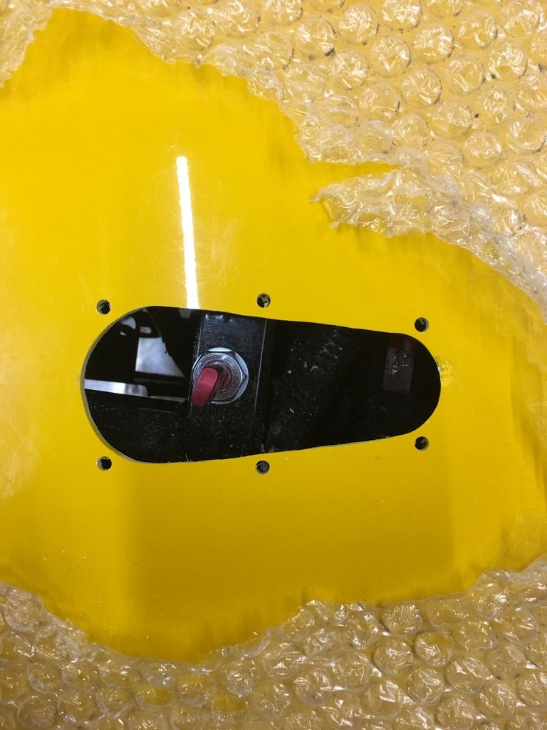
Fit catch and repeat on other side 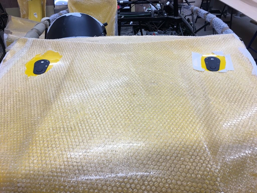
I still have to fix the hinge to the front to complete the job. Another job ticked off was fitting the expansion bottle, the bracket for the bonnet provides a good mounting point 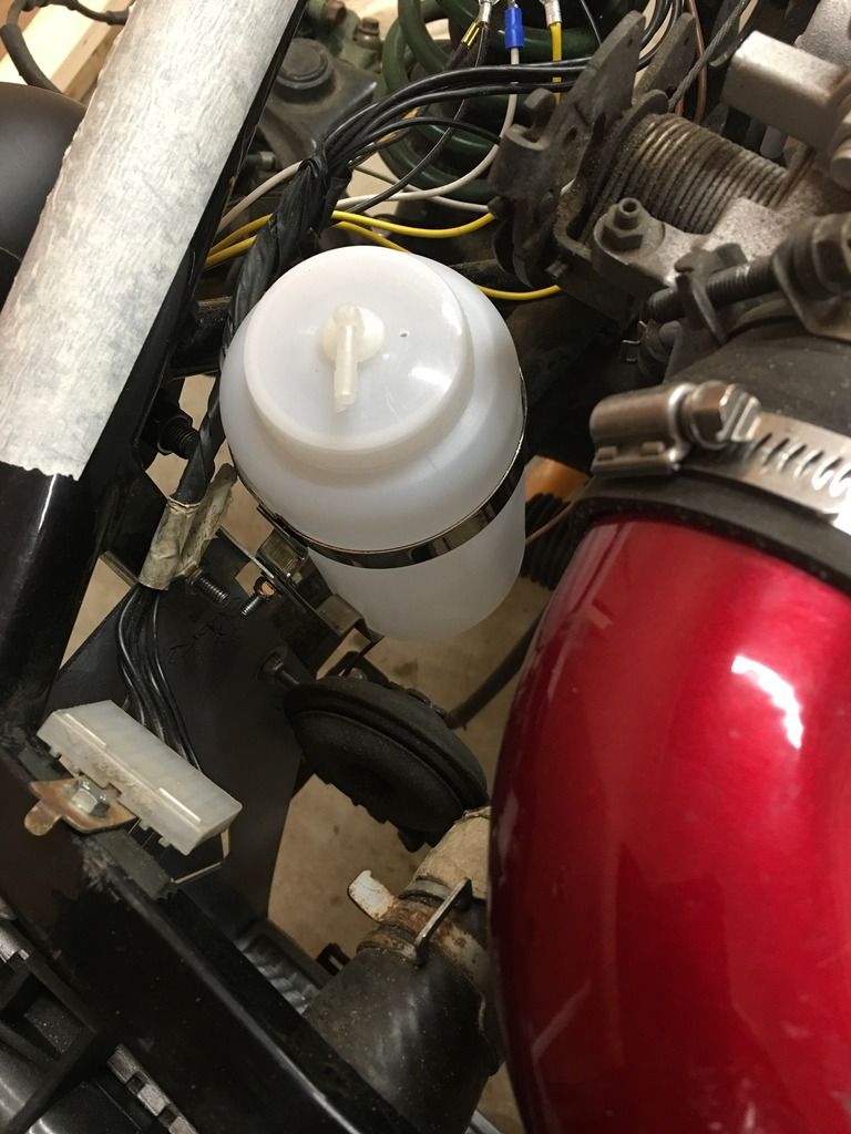
For change of scenery started looking at completing fitting the exhaust, the silencer and back box. I had already bought a new MKII system as the donor was pretty much rusted away. Not the best idea as it just doesn't fit.
Question please - is using flexible exhaust pipe an acceptable and good idea? I don't have access to a welder and even if I did I can't use it, but need a bit of adjustment on the silencer pipe to fit nicely to the back box and meet the hanger fixings. I don't want to start cutting the exhaust if there should be a more suitable solution? Any suggestion to an alternative simple fix? Apart from not using MKII as a donor.............
|
|
|
|
Post by gwnwar on Mar 28, 2017 16:39:30 GMT
Is that top radiator hose clamp far enough on to the hose to seal it.. Looks to far backed off..
|
|