|
|
Post by casesensitive on Dec 24, 2014 15:21:06 GMT
Honestly I don't know, the spaces are there to lower the pedal box so that there's room for the Master Cylinder outlet pipes to clear. I put them on because everyone else did, and I didn't fancy making the front bulkhead more times than I had to (only on my second metal one right now).
It's possible that the pedal box mount is in the 'right' place on the Sonic, they're pretty different structurally up front. If no one else is doing it, then it's probably not needed.
When looking for authoritative build guides I try to use post and read counts to get an idea of the highly-trafficked guides. If there were a way to count the number of unique posters in a thread that'd be even better.
|
|
|
|
Post by casesensitive on Jan 14, 2015 12:44:32 GMT
Ok, after a few wasted weekends, I'm going to have to get lick on. 2015 is the year that this car will get started, and drive around a track. Has to happen.
|
|
|
|
Post by casesensitive on Jan 14, 2015 12:53:10 GMT
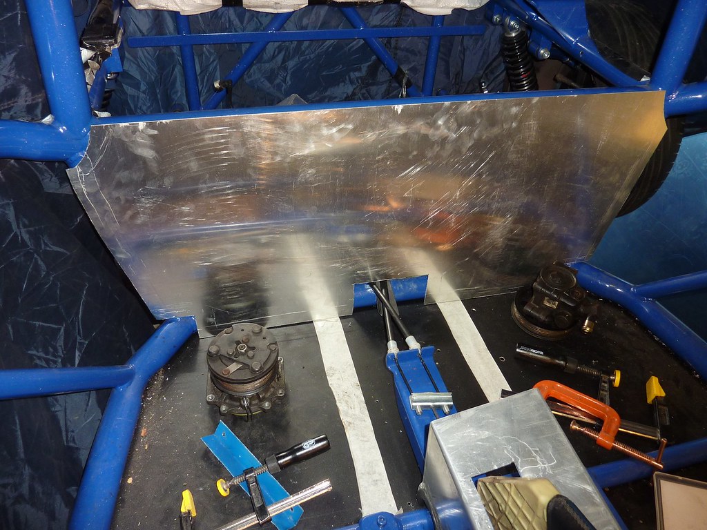
Rear bulkheadSanta brought me a new Einhell ( RT-JS-85) jigsaw to replace the 2 I wore out or broke in 2014, hopefully this fares a little better. - It's really easy to change blades
- It has a a nice holder for 3 blades built into it, should keep the couple I need available and not lost
- Should cut through 8mm of mild steel, plenty for my needs
- You can attach a hoover to suck up the dust as you go. I didn't
- Has an LED light instead of the laser guide the previous two had which isn't as good
I used eyeball, scissors and sharpie to mark out a simple cardboard template for the r/b. For anyone else doing this, start with a piece of cardboard or poster that has at least two flat edges at 90 degrees to each other. Spare zetec parts acting as paperweights.  Who says democracy is pointless? Made a second, more rigid template out of an election poster, cut out with a box knife. Take that Russell Brand.  Not sure what happened to the image of the first cut of the bulkhead, it's pretty primitive at the moment, with just a small cut-out for the pipes and rough edges. I'll file it level and mark out holes for the fuel filler and other bits and pieces. edit: found it 
|
|
|
|
Post by casesensitive on Jan 19, 2015 13:20:07 GMT
Already I've a nagging feeling that I'll be doing this again. After fitting it, the fact that the hole I cut for the pipework was not quite centred (or rather it was centred from the cut outs for the corners, which themselves were not the same), and too big. For now, I'll leave it as-is, and see what the self-made Cover of Randomness hides, and perhaps fettle the corners, add some IVA trim. Speaking of which, I haven't trimmed the edges of the front or rear bulkheads, do we need to? I'm shaping them around the tubes with the rubber mallet but the corner radius is likely to be less than the 2.5mm required. Hmm. Measuring the centre from newly-even corners, and scribing, I left a 2cm 'flap' top and sides to fold in, to catch the tunnel nice and tight like I've done the front. Again though, the second shorter tunnel piece overlaps the long piece by at least 25cm. I can't bring myself to cut it until I'm absolutely certain I haven't missed something. Cut along the green lines with my shiny new jig saw.  Clamp down a big thick piece of iron along the scribed lines, and bash the flaps up with a rubber mallet. Dodgy line on the offside hidden with clever camerawork.  |
|
|
|
Post by casesensitive on Jan 19, 2015 13:32:51 GMT
Engine coverHaving filled the holes in my engine cover from my last ambitious-but-rubbish I had another crack. I reasoned that the more points I attached it with, the less stress would be placed on the fairly brittle GRP. So I bought some piano hinge from B&Q for about €4 and some nice and shiny M4 socket cap screws. The shortest ones they had were M4x35mm, so I spent more time than I'd care to admit cutting, filing and re-tapping them to about 12mm long.   I clamped the hinge in place, drilled 3.5mm and slowly tapped to M4 with a cordless drill. I started with every second one, but for purely aesthetic reasons ended up doing them all (13 per side).  My dad called by after I'd been at this for a few hours, he looked at it for about 15 seconds and asked "did you cut those before or after you screwed them in?" I could have saved myself a few hours by screwing them in and then cutting the heads off with a grinder. Though my way I can take them off and on again I suppose.
|
|
|
|
Post by casesensitive on Jan 25, 2015 1:06:48 GMT
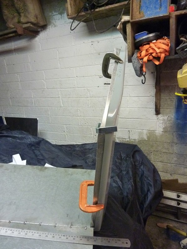
Engine cover After cutting out the engine cover, there's a slight gap, and the 'lid' doesn't sit as well as it might, so I wanted to make an edge that would catch the lid and leave it in place. I'd made a couple of aluminium strips that fit, but they looked like ass, so I figured I'd make a single piece per side. I laid out strips of roughly cut paper, taping them together to follow the line of the outer part.   Fit nicely into some scraps  I then used my digital callipers to mark out a 35mm line parallel to the one left by the outer edge.   And then clamped to get the rough line. I'll file back the lip so that it's even all the way around. I'm going to attempt to get the engine in with the lower part of the engine cover on, if I can, so I'll every mm, lip goes on after engine goes in. 
|
|
|
|
Post by casesensitive on Jan 25, 2015 1:08:38 GMT
Brake linesMade half a plan for my brake lines, rough sketch, may or may not be accurate. Edit: stuff has since arrived, and I've corrected the error I made (20 tpi for imperial MC fitting banjo bolts, rather than 20 mm). As I have to send those banjos bolts back to Venhill, I'll get 90 degree banjos rather than straight, purely because they look nicer. 
|
|
|
|
Post by casesensitive on Jan 27, 2015 9:38:34 GMT
Which turned into this quote from Venhil. I had initially tried to order 'Powerhose' rather than 'Powerhose Plus'; plus is made in the factory to specific lengths, Powerhose you put together yourself. The problem is that Venhill don't have T-pieces in Powerhose! They do sell Powerhose Plus tees, plus complicated-sounding adaptors, but at £8 each, I'd have needed 6 of them, wiping out any cost benefit to making it all myself. Taking out the parts that wouldn't come in RTR's kit, it's £240 all in, which is scarcely cheaper than RTR's offering. For the trouble I went to to figure it all out ( BobN's diagram really helped), I'd really have been better off sucking it up  Highlighted are the parts that are not for the brakes; the 4m throttle cable (I've tacked on a 6mm clevis since), and 30 P-clips to keep it all tied down. They were surprisingly expensive, considering what they are. I was sort of expecting to get a bag of them for a fiver. Anyway, I've got with a go-pedal cable with red liner, and coward-pedal lines in yellow :-> It'll be nearly two weeks before I have them. Trying to buy the RTR/Venhill clutch line from a builder on here who've given up, then I'm just coolant pipes and gear selector cables from a full house of mechanical bits sorted. The small matter of electrics and lights after that :-O update: coward pedal cable didn't come in yellow :-( Plus, Venhill can't actually sell me a 20TPI banjo bolt, and in any case the £10 straight stainless 7/16th banjos were not really what I was after anyway, so the low-pressure banjos and bolts are going back, and I'll have to trawl Ebay for the rest.  |
|
|
|
Post by casesensitive on Feb 1, 2015 22:37:57 GMT
Engine cover do overAfter seeing bingo's work, I felt a bit daft having put the piano hinge on the outside. Reasonably straightforward matter to mount it underneath, but really could have done with some sort of urchin to help. May need to reconsider kids, they'd come in dead useful for holding a spanner the other side of something. I was petrified that having made all the holes with the hinge on the outside, the lid would snag on opening. The lid opens about as far as the roll hoop would allow anyway. When all holes have been made in it, and I'm definitely otherwise finished, I'll sand it down and paint it properly, but I'm not wasting paint now, things have a habit of getting scuffed in my garage.  
|
|
|
|
Post by casesensitive on Feb 1, 2015 22:52:34 GMT
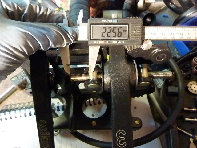
Brake biasA couple of things were wrong with my pedals; none of them lined up, the go pedal pointed about 10 degrees into towards the yellow one, and I hadn't the first notion how to go about tackling the balance bar. Or indeed any notion of brake bias. The Wilwood instructions only made things worse. That and 9.5mm (3/8th?) threaded bar, for which, of course, I had no nuts. They only supply one nut where it seems 4 would be needed. So, where to start? As I had very little hope in figuring it all out myself, I went to Mark's diary, which was strangely not that useful on the topic; he mentions that the Wilwood instructions are rubbish, and then a post later it was all sorted. Enter jacksdad and his considered maths, I straight up copied their design really. Much like the lads, I started by taking the whole thing apart, trying to get some idea of how it all fits together. The first thing to note is that the balance is in no way affected by how far you screw in the master cylinders, only by the relative position of the balance bar. Having done it wrong a couple of times, it's worth noting that the clevii (?) need to be tight against the two giant rusty (>:-| ) washers so that their centres are where the rods on the MCs end up. Like jacksdad, I started with an 8mm ID, 12mm OD crush tube I'd used for my seats fado fado, and I bored it out to 9.5mm with a cheap HSS drill bit (I don't have 9.5mm in cobalt), much silicone lubricant and swearing. I cut about 8mm long, roughly the length of the 'smooth' part of the nut Wilwood supply.   Trial fitting the various bits together, I was aiming for about 1.3 bias rear to front, partly because the rear brakes are weedy where the Hispecs are strong, and partly because that's what the bigger boys said to do. To bias to the rear brakes, I left the gap from the end of the bar to the clevis for the front brake master cylinder at 30mm, and the gap from the other end to the MC going to the rear at 22.5mm.   Balance bar Balance barHaving located the point I wanted my brakes to be biased toward, I marked the horizontal 3/8th bar with red whiteboard marker. I removed the suppled nut, and drilled very carefully through the smooth (thinner!) part of it. That was reasonably ok. But the next hour or more was spent breaking every drill bit I had under 2.5mm. Dremel, cobalt, HSS; that bolt didn't differentiate, it broke every buggering one. In desperation I reached out to other builders, and the dearly-departed deanohonda let me know that you don't necessarily have to drill and lockpin the balance bar for IVA. Thank god. I'll get some 3/8th nuts during the week, and thread lock them on.
|
|
|
|
Post by casesensitive on Feb 1, 2015 23:14:14 GMT
Accelerator pedalA couple of things to tidy up here before my Venhill throttle cable comes next week. I tapped the top and bottom holes to M6, top one for the throttle cable, and the bottom one for the pedal stop, which will allow my pedals to all line up finally. Next to realigning the pedal bracket and pedal itself. First, between the WTF?? bracket on the chassis and the pedal bracket I made, I added 1 more washer to the front M8 bolt (taking it to 2 washers front, 0 rear).  Then another washer, taking us to 3 on the front between bracket and pedal, straightening things out nicely.   Finally, all 3 pedals are more or less facing the same direction and coming out to approximately the same point. Like on a proper car :-) 
|
|
|
|
Post by Stiggy on Feb 1, 2015 23:22:25 GMT
Interpretation of the manual can vary. I would say that 2 nuts locked against each is a "mechanical means" but to be sure of compliance you could consider drilling a hole in one of the nuts and lock wire it.
The following is copied from the IVA manual;
Note 4: Hydraulic valves that only operate automatically and react to
vehicle loading or braking forces are permitted (Load Sensing and
Gravity valves) Manually adjusted valves (other than to permit presetting
the automatic function of a valve) are not permitted to be fitted even if
they are rendered un-adjustable.
Note 5: Bias bars and other mechanical adjusting devices fitted to twin
master cylinders must be rendered inoperable by mechanical means
e.g. lockwiring of components.
Note 6: Adjusting front/rear brake bias may invalidate approval and
breach Construction and Use requirements.
26. It must not be possible to manually adjust braking rates between
axles see note 4 and 5
27. Vehicles fitted with adjustable twin master cylinders that have been
rendered inoperable by mechanical means to comply with RS 26
must have a label affixed on the master cylinder or the immediate
vicinity with legible text as detailed in note 6.
|
|
|
|
Post by casesensitive on Feb 1, 2015 23:48:53 GMT
Interpretation of the manual can vary. I would say that 2 nuts locked against each is a "mechanical means" but to be sure of compliance you could consider drilling a hole in one of the nuts and lock wire it. The following is copied from the IVA manual; Cheers Stuart, I struggled to drill the bar today, nothing would touch it, I'm hoping that either they're ok with locknuts or I come up with something indisputable in the meantime. |
|
|
|
Post by Stiggy on Feb 2, 2015 11:21:00 GMT
I was suggesting you lock wire the 2 lock nuts to each other as you will be able to drill them, not the shaft.
|
|
|
|
Post by casesensitive on Feb 2, 2015 12:43:33 GMT
Ah, ok, thanks, I'm having a little trouble visualising that; should I drill them horizontally (parallel to the balance bar) and lock them to each other? In my childish scribble below, the yellow box is a locknut, and the red bar is the direction of the drill-hole?  Or, do I drill the nuts on either end and wire them to one another along the length of the balance bar as below? Sorry for the simple questions, this stuff is very alien to me.  |
|