|
|
Post by jacksdad on May 23, 2016 15:53:01 GMT
Hi Pocket
Only just seen this, am happy to take some measurements and pictures on mine and post them ill measure distance from bolt centre on lower wishbone chassis bolt to shock absorber bolt centre and take a picture of the shock with lower wishbone level is that helpful ??
|
|
|
|
Post by airforceone on May 23, 2016 16:08:42 GMT
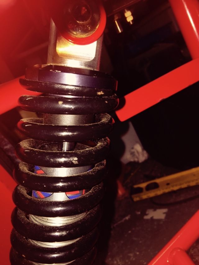
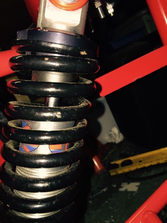
I haven't measured mine but I remember having 14 thread showing at the bottom
of the shock when I set the ride height, don't know if that helps any.
|
|
|
|
Post by Stiggy on May 23, 2016 16:45:06 GMT
I am sorry to see yet another example of RTR product defects.
You need the shock at static ride height to be half way up/half way down so you get bump and droop.
I would first check the drive shafts are well home in the tri bearing sockets when up and down the suspension travel with spring removed.
Assuming that is OK you can cut a small piece off the end of the top arm to gain neg camber adjustment.
Then you can move the lower shock bracket out to give more travel.
Shocks are supposed to be 10" centre eye to eye closed and 13" open, is that what you have?
|
|
|
|
Post by pocketrocket on May 24, 2016 3:03:46 GMT
I am sorry to see yet another example of RTR product defects. You need the shock at static ride height to be half way up/half way down so you get bump and droop. I would first check the drive shafts are well home in the tri bearing sockets when up and down the suspension travel with spring removed. Assuming that is OK you can cut a small piece off the end of the top arm to gain neg camber adjustment. Then you can move the lower shock bracket out to give more travel. Shocks are supposed to be 10" centre eye to eye closed and 13" open, is that what you have? I'd strongly suggest more people check theirs, because I bet mine isn't the only car like it. |
|
|
|
Post by jacksdad on May 26, 2016 21:26:43 GMT
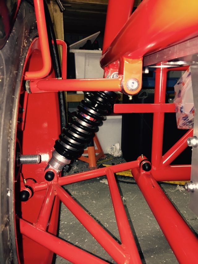   I think mine looks different with the lower bone just a few degrees down from level there is 35mm of travel before hitting the rubber stop horizontal distance from lower wishbone chassis mount bolt centre to lower shock bolt centre is 26 cm hope this helps happy to take other pictures or measurements if this would help |
|
|
|
Post by pocketrocket on May 27, 2016 0:23:16 GMT
Thanks Jack's Dad. I'll measure mine tonight to compare, but, looking at your photo, I'd bet it's much the same
|
|
|
|
Post by Stiggy on May 27, 2016 18:29:00 GMT
Thanks Jack's Dad. I'll measure mine tonight to compare, but, looking at your photo, I'd bet it's much the same I agree, Dad said that the picture of his red bones are shown a couple of degrees down and 35mm travel left to the bump stop, not much room left for bump. Sorry to say that we may have discovered yet another RTR cock up. Perhaps ESC should be given the opportunity address this issue. I just hope that these 2 examples are the only ones. |
|
|
|
Post by pocketrocket on May 28, 2016 5:58:25 GMT
Been looking at this a bit more. A lot of people seem to quote the figure of 30% compression & 70% rebound as what should be aimed for, regarding shock travel. We seem to have about 75mm of total stroke length available to the bump stop. So, we should be aiming for about 22.5mm (30% of 75) of available shaft travel. When I jack the suspension up until I reach that amount of shock shaft showing, the lower control arm is angled down 5deg toward the wheel. I'd have assumed this would then become where ride height should be set. But the geometry seems all out of whack at that  ? |
|
|
|
Post by pocketrocket on Jun 3, 2016 6:10:12 GMT
Finally stopped procrastinating about the rear uprights. The problem I had, was that, for some unknown reason, the uprights I had were different to that of those that everyone else building one of these cars seems to have. The set supplied to me, had a bolt in carrier, which would accept a bearing from the front of an early model Ford Focus. This would have been great except, this carrier would have been spaced laterally incorrectly to suit a standard set of early Focus drive shafts, wouldn't have given a track width anything like what I'd expect it to have, and wouldn't have included any reinforcing webs on the inside of the upright (a known problem on the first "Rockets", where they'd bend). Its worth noting at this point, the earlier Focus has 4 stud hubs & a narrower track width, to that of my later model Focus donor, which is wider (longer drive shafts), 5 stud hubs & larger hub bearings (also larger drive shaft ends). So, I procrastinated over whether to; A: convert the front hubs to 5 stud, to match my existing rear hubs, brakes & use my existing wheels. Also converting the rear carriers to accept the larger bearings & drive shafts, but requiring drive shafts to be shortened. or B: replace wheels with 4 stud. Replace rear hubs, brake discs & drive shafts with earlier model Focus but would require drive shaft ends to be mix & matched to suit later model gearbox. either way required the modification of the rear upright & bearing carrier, & drive shafts. So, after deliberating on this for weeks. Many beers consumed & many measurements taken. I decided to go with plan A. Reason being, other than shortening the driveshafts, everything will remain pretty much standardized from a common donor & saves buying new wheels. Same mate, that owns a machine shop & has done previous work for me, machined up some new bearing carriers (leaving the ID slightly undersize). I spent quite some time working out the correct offset for these to be welded into the upright, that would give a reasonable track width, in relation to the front. End result, assuming my measuring & calculating is correct, rear should be about 20mm narrower than the front. I'm not sure what a correct number should be, but I'm confident this will be in the ball park. I then tacked the carrier into the upright, tacked the reinforcing webs onto the upright & carrier, pressed the whole lot straight again. Then welded them out. Pressed them straight again (they pulled like a expletive deleted). Then had machinist mate bore the carrier ID to size (0.002" interference). Left this step until last because I was worried once I welded around the carrier, the ID would no longer be correct. I think they should be good to go.... hopefully 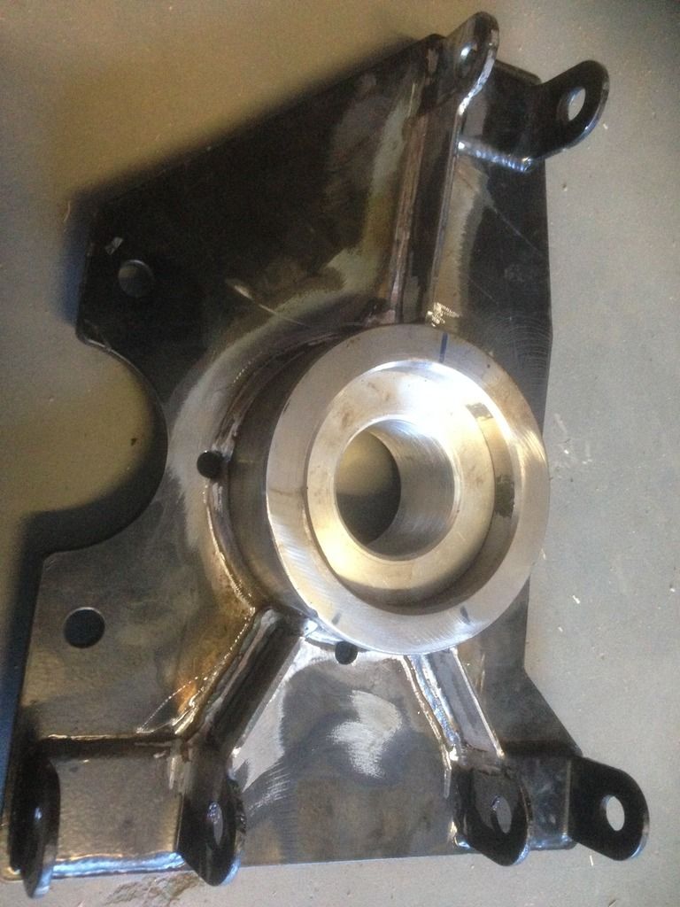 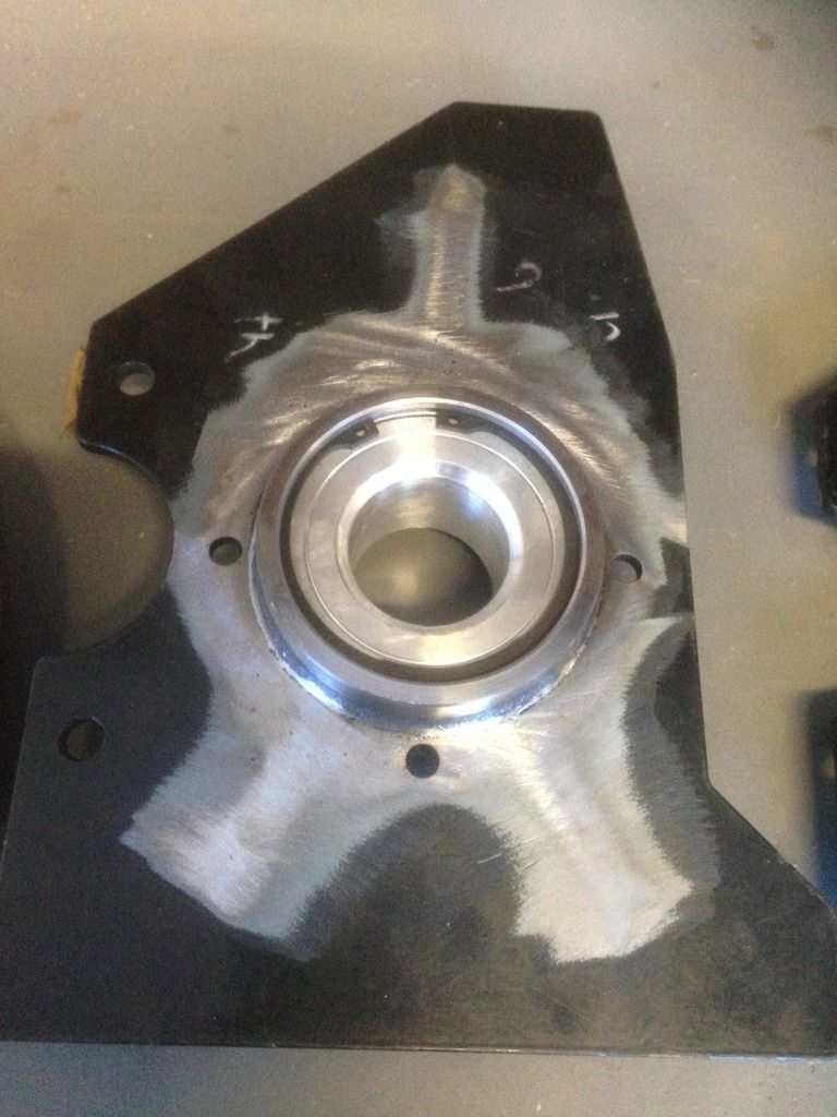 Also had machinist mate, knock up some dummy aluminium bushes, to replicate the hub bearings, until final assembly. Saves trying to press bearings/drive flanges in & out of the carrier while mocking things up. Although I'm far from being a machinist, I need to seriously start looking at getting a lathe and/or mill for some of these smaller, more basic machine jobs. |
|
|
|
Post by pocketrocket on Jun 4, 2016 6:53:26 GMT
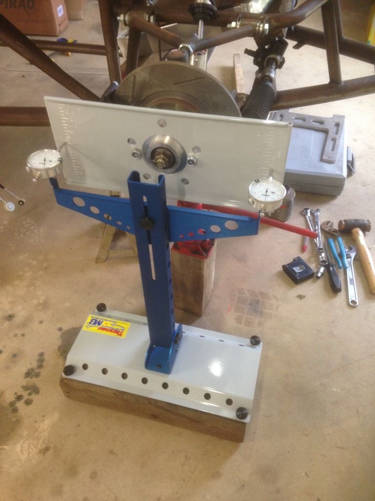 Ain't this a fun job.... No wonder a bloke drinks Not 100% sure, but thinking the rack might be a tad short. Might have to draw this out to see, because I seem to be going around in circles at the moment. |
|
|
|
Post by kiwicanfly on Jun 4, 2016 8:10:14 GMT
Presume you are measuring bump steer? I did not have access to such a flash device.
Lengthening the rack is the same as shortening the arms so seems like we both found the same problem.
Out of interest what are your results looking like numerically?
|
|
|
|
Post by kiwicanfly on Jun 4, 2016 9:20:37 GMT
Backing up a post, changing to later five stud hubs makes more sense. Not because of the number of studs per se but because of avoiding the 4x10⁸ stud pitch from the earlier Fords.
Assuming your wheel options in Oz are similar to those here 4x10⁸ is as rare as hens teeth whereas 4/5x100 and 4/5x114.3 are common as.
If I had known the trouble I would have trying to get a second set of wheels I would have specified different hubs from the beginning.
Cant believe you got the uprights you did stunning but not in a good way.
|
|
|
|
Post by pocketrocket on Jun 6, 2016 2:01:27 GMT
I have been checking over travel of 3". 1.5" either side of ride height. Just recording at 1/2" intervals. It started out under compression, toeing out 0.036 at 1/2. 0.145 out at 1 then 0.242 at 1.5". Then in rebound it started out with 0.069 toe in at 1/2, 0.083 in at 1" & 0.065 in at 1.5". I took the spacer out & remeasured with the rack bolted straight to the mounts. Compression went 0.036 out, 0.080 out then 0.141 out. Rebound went 0.040 in, 0.073 in then 0.103 in. Remembering this is measured on one wheel, so the measurements will be doubled for true toe readings. I haven't really looked at it yet today.
I'm starting to think the rack might need to go down more
|
|
|
|
Post by pocketrocket on Jun 20, 2016 7:50:57 GMT
after going up, down round & round on the bump steer, I've arrived at maintaining 1/16 (1.5mm/0.060") give or take a few thousandths of an inch, toe out during bump over 3" (1.5" compression/1.5" rebound).
for the record, ended up lowering the rack 2mm
So, one can only assume, the chassis we get over here are different to those that were sold in the UK
|
|
|
|
Post by mawdo81 on Jun 20, 2016 13:07:40 GMT
How did you lower the rack?
|
|


 ?
?


