|
|
Post by R2S on May 10, 2021 17:02:36 GMT
Back on the car in earnest now, seats fitted (temp until appropriate IVA bolts arrive). Original plan was to mount runners onto angle bolted to cross rails thereby avoiding bolts protruding through floor. Realised drilling cross rails would be almost impossible due to floor being in place so went for the original design and holes drilled. Law of sod came into play, four of the eight holes interfered with floor fixings (rivets) as installed, two had to be drilled out as hole was in exact same place others had to be drilled out to allow large washer to sit flush (these aren't in place yet so no photo at moment. Whilst getting seat ready to install came across first problem, the seats had been made in such a way that the standard MX5 runner bar to allow sliding couldn't move so had to take front of seat cut back and reinstall (wifes upholstery stapler was a godsend). .jpeg?width=1920&height=1080&fit=bounds) Seats in place next potential issue, the harness mounting sleeve isn't central to the seat position which means one strap from harness will come to side of headrest whilst other will pass through between headrest legs. No idea if this is IVA compatible but will check out with fellow kit builders who have been there. 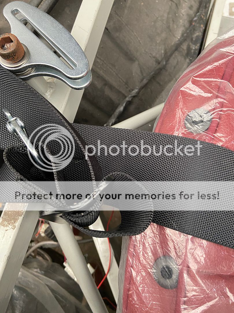 Really pleased with central upper rear mounting brackets I've fabricated, I think others have used rubber bobbins and have body resting, I have gone opposite direction with brackets bonded to body and bolted to the rear supports on the chassis with a dense foam washer between both surfaces. 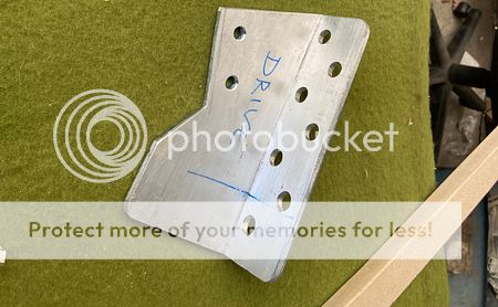 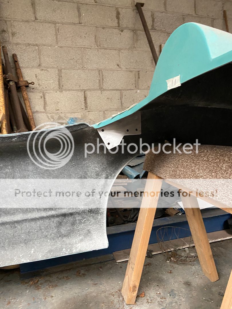 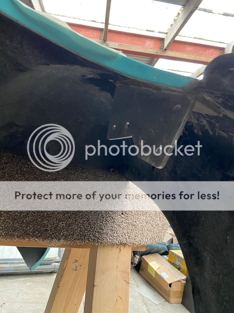 Front upper cockpit mounts in mid fabrication but I've arrived at a design I am happy with, basically a pice of angle on the flat ali over front bulkhead to which is bolted an angled piece of 5mm ali again mounted using dense foam washer. Front mounting bracket templates made and plan to make these on this weeks trip to the workshop. Once all mounts in place next job is to fabricate the exhaust (rear section) which will connect to a standard MX5 system just rear of rear subframe (basically replacing MX5 rear box with something that fits the kit). |
|
|
|
Post by R2S on May 16, 2021 9:01:59 GMT
Bit more progress this week, body mounts to front of cockpit almost complete just need to cut out where plate extends into engine bay (will follow line of body as per line marked on surface. 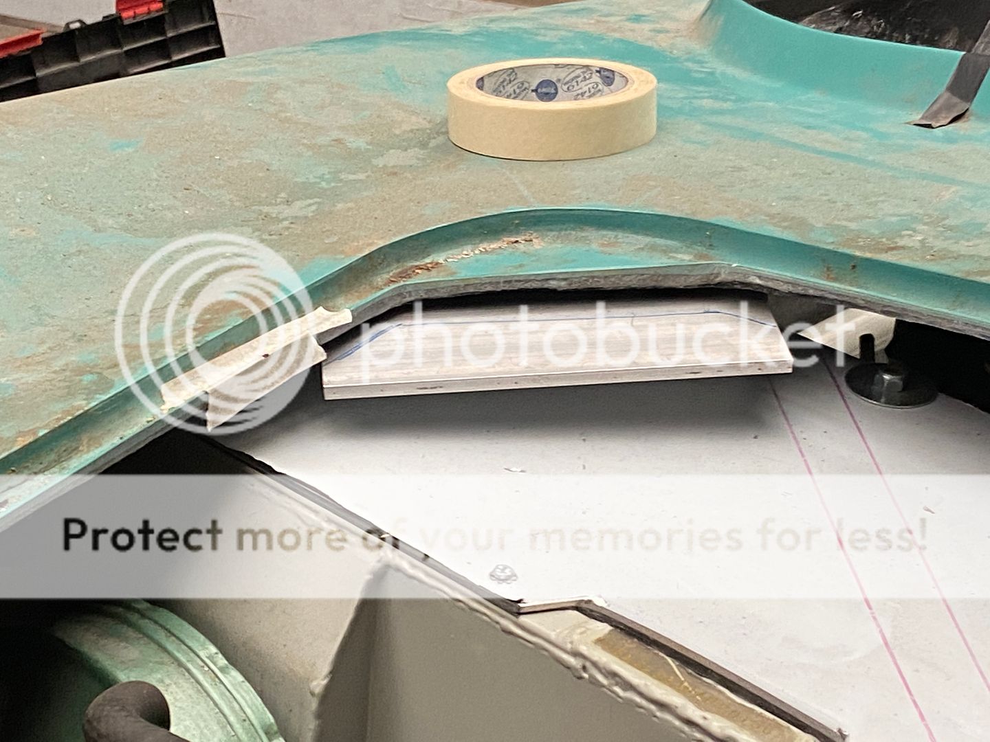 Finally got dashboard in position I want it, probably 75mm to the right of original. This meant I had to cut quite a lot off right end, face and top, to fit under body. 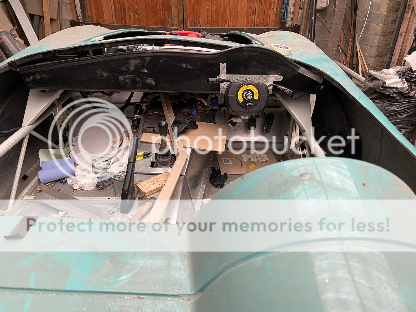 Quite a gap between top of dash and body but plan is to fill this with foam (could be left open to act as heater  ). Made sliding brackets to fit dash to tangs at either side of the car. Plan is to fit these using bonding to back of dash and to bolt to chassis, once bonding agent has gone off sliding fixing will allow adjustment. Brackets made, top face to be drilled and tapped, lower face to be slotted, just need wing nuts before fitting. 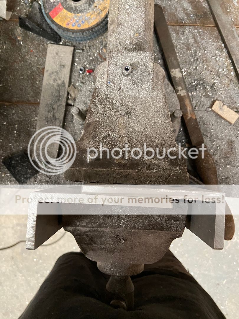 Having raised body on chassis (to get over any issue of rear lights not being high enough for IVA I know have a problem:- 1. I can leave GRP body as is and bring lower edge into top of chassis bottom rail, this will make a square section visible from side albeit I can paint body colour or more likely black so as to 'disappear'. 2. Other option is to cut body horizontally and insert strip say 50mm wide. In reality I will probably do 1 for IVA and once running, and pre paint job will convert to option 2. (Hope that makes sense) 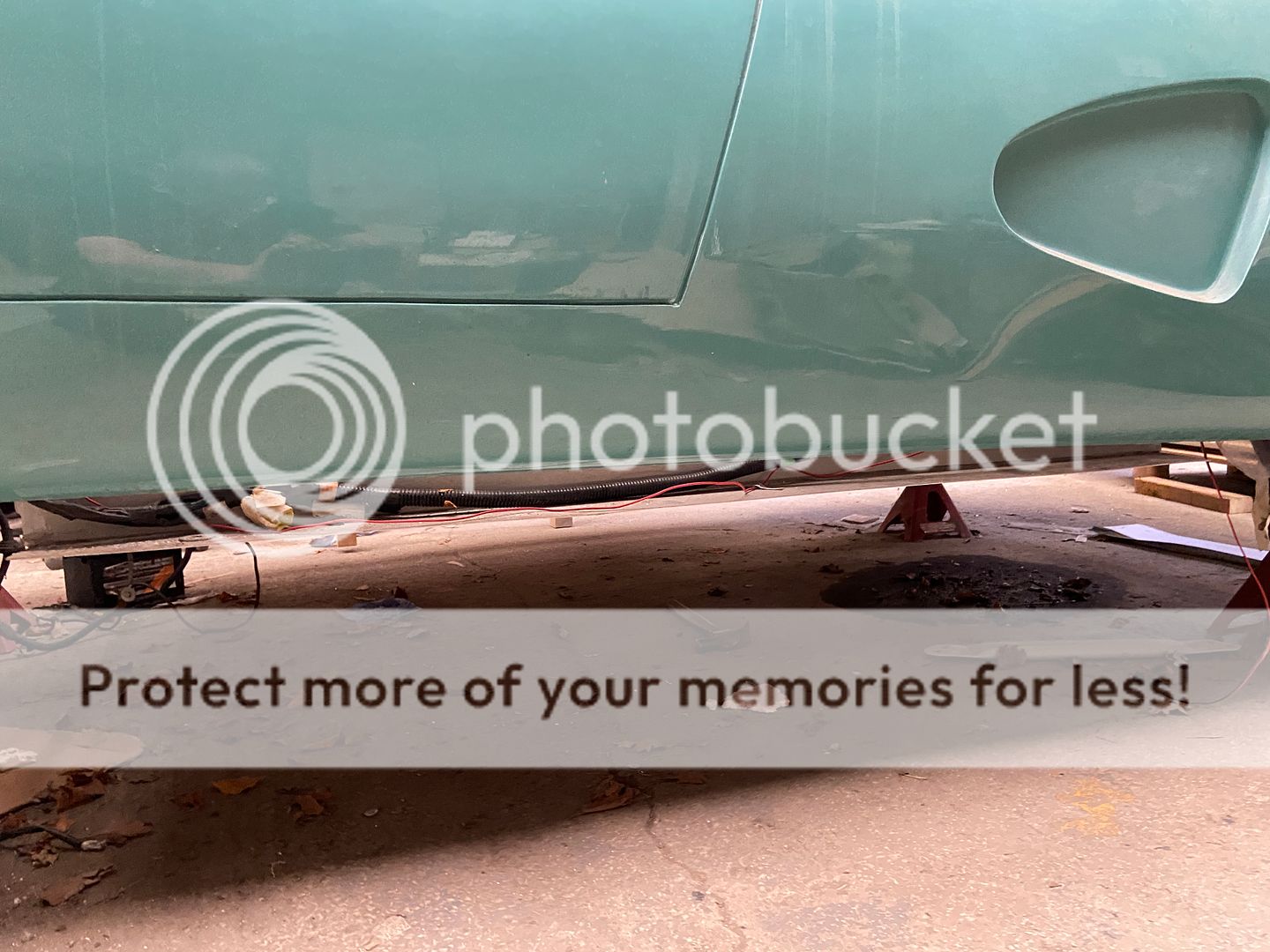 Next weeks challenge is to fabricate the front body mounts, template is made just can't decide whether to use mild steel and weld up or to stick with the ali angle I have been using. |
|
|
|
Post by R2S on May 21, 2021 21:09:47 GMT
Another day at the workshop but no photos to share.
Dash board mounting brackets finished off with sliding clips to allow some adjustment back and forth. Had to try a couple of methods for fixing chassis side in place temporary until I can get in and drill.
First attempt to work in cockpit under dash upside down (the sort of stuff that was never a problem) but age means its not as simple as it used to be!
First effort using molecular metal as an adhesive, fail.
Second method used seam sealer to locate the inner face acting as adhesive will go back over weekend to fix dash bracket then again early next week to remove dash, strengthening dash side fixing by glassing in and chassis side bracket by drilling and bolting in place.
Ran out of time to establish bolt lengths for seat fixings but will do this when dash fixing, and order appropriate bolts and washers.
|
|
|
|
Post by R2S on Mar 31, 2022 20:33:34 GMT
Some time since last update progress has been slow (nothing new there then )with no work between Sept 21 and Feb 22. As is clear from my build two steps forward usually result in one back and this is the case with the harnesses I bought. Previously wrote about how I'd bought 3" TRS four points, and was looking at relocating fixing point. After much deliberation, and as a structural engineer, I decided the single mounting is at the strongest point on the cross rail where it meets the stiffeners so four point harnesses replaced with 3 point 2" TRS items. Initially bought one to see if it was ok, this proved to be the case but the upper single strap before it splits into two is way too long and only a couple of inches is needed. After a chat with Gareth at GSM Performance it became clear that the three point harness produced for Westfields (with the very short upper strap) may be way to go, I have one on order just waiting delivery and I'll update once received. The other area where I've probably spent a disproportionate amount of time is the battery. I decided on a racing batter and decided to locate it behind the passenger seat low down on the floor. This area has lots of space as seat back is inclined. I decided I wanted the power cut off switch in the corner 'web' to the left behind the passenger but easily accessible from outside the car. This meant the +ve lead comes to the battery from the centre tunnel whilst the -ve comes from under the switch. This brought with it another problem, because of the position of the terminals on the battery and having +ve closest to tunnel terminals are very close to the rear bulkhead and there is the potential to short if anything dropped on +ver terminal touches bulkhead. After a bit of thought I've installed a sheet of perspex between battery and bulkhead also coloured this to indicate without doubt which terminal is which.   Whilst working on the lower rear bulkhead I was also trying to work out how I could get the large connector block through the bulkhead into cockpit without drilling large hole. Answer was to cut a hole large enough for the grommet but slotted from bottom of sheet and use a cover plate to infill slot (hope that makes sense). I've joggled the cover piece so externally where it meets the frame its flush with the rest of the bulkhead. Lots of messing and trying new things with this lower panel meant there were a number of scuff marks so I thought I'd try to mimic machine finish, I think it looks OK my brother thinks its dreadful.  Latest issue I am grappling with is fuel filler, racing style cap I've bought from CBS doesn't have the vent pipe I need to connect straight up to MX5 tank. Folk have offered up ideas but none are workable so I think I am going to resort to connecting original neck just below new filler using short piece of rubber if it lines up. Quick question for others, anyone know how to remove the flap in the top of the MX5 neck? I suspect once I move this section of pipe further away from fuel inlet fuel pump filler will no longer reach the flap.  In terms of next steps I need to install the angles to the inner side of my 'no door' body to support the flat pieces that sit between chassis upper rail and body. Lower pieces from body to chassis now in place on body, original instructions are GRP body fits to 75mm extension of floor but having lifted my body on chassis it wouldn't reach so filler pieces were needed. I've fixed these with rivnuts and button head screws rather than rivets so as to be able to remove and get into cill panel (hope to have exhaust in passenger side some time in future). Whilst seats are not in car at moment all fixings and locations are done they are just out to give more room and avoid damage. Whilst they have heated pads installed i don't plan to connect them for IVA. Also made a start on fitting rear lights and whilst not wired these are all now in place. Due to fact I've moved body back on chassis the rear MEV frame is not long enough but plan to use ply panel between rear bracket and body to make up gap so again another new job on the list. Soon be time to drop body back on and lower car to ground then sort out lights etc.  |
|
|
|
Post by ancsportscars on Apr 6, 2022 8:42:50 GMT
  Gary, I modified the donor fuel filler neck to suit. (see 'Sept 2018' in my build blog on ANC website) |
|
|
|
Post by R2S on Apr 6, 2022 9:23:23 GMT
Thanks Andy did you remove the one way flap?
My filler is going exactly same location on rear deck so your layout would work but shouldn't breather be at filler point rather than half way down? Bearing in mind it passed IVA so assume not a problem re design but does tank fill ok without blow back or slow fill?
|
|
|
|
Post by ancsportscars on Apr 8, 2022 13:33:44 GMT
I believe I removed the flap. (Done some time ago now so can't remember) Filling is a little slow as you can indeed get blow back (but you ain't leaving a petrol station any time soon, anyway - as there's always someone who'll want want to talk about the car!)
I was more concerned with finding a solution to getting the differing diameters between the Aston style filler neck and that of the tank's inlet stub to marry up - as well as incorporating the breather tube from the tank.
|
|
|
|
Post by R2S on Apr 8, 2022 17:29:59 GMT
Thanks Andy, I've been building so long I rely on this blog as a reminder of what I had planned, re the fuel filler think I can fit mine almost at the base of my Aston racing filler neck plus locating vent to rear should aide filling.
Not sure if its helpful for others (or upper seat belt fixing in ANC is moved) but the 2" TRS Westfield three point harness seems to be the way to go, a few quid cheaper than the standard three point as the top single strap is somewhat shorter, you only really use a couple of inches of the single strap in the Replicar with original mounting point. I may re consider fixings post IVA and add another so as to be able to use 3" TRS four point harnesses I originally bought
|
|
|
|
Post by R2S on May 3, 2022 14:56:43 GMT
So some time on the car today and as per Andys suggestion I've decided to use the original fuel filler neck. I cut just below the flange which also removes the upper sprung flap.  This is the sprung upper flap now surplus to requirements.  Cleaned top of pipe to give flat finish  Almost same diameter as lower end of Aston Filler cap, plan is butt joint both using a short piece of rubber pipe as connector.  No plans yet to shorten other ends of Mazda pipe until I know exactly what is required. Also tidied up exposed hand brake lever fixings which had developed a coating of rust so long since I installed, cleaned off and a coat of clear lacquer should keep the rust away for a while. Internal side body panels all cleaned with overlaps joggled and ready for final fit. Ran out of time today but all ready for fitting next time. |
|
|
|
Post by R2S on May 19, 2022 8:54:05 GMT
New flexi pipes for the shortened filler neck arrived and will now be put in store 'til after body on, hopefully next couple of weeks (providing I can get 5 helpers to lift body), some progress tidying up MX5 wiring haven't cut any out, just in case, but have separated out required and not required and tried to tuck that not required out of way.
Dash board trial fix this weekend so as to be able to finish wiring, setting position of, hazard, dash light dimmer, fog light switch etc (likely to be in completely different position to MX5 although I am considering cutting out the dash switch holder and mounting to Replicar Dash).
Can't make my mind up whether to keep cigarette lighter as a power point or whether to use this to feed heated seats (I'll ponder that one for a while, like most things).
Will take some photos over weekend and load.
|
|
|
|
Post by R2S on May 26, 2022 12:19:49 GMT
Tidy up of donor loom was going really well until I offered up dash.  |
|
|
|
Post by R2S on May 26, 2022 12:34:18 GMT
My body is mounted slightly further back than normal and therefore dash moves back due to dial 'bubble'. So new piece of ali ordered which will span the gap (new piece 1400mm x 400mm). Having cut the hazard warning hole in middle of dash I am assuming (dangerous I know) IVA will expect fog light switch to be clearly visible therefore my original plan to place to far right next to body (therefor somewhat hidden) is a non starter. Plan is now to locate the switches mid way between hazard and dials side by side and vertical rather than horizontal. At this time only two switches are fog light and dash light dimmer and whilst i am not sure they will be in keeping with 50's theme I'm determined to make use of as many donor parts as possible.  Things are getting rather congested over the steering column and this is another reason I'm rethinking anything placed to right of column.  Wiring in the photo is the alarm (fitted to the donor and I dare not remove) and the redundant abs clip and associated wiring, this is now all clipped up (disused wiring) and bolted in place (alarm).  Should add this is the first time I have used the 'add image to post' wasn't there when I first started this thread way back, hope photos are appearing as its way simpler than the old photo bucket or google route. |
|
|
|
Post by R2S on Jun 24, 2022 18:04:44 GMT
New piece of Ali to close gap to dash (referred to above) now done, rear bulk head now fixed in place complete with seam sealer (its there to stay). Re-located earthing strap from petrol tank to both rear subframe and PPF. Also sorted earth lead from chassis (PPF) to battery just waiting for seam sealer on bulkhead to go off and fixing brackets adhesive to set before placing.
On the usual two steps forward and one back those who have kept up with my build will have noticed I've removed the dash board photos and description of work, having tried to fit the MX5 pod the centres of the dials being raised means pod has to sit back some 8mm which means pod won't fit under the cowl. After careful consideration I've decided solution is to cut out the front of the grp dash, mount the pod to a piece of ali (will be painted) and then overlay this onto dash (just as Stuart did in the red, now green, demonstrator, I really do need to stop trying to invent the wheel). This gives a couple of benefits, allows me to lower dash in GRP I've already cut and means in future if I need to address any issues with dials its only this panel rather than full dash needs to come out. On the up side I've managed to fit the standard MX5 fog light switch into GRP dash, had to carefully cut out the holder from donor dash and fix into grp, fits really well but I'm not sure I like it.
Once this is done I'm ready to final fit body.
Photos to follow.
|
|
|
|
Post by R2S on Jul 13, 2022 9:39:13 GMT
OK latest on the dash, sacrificial panel cut to allow definition of outline and fit to GRP panel before cutting 3mm thick panel. 
Final 3mm panel dimensioned up for holes but awaiting outer perimeter marking from test fit.  Rear bulkhead in and battery fitted wires ready to be clipped in place.   |
|
|
|
Post by R2S on Jul 31, 2022 10:11:59 GMT
Well back in February I was rather pleased with myself that I'd managed to line up the dials from the plug and play MX5 dash on the GRP dash that comes in the kit.  |
|


 ).
).


