|
|
Post by casesensitive on Aug 24, 2015 19:50:49 GMT
And some things that went less wellMy main goal this weekend was to make the thing make some noise, ideally a loud one. I hijacked a fuel line thread over in the technical section until it became clear my issue was not (solely) fueling-related. Essentially, I plumbed up my Focus kit (Tank to extended-fuel sender to filter to long 8mm ID hose to jerry can, and wired up pump and infernal Driver Fuel Pump Module (or some combination of those words in another order) to default connectors on largely unmolested loom. 6l of fuel just to wet the pump a little. I connected up the power, with my lovely new battery isolator, and because it turns out my expensive racing battery is junk, I connected up my 2.4L tractor-juice fueled daily driver's monsterous battery to provide a little more umph in the Charging Amps department. I was all set to see some fuel get pumped, a starter turn over, and ultimately, maybe, some un-exhausted Zetec shoutyness. CBS ultra-flexible hose worked a treat   Put the fuel destination outside where the wind would at least disperse the fumes (later connected to fuel rail in vain hope something magical would happen).  In case it all went horribly wrong In case it all went horribly wrong All set then for great things. Big cup of NOPE! The sound I thought was the fuel pump kicking in was actually a whir from the throttle body of all places, nothing happening down in the tank It's almost certainly a wiring issue, which is frustrating, because I basically haven't changed much of anything from the stock loom, save maybe being short a few earth points. I took a tap directly to the starter (negative of Alfa's battery to body of solenoid, pos to this scavenged piece of starter wiring from my old Puma), and it works. Starter spins when it's given power, solenoid clonks when it has power. Hmmm. Note, for this test, with all the sparks etc, fuel lines were tidied, fumes at a minimum. www.flickr.com/photos/43278150@N00/20814244746/in/dateposted-public/This was already pretty late in the day, and it was bucketing down, so I parked it with a silent admission that I'd strip out all the wiring and start from first principles, one circuit at a time until I can make it fire. The quick payoff looks like it'll have to wait.
|
|
|
|
Post by casesensitive on Aug 30, 2015 22:55:56 GMT
Small bitsI reckoned that if I'm going to figure out the wiring I'll need to read a lot on here, and make a big ass diagram. Plus some lists, be nice to chalk off a few tasks. Two great big whiteboards installed as the first order of the day.  Cheap and cheerful replacement battery and handsome bracket. Which makes it very easy to short the battery with!  Battery cut-off switch and CTEK charging cable. 
|
|
|
|
Post by casesensitive on Sept 14, 2015 17:15:15 GMT
Apologies in advance for what is likely amongst the least interesting build diary update yet.Wiring.I feel like, for the hours that have gone into it so far, I should really have more concrete progress. In despair at two essentially result-less Sundays, I took the entire wiring loom home in a bag Ikea bag, and snuck it into the house with my tools, so whenever she goes out, or I skive off work a bit early, I can get a few more hours peeling and pulling done. After plugging in the Focus loom as-is, without any real modification, and getting essentially zero out of it, I figured I'd strip it all back to first principles, and assemble a new loom, one system at a time, extending where needed. It'll be held together with connector blocks initially, till the lengths are right, and then correct lengths of wire and heatshrinked throughout. Anyway, some pictures. The ECU had this solidly attached chastity-belt contraption on it, so I went through the bolt holding it on very carefully at each end with a cutting disc  Which allowed me to track back which pin each removed wire goes to, which in some cases allowed me to identify the element or plug.  I'd googled the part number on one little element I assumed was some sort of fuel pressure sensor (it had 8mm ID pipes coming out either side, and a plug..), and got little sense out of the Swedish-language results. ECU pin out tells me that what I had in my hand was a fuel eval purge valve. My first 'system' of connectors, ignition, switchgear and immobiliser, essentially, everything that plugs into the steering column  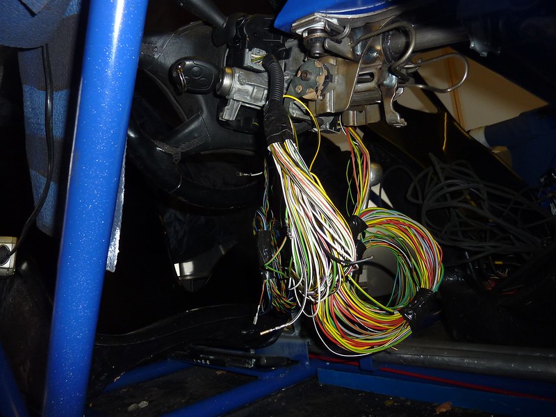 And, don't tell the wife, all the ones I extracted to date, everything that went to ECU directly got labelled  Left of shot is the Omex loom for a non-Ford rig that I bought, so once I figure out what each wire in each connector does, I'll begin to transplant the connectors from the Focus loom to the Omex. Only the injector plugs on the Omex loom are like-for-like, though the rest at least seem to have the same number of wires, by and large. Because the circuits were basically simple, I started to draw out the bits and bobs for the fuelling system, as there are now.  Oh yeah, nearly forgot about this! I have what appear to be *2* Inertia Switches. Going to post in technical section about this. 
|
|
|
|
Post by casesensitive on Sept 14, 2015 18:42:01 GMT
Did I buy the wrong donor?I did get a hold of a Focus / Zetec wiring diagram, which mercifully has specific pages for my 'Duratec ST'. Also, Big Wasa's thread on Focus Fanatics looks like it's going to be a big help. The wisdom of using my ST170 donor is starting to look a little questionable at this point. Aside from the Haynes manual not covering it explicitly, a cascading set of dependencies all spring from the change of ECU. The 19:40 train of thought is leaving the station, mind the gap. Retaining the stock ECU increases the risk of some pointless-in-a-lightweight sensor causing a warning or worse, a Limp Home situation. Replacing the stock ECU means changing a whole lot of other stuff. Returnless fuel system, Fuel Pump Driver Module. Most Zetecs pump fuel all the time from what I can gather, what it not used is returned to the fuel tank via a Fuel Pressure Regulator. I don't have either of these things. Instead, I have a FPDM, which tells the fuel pump whether or not more fuel is needed. If I go Omex, which I likely will, I'm going to need * to implement a return line * which means getting the fuel rail off another Focus (or destroying my existing one and tapping a fitting on) * to buy a Fuel Pressure Regulator * ditch the FPDM All of this is A Good Thing though, not keen on the ST170's interpretation of how fuelling should work anyway. ImmobiliserI imagine no ECU means no immobiliser, as they're coded to go together. My anti-theft measures are likely to include taking the ECU out whenever I leave it anywhere, so this is less of an issue for me than the insurance company, down the line. May try kiwicanfly's aftermarket solution. VVT controlI have the Omex 710, with a 600-series loom, modified with 1 extra wire that can allegedly control the VVT, but no one for 500 miles who knows how to tune it right. But, it will run without this, so I'll probably drop it into a proper expert on the other side of the water, in the same trip that it takes for its IVA. No biggie. Inlet Manifold Runner Control Now this is where it gets tough though, The ST170 has this trick inlet manifold that changes the air path to make it shorter at certain condition levels. Pulling it off means I have to replace it with motorbike ITBs. Now, I already have a set, and some beautiful DanST trumpets and backplate courtesy of the revolving door of induction upgrades, this one airforceone's. I need the FPR above here too, grand, but when he kindly offered me both 90mm and 50mm trumpets and filters, I declined, taking only the 90s. Which means cutting a great big lump out of my engine cover. Has anyone passed their IVA with chunks out of this? So, in summary, changing the ECU means going to IVA with air filter prarrie-doggin' it.
|
|
|
|
Post by casesensitive on Oct 25, 2015 23:56:30 GMT
Haven't updated this in a while, took a few weekends off to go watch the rugby, which hasn't gone well for anyone from about these parts really. What time I have spent I spent on wiring, or more specifically, stripping the focus loom back into individual wires and components; I have lots of these neat little piles knocking about the place. I've also all but completely run out of money, so I'm doing mostly jobs that don't involve buying new bits :-) Maybe Santa might bring me a custom exhaust?  |
|
|
|
Post by casesensitive on Nov 9, 2015 22:35:16 GMT
Centre ConsoleSo the wiring is one of those "it's so big I can't see the end of it" tasks, so I've taken a detour into something a bit more bite sized, the centre console. I picked up an used Koso RX2N from an abandoned build, and I set about mounting it in the centre, but orientated towards the driver, like in my 159. It's 40mm wider at the top than at the bottom because of the width of the Koso, which makes doing any sort of maths pretty much out of the question, it was all done by eye. I bought some A1 hard card from an art supply shop, damn hipsters, it was €3 a sheet. A really simple one to see if I could read it around the steering wheel without crashing the car. In the bonnet has worked for many, but I found that he screen was obscured at too many points of rotation by hands and bits of the stock wheel.  First draft with multiple pieces stuck together with masking tape, to see how the angled console might work. There's an issue at the cross member right hand side, so I figured I'd need to add 20mm 'tabs' to fold down to avoid a gap.   Take 3, now remade as a single piece of card. Far and away the most successful attempt of the day, hello false hope! Fit perfectly and needed only minor adjustments to be just right.  This is pretty much where it all started to go Pete Tong. Folding and cutting card is quite a bit easier than metal. The eagle-eyed amongst you will see my nope-start-again! error pretty quickly.  I used two manky bits of 8mm flats to manoeuvre the thing into my vice, the there end compressed with a G-clamp but I still had to quite a bit of it by hand/mallet  In the end, I let it go, the tabs once folded prevent you from bending any other part, I think I'd need a 3D anvil to get the job done properly. Making each piece separately, with tabs, and then joining them together is a possibility, and at least I have one good set of card templates, from which could potentially make new panels. This was the modelling process for how I'm going to make my Cover of Randomness, so this is an inauspicious start.
|
|
|
|
Post by James on Mar 15, 2016 12:09:44 GMT
I'm using the same ecu as you with a supercharger . I had a semi assembled loom and there is no wiring for a MAF . It uses throttle position sensor and anti stall valve . So I would have thought yours would have been the same .
|
|
|
|
Post by casesensitive on Mar 15, 2016 12:16:50 GMT
I'm using the same ecu as you with a supercharger . I had a semi assembled loom and there is no wiring for a MAF . It uses throttle position sensor and anti stall valve . So I would have thought yours would have been the same . Hmm, I guess I should be clear on this, I have a loom with a connector marked 'MAF'... which could be user error. |
|
|
|
Post by casesensitive on Mar 30, 2016 20:40:51 GMT
Wiring, I can’t put it off any longer. I took the 941 page Ford document, painstakingly selected the 321 pages I needed for the ST170-based Rocket, less things like door loom, air con etc, wrote them out in text editor. I then installed a PDF printer ( Cute PDF printer) so I could ‘print' the pages to PDFs. Print dialog box only allows 100 characters, so I had to do my document in 4 batches. Used a web-based pdf merging tool to make my 4 PDFs into one big one. I initially printed out the whole thing, single sided at home, passing the pages though the printer a second time to print page numbers (why Ford? Why?) on them, but I quickly realised that all those pages would never fit in the ring binder. Enter SWMBO. SWMBO excels at all things paper, so she took the merged pdf to work, printed it out in duplex, with centred page numbers, 321 pages became 161, and with the two of us stuffing the plastic sleeves on, we got done in a few minutes. She insisted we make an index, and use coloured dividers .. Not bad results, now I have a little light reading for the next few days. I’m at page 22.   |
|
|
|
Post by casesensitive on Apr 11, 2016 22:08:05 GMT
Wiring is going incredibly slowly, I took today off, SWMBO was away, so I had 3 clear days at it (and a few other bits) and I still got virtually nowhere. I did find a decent splicing and wiring binding trick though. Get some strong copper strands; I used the extra +ive battery terminal cable I had knocking around and removed the lining by The Big Red Wrench method. Stick the two or 5 wires to be joined together like you're mixing a deck of cards, twist, and then take 2 or 3 strands of your thick wire and tie it tightly around the wire bundle. Keeps it all together nicely while you solder.   Another top tip; solder paste is the buzz. Paint on the guey liquid paste, then heat with the soldering iron; instametal. Courtesy of my chinese tat suppliers. Definitely going to get more of this.  I did manage, after a lot of ruined attempts, how to use my crimper, and which of the 5 swappable jaws actually does the job. After a few runs I went with; strip wire paint with solder paste crimp connector melt solder bollo)( I forgot to put the shrink wrap on, start again!  |
|
|
|
Post by casesensitive on Apr 11, 2016 22:15:25 GMT
I finally fixed the ridiculous extended +ive wire, with its two SAE poles, one just flapping around. I have yet to do the -ive, as it has the main chase earth, but I will next week. Chassis, engine and battery all nicely connected. Isolator switch on the Ground pole, C-TEK quick-release charger connection on top.  I've no idea why, but the terminal pole on my isolator was far too narrow to seat neatly with any of the focus wiring, so I had to bodge it pretty hard. Looped copper strands around it and rammed them in with a small screwdriver, then tightened it all up, taking care not to let any cross to the other side of the isolator.  Using the Haynes manual mostly, but the Focus wiring manual was helpful too, I located as many '30s' (unfused permanently live) as I could and spliced them. Ran a line up to the future front fusebox (not bought yet!), but I'm a bit concerned it'll be a little thin at 2.1mm. My online calculator says it'll do 40amps for 5 feet before losing too much voltage, we'll see.  After all my exertions, I have precisely 1 completely wired fuse, 3 +ive only and half a wire to the ignition barrel position III (start). At this rate I should definitely be done before I retire.  Normally this late in the game, the budget goes out the window, but I'm scrimping and saving wherever I can, so I haven't bought any wire to make my loom with, I've literally stripped every wire from to the donor. That's a lot of loom tape, connectors, p-clips and more sticky black muck than I ever need to see. I organised them by thickness and put them into little bags, dozens of kilometres of it. |
|
|
|
Post by casesensitive on Apr 12, 2016 14:48:39 GMT
Chrome and shinyAfter a bit of hassle drilling through my chosen material of stainless steel, I managed to bend and drill 3 holes in this piece of ~5mm SS to make a nice bracket for my shiny new header tank. If you're doing this too, and also using the top bolt from the thermostat housing to hold it in place, put the bolt through the hole before you bend it closed..  The take offs all point in inconvenient directions, might be worth nicely asking the man to move them before ordering.  Steering column cover Steering column coverJust enough to stop the wiring getting caught mid corner. Salvaged from a crappy 'cold air' feed from my Puma.  Another rad outlet to blank, is there nothing a step drill bit can't do?  
|
|
|
|
Post by casesensitive on May 18, 2016 13:47:48 GMT
WiringBeen working away on the wiring a fair bit, the plan is to do a full write up once I have it all working, and I know it's accurate, so no by-the-minute updates yet. Essentially I've torn up the donor loom completely, stripping all connectors' wires back to the junction box, or where a pointless multi-plug connects to another. Using a cut down version of the Ford wiring diagram, with only the ~320 pages with info for the ST170, I selected which of the 2000+ connectors I needed to make the engine turn over and run as it would do 'stock'. I'm not having lights yet; walk then crawl. I then traced what each pin of those connectors went to, and recorded it in a spreadsheet. Anyway, here's the theory part, which is done for all connectors with 6 or fewer pins. The relays, fuses and grounds are WIP. The final write up will hopefully look a bit like this: Circuit: Injectors to ECUAll 4 injectors (Y108, Y109, Y110, Y111), Evaporative emmission (EVAP) canister vent valve (which I'm ditching), the idle speed control valve, and the Camshaft Timing actuator (VVT) all share a common switched +12v from Power hold Relay pin 5.  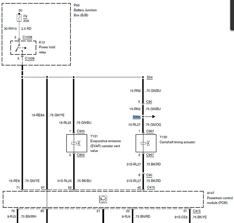 Injector wiring  The injectors each have a return straight to the ECU, though all of them are too short, so each was extended with the same colour wire from my bag of donor wires. The shared +12V Gn/Wh was also extended.  And for no better reason than because the multi-plug had 6 pins, another wire piggybacked.  Covered in convoluted tubing once I'd done a continuity check on each end 
|
|
|
|
Post by casesensitive on Jun 13, 2016 9:46:51 GMT
More wiring fun. Not much worth updating, but I did come across an interesting problem that'll likely affect anyone else stripping a donor loom and having a go themselves. The PATS / Immobiliser connector C390 varies in shape, colour and wire colour based on the year of manufacture, and this is not reflected in the wiring diagram at all! So, according to the Ford wiring diagram, the connector should have 4 female pins, with 5 wires: p1 (Gn/Bk x 2) p2 (Bk/Ye) p3 (Gy/Ye) p4 (Wh/Gn) 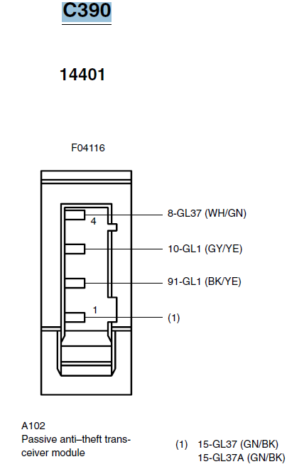 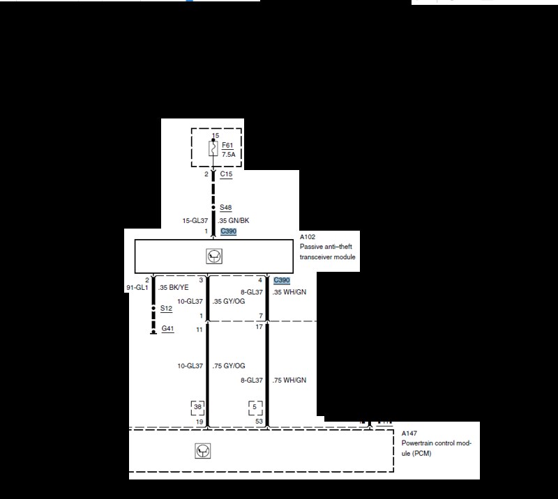 Big Wasa's ST170-how-to Big Wasa's ST170-how-to clearly shows a green connector like this one, but with 4 black wires, and he warns that yours may not look like this. 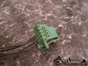 Well, mine is nothing like that at all! 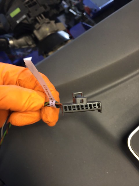 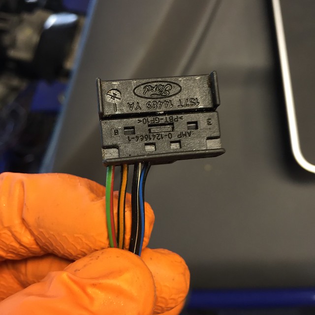 Believe me, I tore the bag'o'wires to bits looking for one that matched the manual, it isn't there. This is where my odd-looking connector came from, right under the barrel and attached to the PATS sensor ring. 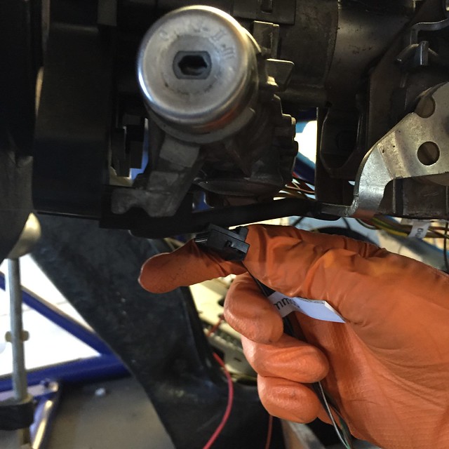 This is my 8-pin female connector with 4 wires, which I've guessed is the same orientation, based on the colours for p1, p2 being about the same (fused +12v is usually some variety of green with trace, grounds black/black with trace) p1 (Gn/Rd) p2 (Bk/Og) p3 (Bk/Wh) p4 (Bk/Bu)  However, what concerns me slightly is that the Gn/Rd and Bk/Og are twisted tightly enough it can't be an accident, which in network cabling is a method of reducing interference. Why would you need to protect against interference on the power cables and not the data connections? The other two may simply be twisted at a different, much less frequent rate, and have become decoupled over the last 2.5 years though. The other two go back to the ECU, so one of them carrying the wrong type of signal will at best confuse it. 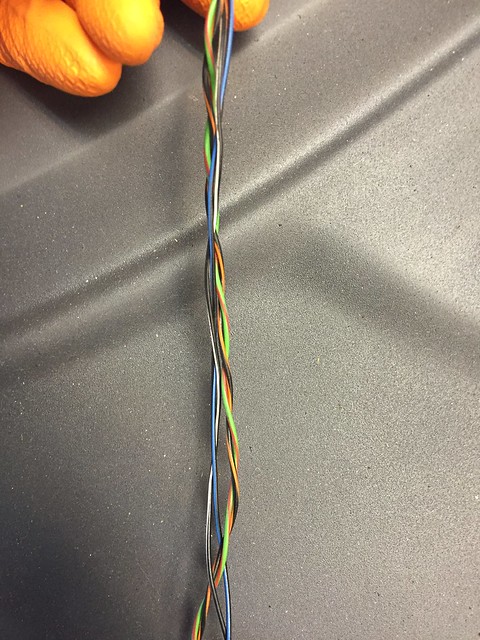 |
|
|
|
Post by casesensitive on Jun 19, 2016 22:10:46 GMT
Getting there. Today I finished the wiring for: MAF VSS Fuel Pump Driver Module Inertial Fuel Shut off Fuel Sender Which ranks as far and away the most productive day of wiring so far. Just the IMRC and the two cats to wire in and I can think about turning it over. No trunking or convoluted tubing yet, and some of these will need a trim. Theoretically, the fuel system is wired up, so I could put some fuel through it for the first time in 2 years. Got to put some wet stuff in, and put something between exhaust and the powder but could conceivably cough into life by next week. We'll see. Got a nice-ish 7 wire staggered splice, all the ECU grounds and a few returns.  |
|


