|
|
Post by casesensitive on Jul 30, 2016 23:13:04 GMT
Got a PATS transducer ring and wiring connector from a local scrappy  drove it home impatiently, wired it up and turned the key. Good news, the electronics fired, the coil pack lit up the noid light, as did Injector in number 1 cylinder. Bad news, the fuel pump is knackered, more on that in the next post. Trunked the engine-view of the wiring up nicely, now back to looking very like before I stripped it, except now the other ends all have nice push-fit connectors and labels on.  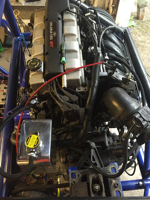 |
|
|
|
Post by casesensitive on Jul 30, 2016 23:32:37 GMT
I've had a bit of a think about the fuel sender.
With my HibirnoKiwi fixing plate in the bottom of the tank, I don't need the threaded bar to extend the sender, the base will rotate nicely into the tank plate, the wires and pipes will 'float' and the top will attach to the top of the tank.
I'll probably extend and bend the float backwards; calibrate for my Koso dash before sealing up the tank, I was going to spend £43 on the Spyda electronic gizmo, but when a mechanical hack works just as well, why bother? If it all goes wrong, I'll have my modified fuel level gauge to fall back on anyway, just swap out the wiring.
Wired up the Koso dash to the perm live and ground for fun yesterday, the dash does this brilliant little start up routine light show, I think I'll wire it in with no data connections just for the sense of theatre.
|
|
|
|
Post by casesensitive on Aug 28, 2016 14:09:00 GMT
Short weekend this week, on a short leash. Spent much of it tidying up wiring I won't need, including abandoning the stock instrument cluster and aux instrument cluster completely, which did away with dozens of wires. Battery connectionsMy battery connections were a holy show, and I've wired F20 (ECU) permanently live so that it retains the idle config when the isolator is off. I've covered the positive terminal in clear sealant in case of accidental shorts, which have been happening a good bit. Having a battery box/cage that's metal isn't brilliant for this. I left this at home, so everything is still stacked.  Front fuse board mounting plate Front fuse board mounting plate
I drilled 8mm holes where the pedal box bolts are, and made up 55 and 45mm long M8s that'll fit exactly right, when I locate the unused spacer bar I seem to have misplaced. The steering column end is nothing posher than tapped M5 holes.  |
|
|
|
Post by casesensitive on Oct 17, 2016 12:35:04 GMT
My plan was always to wire up the car any-old-way, check that it still works, and that I can keep it fueled etc. Which I did, but the problem was, that was a terrible plan. Don't be like me kids. Now that I finally got it fired up and, once the ECU-keep-alive direct feed is in (thanks mawdo81), running somewhat smoothly (still a very high idle and a little lumpy, but there's no exhaust manifold, exhaust or O2 sensors, so not bad considering); I now needed to rip it to bits and make it tidy again. Basically, my engine wiring (I have no lights in yet) looks like this, except it's all currently wedged in between the top-most cross member and the rear firewall.  So this weekend and last I set about the onerous task of cutting feet of extra wire out of my working loom. Which will most likely result in it not working anymore. It's such a rat's super-hive it's hard to know where to start, but after I boxed the ECU up and stuck that to the battery tray, I had an idea where it was all going to go. I mounted the fuse and relay boxes up on the back of the firewall (twice, height wrong the first time), and moved the main chassis earth back inside the engine bay. Cutting my many-grounds-become-one mess of copper and solder was harrowing; though as with everything in this gig, the second attempt was much better. Joining 12-15 wires in one junction, with shrink wrap, is nearly impossible, so I took to merging 3/4 similar gauge wires with 1 larger gauge wire going the other way, and cutting that short. Shrink wrapping is nice, and then when I have a few of these, I'll join the 4 of those to the battery/chassis earth line, much neater, and if I need to move or add one, it's fewer out-of-action circuits. I'll do the same with the other big multi-way splice, the Power Hold Relay output, and hopefully the rats super-hive will be more like a family nest. Still, I reckon I'll be covering the whole lot up, don't really want anyone seeing it :-O On that, I didn't order the Cover of Randomness back in 2013, and getting one now, even if it were a good idea would be tough; is there anything in the IVA about Fuel cover having a flap or door? Obviously I need to be able to change a fuse or reseat a wire, but if I enclose the area behind the passenger in a single box, the fuel 'compartment' would have an opening to outside/passenger cell in it. Will I need 1 box for the fuel tank and a sub box for the mingin' wiring? |
|
|
|
Post by casesensitive on Oct 22, 2016 21:58:58 GMT
Last couple of weeks have been spent shortening and tidying wires that should have probably been measured properly to start with. The ecu and battery boxed were joined, lined with heat-reflecting radiator backing made mostly of polystyrene which should have vibration-dampening properties.  There was much snipping and re-soldering, thankfully, I've gotten a lot faster, and the splices a little better planned. 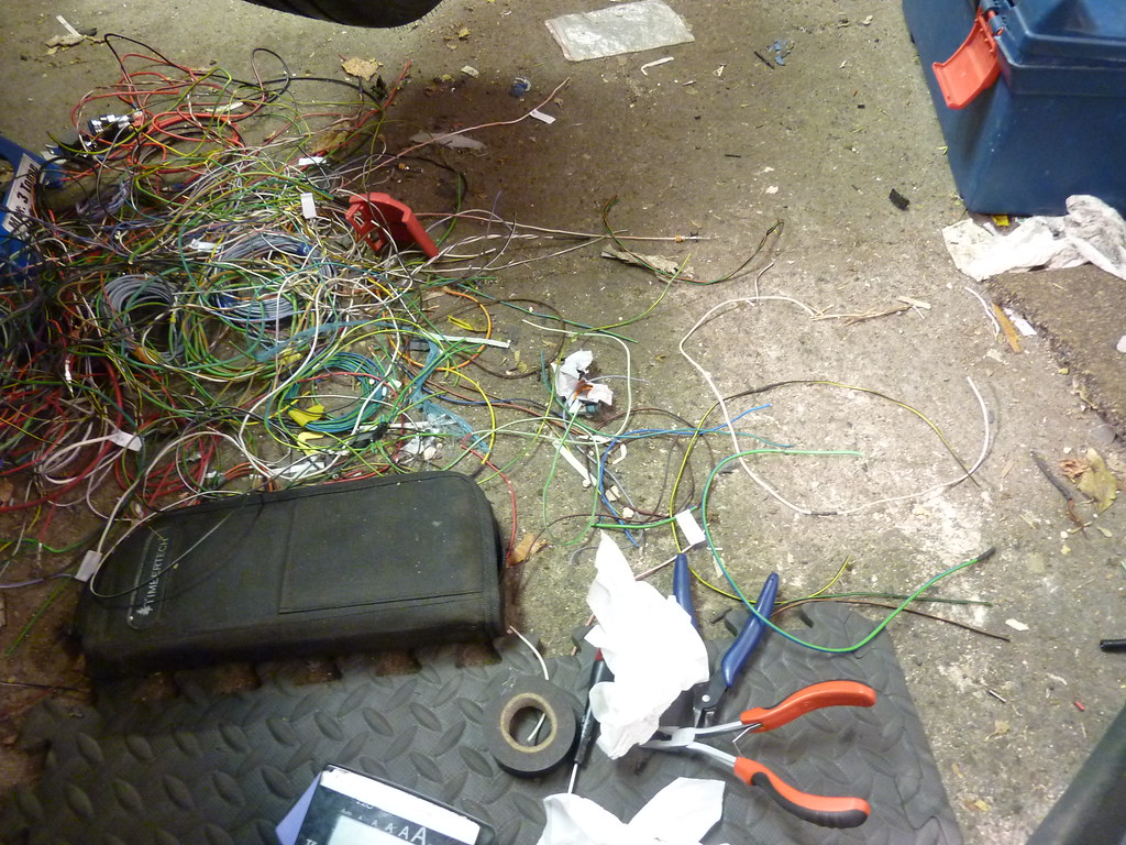 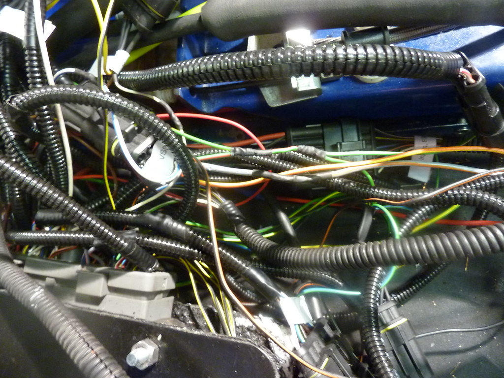 Fuse and relay boxes mounted to the rear firewall with some cut-down rawlplugs filling out the holes  Inertia cut-off switch  Still the ground lines to do, and some of the 6-way ones to shorten, but getting there, and now the engine wiring takes up a smaller floor area. 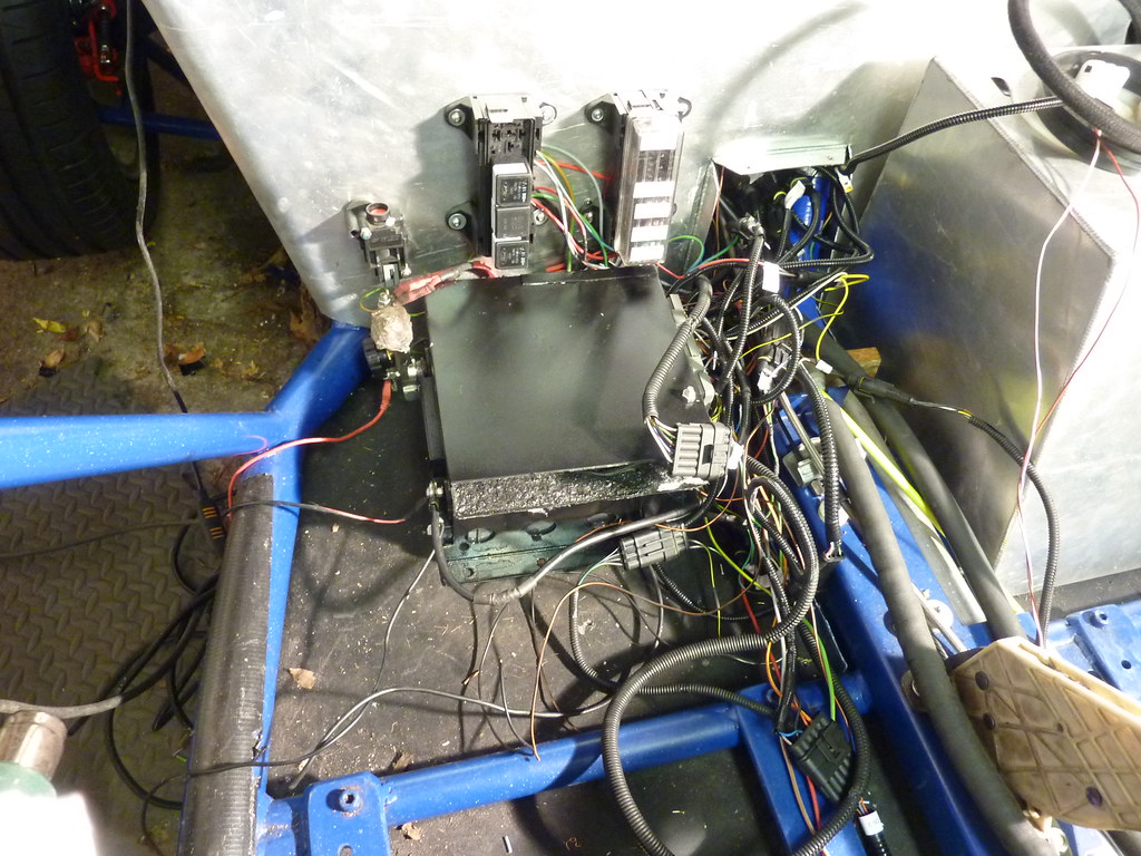 |
|
|
|
Post by casesensitive on Nov 6, 2016 22:04:40 GMT
Neutered the clogging filter on the fuel pump after some issues, pumping freely after.  After a few few wiring snags getting started again; V33 diode in backwards, nice one, and the FPDM ecu 54 connection popping out, she sparked back into life. But very lumpy. Took a video of the exhaust while it was running, clearly number 4 isn't burning. After 20 seconds exhaust port was cold and a bit wet with fuel. Stuck my noid light on the coil pack plug and injectors 1 and 4, confirmed everything was electrically sound. Swapping the HT leads from 2 to 4  and turning it over again, this time the silence moved to cylinder 2, and 4 while overfuelled, was firing. I should really have just tested stuff, but I'm losing patience, so I ordered a mack-daddy Magnecor HT leads. And not because it's broken, but an OE coil pack was cheap at €30, so I ordered one of those too. |
|
|
|
Post by dgibson on Nov 7, 2016 2:04:07 GMT
Coming together nicely. Shortening up the wiring is always a a pain. I have chassis/frame earth at both ends of the car, AND have a good size earth running with the wiring harness from front to back.
|
|
|
|
Post by casesensitive on Jan 15, 2017 12:26:53 GMT
Finally, because I'm a glutton for punishment, and spending 8 months or so wiring the car once wasn't enough for me, I'm starting again. I think this might be the first Rocket or even MEV to use the Motorsport Electronics ME221? 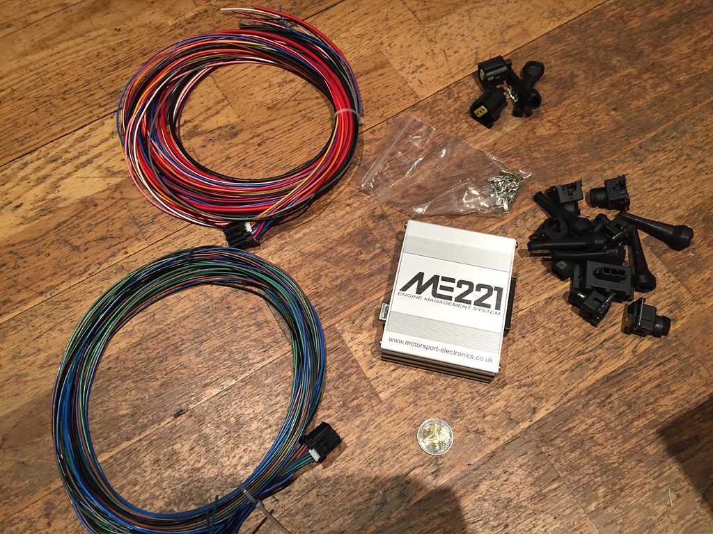 First, it's TINY. That's a €2 coin, which is about the same diameter, give or take as your £2 coin. It fits inside my hand. It's purpose-built to map the VVT in the ST170 progressively, rather than a simple on and off as Omex, Megasquirt and others. Their PnP version looked really handy, but the runs of the cables is too short, so I opted for the wire-in version, so I could get the wiring runs just so. I won't be repeating my idiotic decision to have multi-plugs at the ECU end for each wire either. I bought wire-piercing probe leads for my multi-meter instead, going ECU straight to the connector. Interestingly, there are no plugs for any of these, so my loom is going to get MUCH lighter and less complicated: FPDM Fuel Pressure Transducer Sensor IMRC Knock sensor MAF Sensor (!) Vehicle Speed Sensor Post-Cat O2 Barometric Absolute Pressure Sensor PATS Immobilser ODBII Alternator It's only in writing out the list of what it doesn't support that I realise I won't have any OBD  to connect my UltraGauge to, but I will have a serial port which I can connect a laptop to to get all the stuff out of, including datalogging if I want to. There are 104 pins on the Ford ECU, 53 of which I had wired up. This has 28 wires, and that's it. ME are almost finished their wideband AFR O2 gauge and controller, so I'll be able to tune this bad boy on a rolling road myself (it's got an AutoTune function) Plan has always been to go Ford stock wiring, butchered, with stock ST170 bits custom ECU with as standard bits as it supports (no immobiliser etc) custom ECU with lovely motorbike bits So far I've collected up GSXR1000 ITBs, jake's ST170 stub manifold is on the way, airforceone's DanST trumpets, backplate and sausage filter, fleaBay Focus 2.0 fuel rail with return, standard focus fuel pump with return line, Venhill throttle cable kit. I'll space up the ITBs and get it all built up before I start the swap over. Big fun. |
|
|
|
Post by casesensitive on Feb 27, 2017 10:38:57 GMT
Rip it all outHaving recently completed wiring up the stock Focus bits, it's time to rip it all out. I picked up an ME221 with wire-in loom, and I've done quite a bit of the prep work to calibrate sensors etc. First, get rid of things that it doesn't support or need. O2 SensorsThere's only 1 cat sensor port, so the post-cat sensor got bunged. £1.50.  Fuel rail Fuel railThe ST170 fuel system is more modern, being returnless, with a fuel pressure transducer sensor and Fuel Pump Driver module. I picked up a fuel rail, fittings and fuel pump (with return line, 'lid;) from a regular 2.0. It was manky, so I went over with a wire brush and sandpaper.  Adding the ST170 injectors (315cc v 200cc) using the clips from the 2.0. Brucy bonus, the regular one has a schrader valve for measuring fuel pressure. I actually bought a fuel pressure regulator, that is Blue And Shiny but it has push fittings and I haven't figured out how to amalgamate it onto my fuel rail.  One for later, for now, the 2.0 one (3.8bar) will do fine).   Temp fitting here, reusing vacuum lines from MAF to fuel pressure regulator, bunging the T with an M6 bolt.  Ran another length of fuel hose back towards the tank from the return end 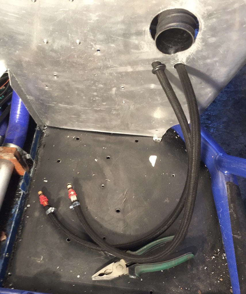
|
|
|
|
Post by casesensitive on Feb 27, 2017 10:45:16 GMT
Goodbye Ford wiring! Removed the IMRC, FPDP, Immobiliser, Barometric sensor, Alternator plug, 1 O2 sensor, and all that minging temporary wiring.  Leaving me with just my fuses and relays  And the ME221 to go in  Only got the power wired in as I spent a few hours repairing the bodywork on the daily driver. Next weekend will see the first of the permanent wires get laid down. Rotated and flipped battery to give me an other inch or two behind driver seat for seat adjustment too, but phone died before I could capture the evidence. Will have to make certain that no water gets into that section, because battery terminals are now 1cm from the floor. Will likely drill some drainage holes this side too. |
|
|
|
Post by casesensitive on Mar 12, 2017 16:45:50 GMT
My Intake Air Temperature sensor arrived, not a Bosch one, with its well-known values and that's where today's adventures lead us, with some maths! The Intermotor part number is 55716, same M12x1.5 threaded air temp sensor. same 2-pin mini-timer connector, looks visually similar, but with different characteristics to the Bosch one sadly. It is also a negative coefficient thermister sensor, that is to say resistance decreases exponentially with temperature. Good. A google search shows that this is the same Part number and application as FAE 33166, which is what's stamped on the part itself. FAE are slightly more forthcoming about the way in which their parts work, giving the actual formula for calculating the resistance at a given temperature, given a few more things. www.fae.es/files/product/pdf/familia-33-bq-50.pdfNow, sadly, it involves some reasonable heavy maths.  Also, we don't know what the Resistance at 25 degree is, nor do we know what B, the constant is. The great thing about constants (like the C in E=MC^2), is that it doesn't vary, so we can effectively replace it with a fixed value and then manipulate it to suit our observations. So, assumption time; the temperature in this room is 25 degrees, maybe, I'll get an air thermometer and check this. I measure the resistance in air temperature, and find it to be 4390 ohms. I then let the oven get up to 50, stick the sensor in there for 30 seconds, and measure resistance. I repeat this at 100, and by sticking it in the fridge at 5. This gives me some values to test, and to extrapolate the constant, B. =SUM(H1*EXP((3300*(1/(A2+273.15)-(1/(25+273.15)))))) I wasn't about to do all that work myself, so I stuck the what we did know into a spreadsheet. I've shared this to anyone here: docs.google.com/spreadsheets/d/1bjRe4pdIHAm9kDZrqpFEHwFIypiJcXsr0BlkHAP22Xs/edit?usp=sharingThen I taped the two receptors to my IAT, which was attached more securely to the multimeter prongs using the female pins that came with my DIY loom kit.  What I learned from this exercise is that you can only really rely on steady temperatures. Room temp, sure, the 15 degrees the fridge gets to? Yep. The -5 the freezer bottoms out at? Also yes. I thought I'd be clever and just photograph the two instruments every few seconds as another value appeared, in the fridge, freezer and the oven. The issue is that while the IAT resistance changed, and in the right direction, it took a good long time to settle on a number, so most of the 'on-the-way' values I have are gibberish. I'll have to concoct a system for creating conditions for temps to hold for a full minute to get accurate values. I reckon I'll have to wait for the wife to go out before I commandeer the oven. Putting the values I painstakingly made into the MEITE, I sort of neglected to check how many you can have (16), so I really should have picked my target values around the range of temps I'd expect to see in real use. For the Air temp, I could only generate and hold a few discreet values between; This are my observed values 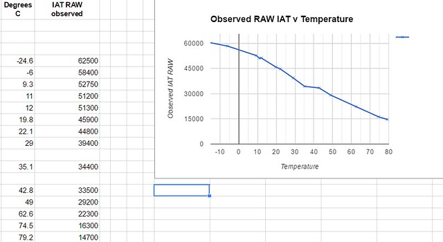 but I 'smoothed' them in MEITE by dragging 2 wonky datapoints closer to where the curve/line says they should have been  For the sake of the wider community, though I don't actually need this long term, I calibrated the IAT component of the Ford MAF too. Ford IAT from the MAFWiring pins 1 (orange, ME221p19 and 6 (black, ME221p28 sensor ground) on the stock MAF gives you the IAT component. 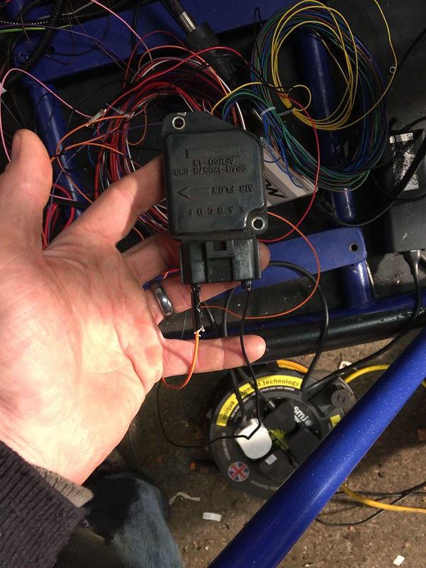 . Repeated the same tests I'd run with the Intermotor one; on the floor, on the rad, outside, fridge, both freezers, and then the oven for a few temps, I got this slightly sloppy graph, but the data points were pretty consistent. The granularity, linearity (and accuracy, in all likehood) fall off a cliff under 25 degrees C. I took these readings a few times to be sure. docs.google.com/spreadsheets/d/1bjRe4pdIHAm9kDZrqpFEHwFIypiJcXsr0BlkHAP22Xs/edit?usp=sharing To be honest, the MAF is original (2002), so it's properties are possibly degraded. It takes a long while to settle on a particular RAW value, and still oscillates about 300 RAW points or so. Intermotor one settled faster and was +-50 RAW at a thermocouple-fixed temp. I'll be happy enough to ditch the MAF and move to the GSXR ITBs, and I'll drill the backplate to accommodate the standalone IAT. |
|
|
|
Post by casesensitive on Mar 12, 2017 16:48:11 GMT
Ford TPSTemporarily wiring up the stock TPS (purple (TPS), pink (+5v), black(sens gnd)), I took readings for completely closed (10900) and fully open (61400) which are pretty close to the basemap high and low values. There were also some mental figures in the basemap that must be mistakes, 367.280457% on line 18984?  I measured the length of the arc the restrictor on the butterfly makes, and moving it to roughly halfway, I confirmed that my 50% was about halfway through the TPS RAW values. It's not accurate enough to take a detailed reading, I just wanted to be sure that the graph is roughly linear, which it should be, the TPS is essentially a big potentiometer.  Plotting these two values into MEITE and everything else to 65535 / 100, I got a nice straight line graph, and oscillating the butterfly by hand I found it followed the line pretty well. It's worth mentioning that I got these values by manually rotating the TB, the way my venhill cable pulls through the stock Ford bracket, I don't think I could actually get WOT. Hmmm. I'll be using GSXR TPS when they go on anway, but it's interesting to note I'd never have had full power out of the arrangement I had put in. Part of the challenge of not having a build buddy, no one to stand on the loud pedal while I make sure it opens the butterfly all the way :/
|
|
|
|
Post by casesensitive on Mar 12, 2017 16:50:58 GMT
Wiring for real I reused as much of the electrics from my Ford setup as I could, no sense in redoing all those relays if I didn't need to. The previous permanently live feed to keep the Ford ECU's memory fed had it's 10A fuse replaced with a 5, two grounds (p9, p11) temporarily connected to earth and we were up and running. As usual, everything planned in the spreadsheet in advance, mostly needed to confirm the polarity of various bits and bobs from the Ford wiring diagrams. First up, cam and crank sensors, as they don't need external power. I ran the 2.5m unterminated wires through the hole in the tunnel, up past the cooling set up to where they live, and then snipped 2-3 cm longer than I needed.  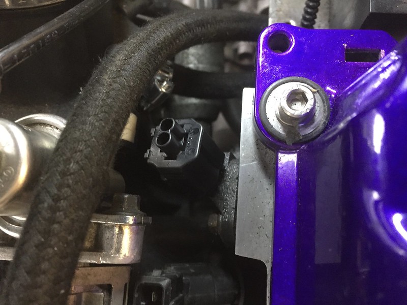 In each case, make sure the terminals/pins and the connector fit the component you're wiring before you start. I very nearly wasted one connecting to my coolant temperate sensor up, which of course doesn't match any of the supplied connectors, you have to reuse the Ford ST170 one. Slip on the boot, expose 15mm or so of each wire, tin with liquid solder (magical stuff), crimp on the connectors. melt solder, push into the connector, pull up the pants, push in the yellow retainer. Went reasonably quickly compared to the length of time it took me to do the Ford bodge.     |
|
|
|
Post by casesensitive on Mar 12, 2017 16:51:26 GMT
For the ones that needed +12V or +5V lines, I attached a length of 11A wire from a 30m spool, traced out the distance of both, and snipped; giving me a red line exactly as long as the sensor/driver wire. So while I've got lots of the connectors wired up, there's no power to any of them as yet. I regret not buying brown wire for sensor return (ECUp28) lines instead of using black, which should really only be battery or chassis earth. Equally, a different colour for +5 and +12v would have been great. The Ford wiring scheme is actually very elegant, reds are 'neat' +12V all relayed +12v lines are some flavour of green, sensor returns are brown, chassis and earth grounds are black/black with trace. A couple of bits need some working out, for instance, how to wire up a 4 pin O2 sensor from the Ford wiring with a single O2 sensor wire on the ME221. The fuel system is another one that is pretty different on ME221, so here's my plan for that:  Progress so far:  It was at this point I realised I have come to be without enough connectors. I can't imagine I was supplied with too few, so they must have fallen out of the box I was keeping them in. I've emailed ME to send out some replacements. Play was halted there on wiring day 1. Critically, I was able to display CAM and CRANK IRQs as well as RPM (~190) in the MEITE when I turned over the starter motor, so I'm getting a signal from the sensors. |
|
|
|
Post by casesensitive on Mar 22, 2017 9:14:53 GMT
As my fuel pump failed a while back, and I replaced it with an item from a standard 2.0 focus, I had to redo my gauge extender. Neater job this time with shrink wrap over the copper wire. Was very careful to make sure it was at exactly 0 when touching the bottom of the tank, and full when right at the top. 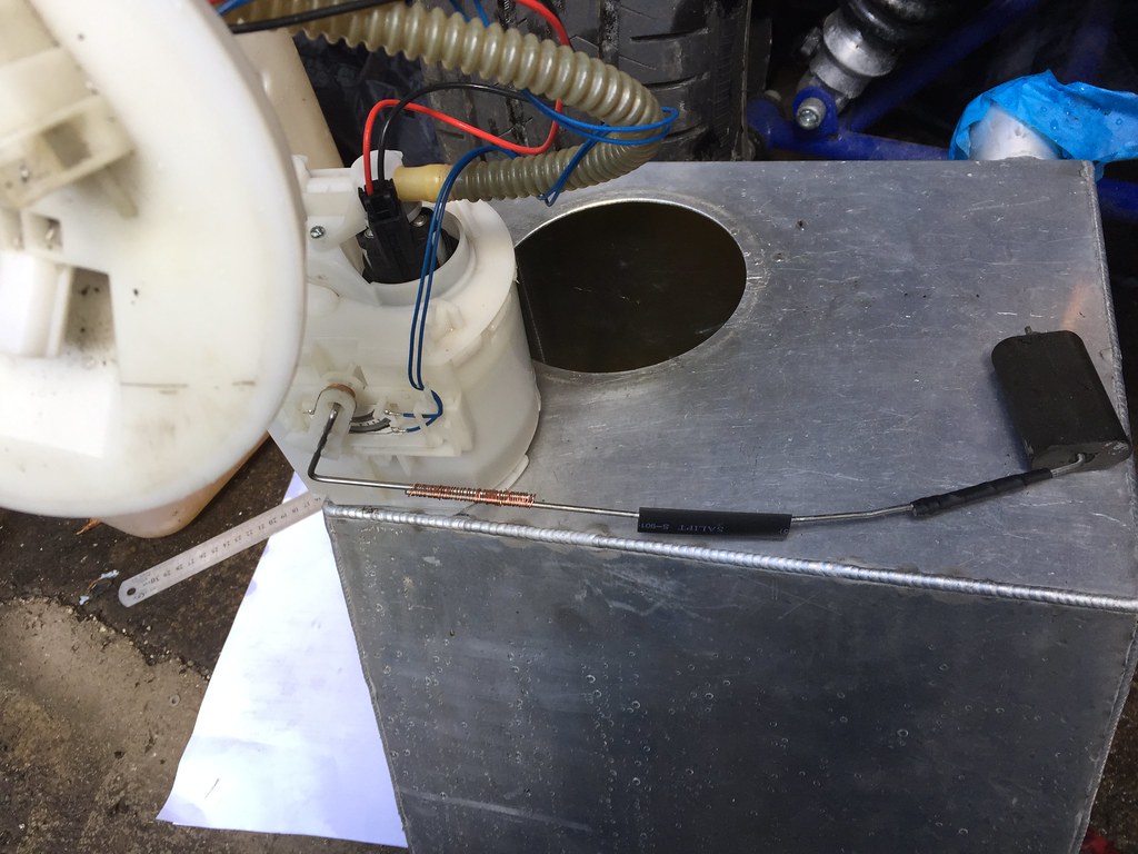 Sender sealing not permanent fix :-)  Re-routed my fuel system wiring according to my scribble, connecting the ME221 fuel driver line to pin 1 on the Fuel Pump relay. On start up, the ECU didn't give the 2 second prime and actually didn't pump fuel either. Hmmm. Wiring the inertial fuel shutoff switch to +12v kicked the pump into life alright, sending fuel everywhere! Turned out the grommets inside the fuel connectors had perished over time, and left a gap. Put a new one in and we had a nice steady stream from in, through the fuel rail, and back to the tank at 380kpa. Result. |
|