|
|
Post by davej98002 on Feb 4, 2017 19:27:36 GMT
Not trying to argue here, just my opinion based on what I have found in some past racecar builds. If you take a 3/4 inch (19mm) copper pipe 10 foot long, then twice for going forward and back, you have added over 1/2 gallon of fluid volume. This copper pipe will dissipate a lot of heat to the free air if allowed. Routing it thru the cockpit and insulating it so that heat does not affect the riders will lower that heat loss some so routing it to the outside somehow is needed. We found that using an infrared probe clamp that we lost about 20 degrees F between the engine in the rear and the radiators inlet then another 8 degrees from the radiators outlet and the engine on the return. Biggest loss was in the radiator and the lower over all temp dropped from 215F down to 150F. The 195 degree F thermostat was closing, opening, closing... SURGE. Roger is adding a surge tank and this was what we had to do also. Where I would spend most of my cooling mods would be in OIL cooling. Replace the small factory cooler with a remote mounted larger unit, with a temperature by-pass adapter so oil will reroute back to the engine only when cold. That oil cooler should have a relay switched on fan to pull air thru it when at slow forward speeds or when stopped in traffic. That car we built was a salvaged 1968 Porsche 911 that we put a large front wheel drive V8 in the back. So cooling was a big engineering issue going from a air cooled 2L H6 to a water cooled 7L (425 ci) V8. That mid-engine mounted V8 took up all the back seat and cargo area. This was when a crashed 911 was worth about $30 in scrap.  |
|
|
|
Post by roger32849 on Feb 4, 2017 21:10:40 GMT
The actual extra volume would be 188 ounces calculating 20 feet of extra length using 1 inch tubing. There are 231 cubic inches in a gallon of water. This means about 3/4 of a gallon of extra coolant. There is a difference cooling a mass of liquid contained in a vessel vs cooling the same volume through a pipe. The OEM radiator and oil cooler should take care of the this engines requirements.
I will keep this entry bookmarked for future reference.
Thanks Dave
Roger
Worcester, Massachusetts
|
|
|
|
Post by roger32849 on Feb 4, 2017 21:20:28 GMT
I will throw this out there. Has anyone had any luck using a bender on aluminum tubing. The bender I have in mine is sometimes called a Hickey Bender, used to bend EMT commonly called conduit. I didn't know if the tubing would kink or crush if I tried to bend it. I want to do away with some of the radiator line splices and hoses by custom bending the aluminum to meet with the radiator and engine inlets and outlets.
The other question that was pitched by a friend was to look into using soldered copper lines instead of aluminum and adding the fittings and elbows as necessary. I am not sure copper is the answer, but just do not know why. I would be afraid the soldered joints would work loose or split. Anybody have any thoughts on this.
Roger
Worcester, Massachusetts
|
|
|
|
Post by davej98002 on Feb 4, 2017 22:51:21 GMT
On copper tubing, using a high tin/low lead alloy solder is good to about 230 Degrees at 15 PSI. But if you step to a brass based BRAISING rod it is good for about 500 Degrees @ 200 PSI. Silicone lined brackets should isolate it from movement. But these are ratings at about the 100% factor for use in low pressure STEAM boiler plants, so 215 Deg F and 18 PSI should be OK outside the cockpit safely. Its been over 25 years since I dealt with steam heat systems.
On bending the aluminum, look up annealing process for aluminum. I would anneal it, pack damp sand in it, bend it and then clean the sand out. It will age harden in a day or so.
|
|
|
|
Post by roger32849 on Feb 6, 2017 0:17:14 GMT
Surge tank in place on the right side of the TR1ke 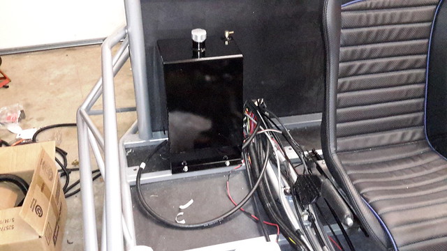 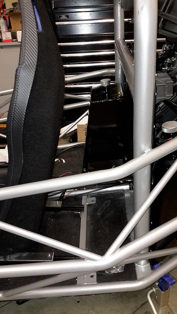 I finally got off the fence and called Dove Racing LLC. The surge tank that came as an option when I originally bought the kit contains the OEM fuel pump. It mounts on the right side behind the seat. I spoke to Peter Dove and gave him the measurements needed to have another tank made. Once I remove the two saddle tanks in the engine bay and install the new tank behind the left seat my fuel capacity will be 7.8 US gallons. Currently it is 8.1 US gallons, a loss of 3/10 of a gallon or about 30 US ounces. The overall design of the TR1ke provides enough leg space for me, the seat and fuel tank. I am 6 feet tall so I am not short nor am I Andre the Giant either. Once installed I will have enough fuel to drive about 200 miles if I get 30 MPG. I am hopeful for better mileage, but we will see. I hate it that I had my fuel tanks powder coated, and modified to accept an in tank roll over vent safety. It represents a bit of money spent that I am not going to put to use on this project. However, the safety factor in getting the fuel tanks out of the engine bay and in front of the bulkhead is a solid move and is worth the cost of keeping me from becoming a statistic. Everyone should read the sticky note warning concerning the fuel tanks and the front suspension. Roger Worcester, Massachusetts |
|
|
|
Post by roger32849 on Feb 6, 2017 12:48:43 GMT
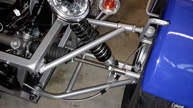  I am asking about the NEW vs OLD suspension A arms. This is what I have. How do I tell if it is the old suspension or the new and improved? If anybody can tell me, it would be great to know. Roger Worcester, Massachusetts |
|
|
|
Post by Stiggy on Feb 6, 2017 14:25:11 GMT
I will throw this out there. Has anyone had any luck using a bender on aluminum tubing. The bender I have in mine is sometimes called a Hickey Bender, used to bend EMT commonly called conduit. I didn't know if the tubing would kink or crush if I tried to bend it. I want to do away with some of the radiator line splices and hoses by custom bending the aluminum to meet with the radiator and engine inlets and outlets. The other question that was pitched by a friend was to look into using soldered copper lines instead of aluminum and adding the fittings and elbows as necessary. I am not sure copper is the answer, but just do not know why. I would be afraid the soldered joints would work loose or split. Anybody have any thoughts on this. Roger Worcester, Massachusetts It is possible to get a 90 deg bend with a simple compression bender. It does start to flatten the tube as you can see but I the section surface area is the same so no restriction offered. A fixed radius bender with a follower would be better. I have a spec sheet for the tube if you need it. |
|
|
|
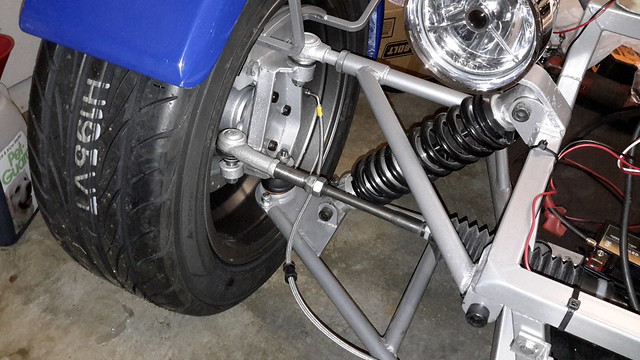
Post by Stiggy on Feb 6, 2017 14:33:55 GMT
I am asking about the NEW vs OLD suspension A arms. This is what I have. How do I tell if it is the old suspension or the new and improved? If anybody can tell me, it would be great to know. Roger Worcester, Massachusetts The lower bones on the prototype were Rocket but upside down, track width was not wide enough. I suggested RTR look at widening and I think they added 40mm. No idea why yours have bends in the tubes, I notice that some have bends in the top bone too. You can tell if you have wider ones if you look at the position of the lower shock mount, if this is at the edge of the ball joint plate (as yours is) then I suspect it is the longer bone. It would be interesting to hear what you track width is. I notice you have the fabricated uprights with Focus stub axles. Adding the stub axle to the plate upright makes them very heavy but they increase track width beyond the Cortina geometry, as used in the alloy rally design alternative. |
|
|
|
Post by roger32849 on Feb 7, 2017 13:27:54 GMT
I have been holding this back, but about a month ago, I was installing the dual exhaust "Y" pipe and while lifting the swing arm with rear shock disconnected, a coil became lodged in swing arm and broke a sizable chunk of the swing arm. I found a NICE replacement on ebay and after removing the bearings and cleaning it up, I delivered it to my (not so local) powder coating company. I opted to do a little something different and have it coated with a "chrome luster". When I bought the replacement swing arm, it came complete with an aftermarket aluminum R1 chain guard with the R1 logo cut out. It is also getting the chrome luster treatment. In addition to those items my front turn signal mounts and the rear fender anchor are all getting the same sort of process. The photo shows the damage. It also shows the extra heavy duty real coil spring responsible for the damage. It probably would not affect performance, but it simply looks bad. All things considered it was a minor setback and I have ordered new bearings and caps. The center tube is okay.  |
|
|
|
Post by Stiggy on Feb 8, 2017 11:23:05 GMT
Hi Roger, did you see my question re your track width? This information is important for me to gather if we are to able able to advise the most appropriate set up. Please answer.
|
|
|
|
Post by roger32849 on Feb 8, 2017 12:30:59 GMT
Stuart:
My track width measured between the mounting flanges of the hubs with rotors installed is 66.5 inches. Measured at the outer edge of the tires it is 70 inches. Center tread to center tread is 63.5 inches. I have 15X7 Konig wheels with a 38mm offset. As an added piece of information, I have yet to do a front end alignment except to get the tires close. Measurements above were taken as close to the center of the hub as possible.
Roger
Worcester, Massachusetts
|
|
|
|
Post by Stiggy on Feb 8, 2017 13:30:28 GMT
excellent, thanks, my original calcs and C.O.M guesstimates were based on 1600 mm track width and 2600 mm wheel base, yours is close to that. It is quite possible that the alloy upright option is narrower than the Ford Focus rear stub axle bolted to the fabricated uprights.
I never has the opportunity to measure or weigh a finished tR1ke. It would be interesting to know the corner weights and approximate COG with an assumed drive and passenger on board of say 80kg each. I would like to think the COM would be half way down the wheel base and no more than 500 mm above ground. Maybe I will never know. One wheel at a time on bathroom scales would provide some of the missing info. 380kg empty?
|
|
|
|
Post by roger32849 on Feb 8, 2017 15:03:21 GMT
Currently my trike is on jackstands. I can do the corner weights after installing the new swing arm. It should be ready by Friday (earliest) or next Monday (latest). I will install it as soon as it is ready. I will use some ballast in the seating area... per your recommendation.
Roger
Worcester, Massachusetts
|
|
|
|
Post by roger32849 on Feb 9, 2017 18:43:57 GMT
I just had a conversation with Peter Dove of Dove Racing LLC. He is the designer of my 3.9 US gallon fuel surge tank. He has the design plans for several other tanks that incorporate the internal OEM Yamaha R1 fuel pump. I asked him if he could have a tank made to fit behind the left seat without a fuel pump. He is currently having that done. He has not been available for the last week or so, but has returned home and will be able to design and build the tank for me. I did not seek any fabrication work here locally. Not to many companies do this sort of work on an individual basis. They will want to make 10 to 20 and not just one. I have to mention that the custom tank is not available except through Dove Racing LLC. It is not an Exo Sports Cars product. This is simply one of many custom made accessories that DRL provides.
Roger
Worcester, Massachusetts
|
|
|
|
Post by smokinguitarplayer on Feb 11, 2017 15:05:29 GMT
Roger ... lookin real good . Did you tell me that the Tr1ke is finished? If so , will you be posting pictures of the finished item or how about some pics of where you are in the build ... the entire vehicle ? Very cool.
|
|


