|
|
Post by jacksdad on Nov 24, 2018 13:45:41 GMT
its inboard at the chassis - there is detail in the builders guide sticky at the top of the rocket section - point 6 refers to the lower rear wishbone supports. I think the chassis i have is ok at the front now because the design has changed and its similar to Kiwi's that survived his incident so the main problem is around these: 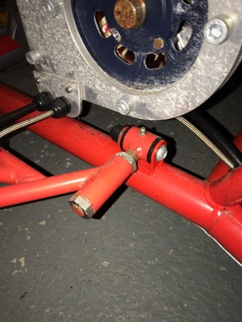 if you have a higher torque power unit than originally designed for which i think was based on the zetec 1.6 engine I was planning to do a structural analysis on the bracket in solidworks to get an idea of the problem - i dont think anyone has had an actual issue with the rear chassis wishbone mount but they deffo have with the old design on the front. |
|
|
|
Post by kiwicanfly on Nov 24, 2018 18:22:50 GMT
I think the chassis i have is ok at the front now because the design has changed and its similar to Kiwi's that survived his incident Mine is no longer standard at all, I modified it. Will pop a link in later, just off to "test" it again. |
|
|
|
Post by jacksdad on Nov 25, 2018 1:18:55 GMT
simulated rear lower wishbone front bracket using a torque of 250 lbft ratio 7:1 and 60 cm wheels assuming forward directed force at the axle and taking moments etc gives a force vector pushing forward and into the chassis at the bracket. The stress even at this torque is 2 ish times less than yield stress so looks ok 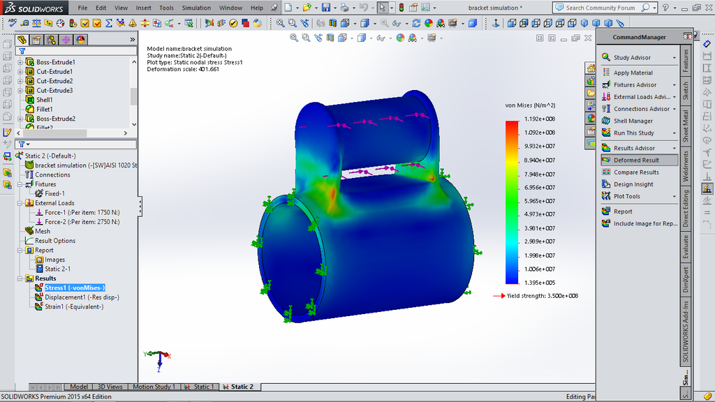 |
|
|
|
Post by kiwicanfly on Nov 25, 2018 8:10:25 GMT
These are the changes I made to my front suspension mounts mevowners.proboards.com/post/101659/threadYou will see that the front of the tabs on the front mounts have been extended and a support plate put under each of the four mounts. Not tricky to do but it does involve welding. Certainly did the trick for me though however an alternative solution would have been to drive a little more conservatively  |
|
|
|
Post by OnrampApex on Nov 26, 2018 1:30:36 GMT
Thanks guys. I'm not sure what I'm going to do about that issue, but I really don't want to cut into my powder coating if I can help it. I'm also having trouble understanding how a bar from side to side is helpful (if the cracking starts from braking torque, a transverse tube is in the wrong direction; if it's from cornering loads, both sides are getting pulled the same direction, albeit in different amounts.) I'm thinking about milling something that connects the pivot bolt to the nearby steering rack mounts, to spread the load out and stiffen up the two thin tabs. Either way, I'm going to put that issue on the back burner for now - as an engineer I could spend all year designing stuff but I need to keep moving forward. I appreciate the heads-up; I'll make sure to revisit this before I do any spirited driving  |
|
|
|
Post by jacksdad on Nov 26, 2018 7:30:24 GMT
I think thats sound and I agree a local bracing to support the bracket is a reasonable solution - I think a cross member will stiffen both brackets if they are being stressed inboard during acceleration or outboard during deceleration and transfers some of the lateral force on the bracket weld to tension or compression in the cross member
|
|
|
|
Post by OnrampApex on Nov 26, 2018 12:17:01 GMT
Of course the load on those is inward during braking - I should know better than to try to do tech late at night! And since there is no acceleration-based loading at the front, I'm sure braking is the key contributor to the problem at that end. Thanks for making me think about it during the daytime! I may do a cross member at some point after all...
|
|
|
|
Post by OnrampApex on Jan 25, 2020 19:36:45 GMT
|
|
|
|
Post by OnrampApex on Jan 25, 2020 19:39:26 GMT
But of course there seems to be some sort of misalignment problem - the right side mount has no play, but the left side bracket appears to be maybe .75 inches / 19mm too close to the center. Has anyone else seen this issue? I'm not entirely sure what to do about it at this point, except maybe make some vertical spacers that allow this horizontal offset.  |
|
|
|
Post by kiwicanfly on Jan 25, 2020 21:04:51 GMT
Mine was pretty much the same, I have a Vibratechnics mount but the positioning is pretty much identical.
Can you spin the top plate 180 degrees? If so that looks like it would put three holes in useful positions.
I actually didn't use any of the provided holes, I drilled new ones, I wanted a round bolt in a round hole!
|
|
|
|
Post by OnrampApex on Jan 25, 2020 23:21:17 GMT
Thanks for the confirmation that I'm not crazy... I took it apart and tried to turn it around today; it's definitely asymmetric (there is a pin in rubber half that engages a slot in the engine mounted bracket) and the torque snubber wouldn't work in the opposite direction.
After a bunch more digging here I've decided that this is common, and everyone just drills new holes and avoids looking at the offset. I was drawing a blank on how to use those square holes anyway... new holes it is!
|
|


