|
|
Post by pocketrocket on Oct 28, 2015 8:55:02 GMT
its ok mate, the only aussies that watch it are on the east coast anyway. Much like Mexicans really. Real Aussies watch AFL  |
|
|
|
Post by pocketrocket on Nov 2, 2015 1:03:15 GMT
I had the engine/transmission back out, while I welded out the new mounts. Figured it was as good a time as any to fit the aluminium flywheel & heavy duty clutch 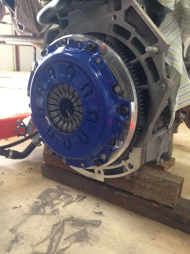 |
|
|
|
Post by pocketrocket on Nov 2, 2015 1:04:14 GMT
Front engine mount 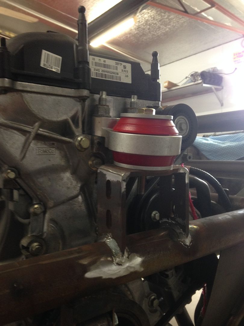 Transmission mount 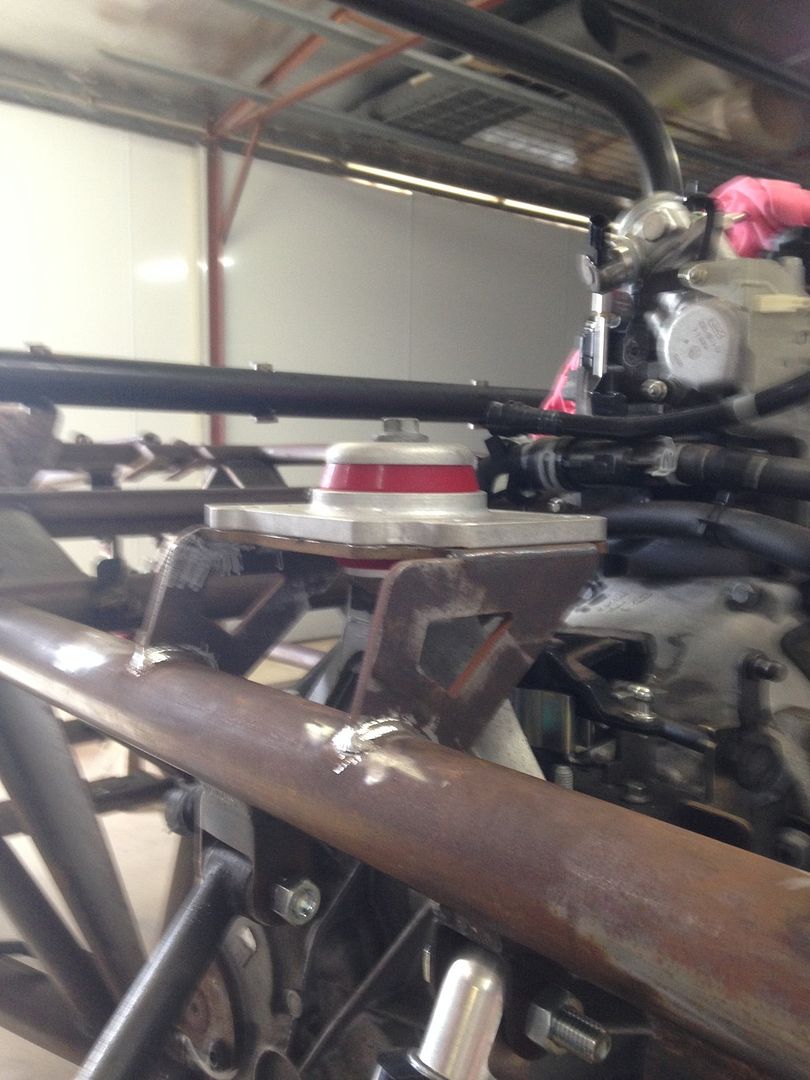 |
|
|
|
Post by pocketrocket on Nov 2, 2015 1:09:53 GMT
Used my waterjet to make a bit of a template layout, for a jig to fabricate the new front lower control arms 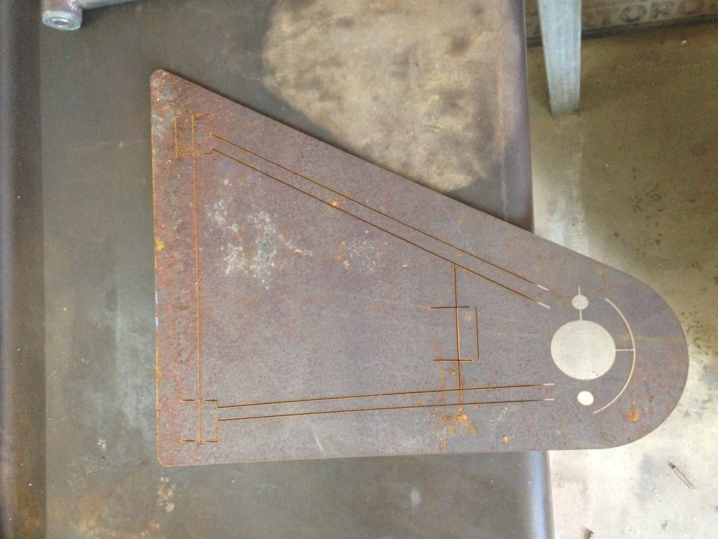 Used the existing arm to ensure correct spacing & alignment of the inner pivot bush tubes, to make sure that they'll fit the mounts that are on the car. You can see the change in offset to correct the geometry. 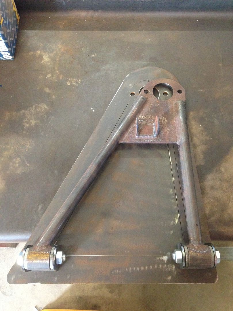 Fitted the new ball joint mounting plates, that I water jetted from 5mm mild steel 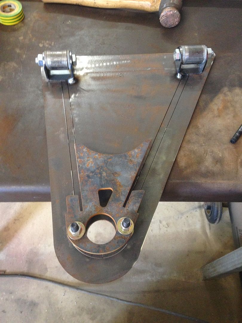 Spent a bit of time ensuring the ball joint plate was correctly spaced to be at the tube centreline height 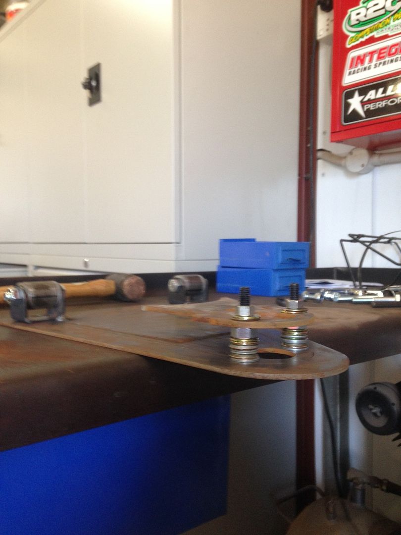 |
|
|
|
Post by pocketrocket on Nov 2, 2015 1:14:38 GMT
Had previously measured the angle of the tubes, then used my tube notcher to scallop the tubes at the correct angle to fit the inner bush tubes, & cut to leave a bit of "green", so that I could later mark & cut to the correct length. When marking round tube, I like to use tape as the marking edge, so you have a guide mark a full 360deg around the tube to be cut. 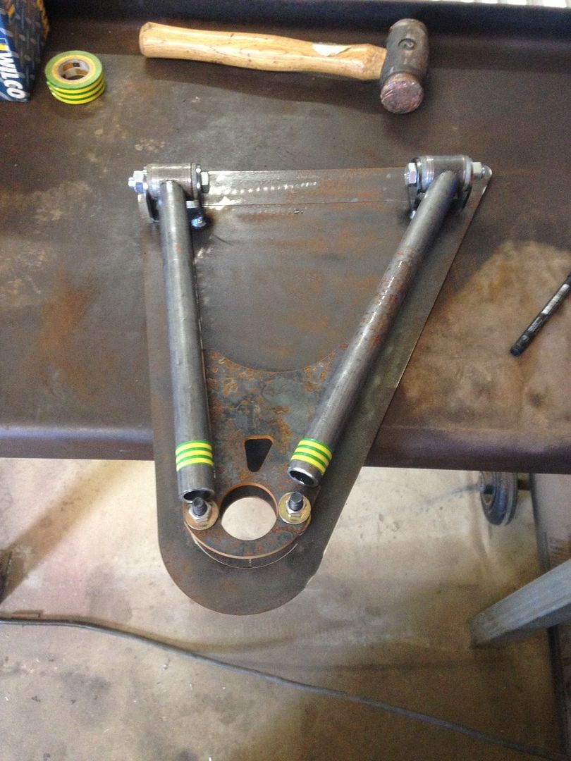 Put all the bits into position & we're ready to tack & then weld 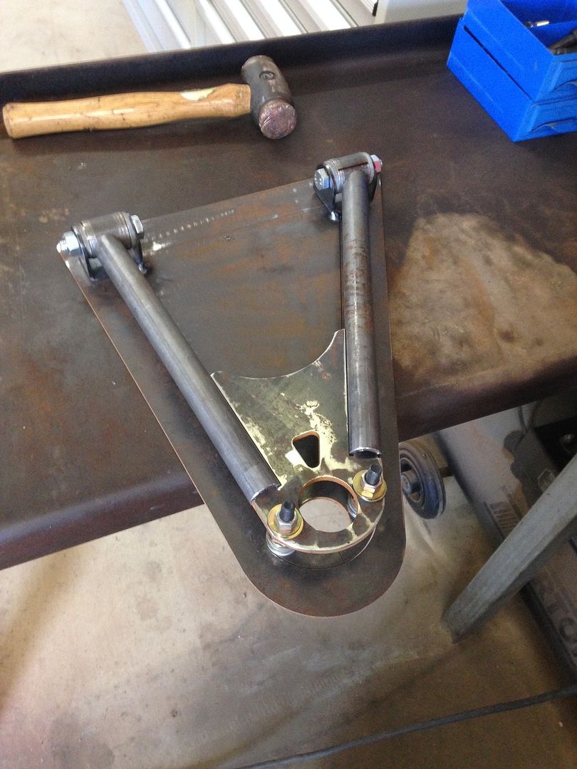 |
|
|
|
Post by jacksdad on Nov 3, 2015 18:05:59 GMT
V nice work looks good so will it be around 9 degrees castor at mid setting ??
|
|
|
|
Post by pocketrocket on Nov 4, 2015 0:30:48 GMT
V nice work looks good so will it be around 9 degrees castor at mid setting ?? hopefully that will be around maximum (or there abouts) to be honest, any reduction to what it had would be an improvement |
|
|
|
Post by pocketrocket on Nov 16, 2015 1:42:05 GMT
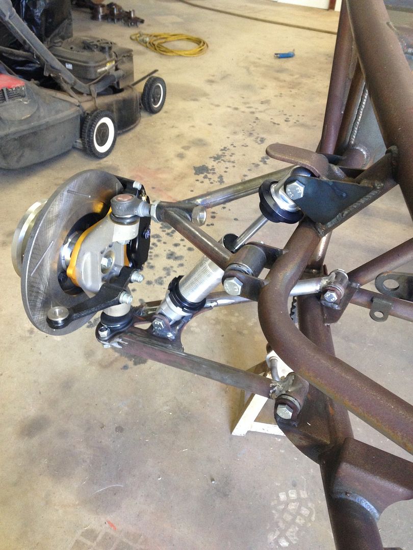  new lower control arms, with rectified geometry trial fitted. Much more at ease with the alignment/geometry now. With the uppers spaced evenly, we've got 5deg +be caster & it appears (by chance rather than any kind of design expertise) that each shim washer movement fore/aft on the upper is about 1deg in caster change. That all said, this is just with the chassis rails level & the bolts all just hand tight, but I'm confident it'll be in the ball park. Let's face it, it couldn't have really been any worse than where it was |
|
|
|
Post by pocketrocket on Dec 23, 2015 5:35:13 GMT
There was a little issue with the Cosworth intake manifold I'd purchased. Its for a Duratec, but clearly not for a Duratec like I have (I think mine is just a much later model than what the Cosworth intake is designed for). So, this is what I started with 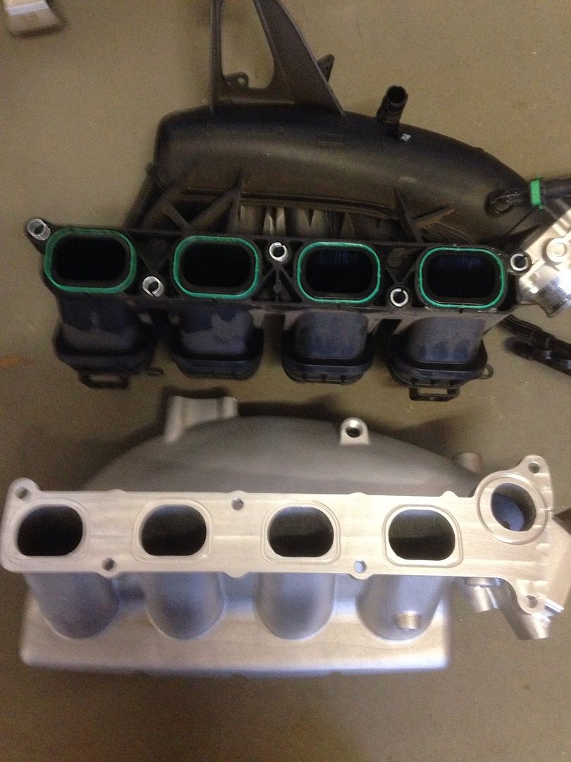 I wasn't sure how close the 2 actually were, but a few measurements indicated the flange pattern might be close. Question was, would it be close enough to alter? Would there be any unforseen hurdles to jump, if the flange was modified? So I started out by using my waterjet to make a template of the original intake's flange. Then laid that pattern onto the Cosworth intake flange, to see where everything lined up. Turned out the actual runners (port spacing) was very close. Not 100%, but close. The EGR port was clearly going to be the biggest issue. The bolt spacing was close, but wasn't ever going to work & there would be a bit of aluminium on the Cosworth flange that would need to be removed. My thinking was that I'd be able to waterjet a flange from 10mm aluminium, mill the existing flange off the Cosworth intake, then weld my new flange, onto the Cosworth intake, & basically fill the gaps. Sounded easy.... As I'd need to outsource the TIG work, I wasn't sure if it were going to be possible/practical to be able to weld around the runners & a few other places. Figured it might be a bit tight, for the hand piece & still be able to see the weld pool. So, before I went any further, I took the template & the intake around to a mate of mine, that runs an engineering/machine shop. He's ever so good at what he does (he's actually build 2 street rods at the moment for himself). I ran my idea past him, as he'd be the one having to weld it up. He confirmed my concerns, with welding access. We spent quite some time discussing alternatives & in the end, he suggested we leave the existing flange in place. He'd have me back prep ("V" out) around the inside of each port, so that he could weld around the inside of each port, without encroaching to much on the port itself - this would seal it up. He'd then weld around the entire outside of the 2 flanges & mill the weld back, to dress it up so it wasn't noticable. I'd then have the thickness of my new flange plate & the existing flange, to be able to blend the ports out. Amongst all this, he'd mill the EGR section off & weld in a blank, where that accessed the main air entry tract. So, the other day I picked it up. He'd done a fine job, & unless you were actually looking for a modification, you'd probably be hard pressed to notice it. Being xmas and all, I spent this morning bending out the ports, using the template as a guide to grind to. There are a couple of small blemishes around the port edges, where the TIG melts it away, but they're not worth worrying about. Considering what we've done, I'm pretty happy with the way its turned out. Happy days 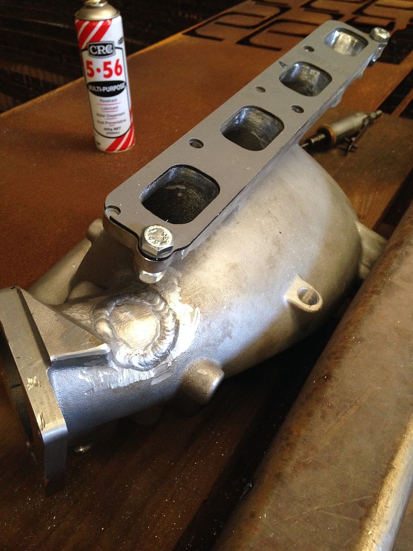 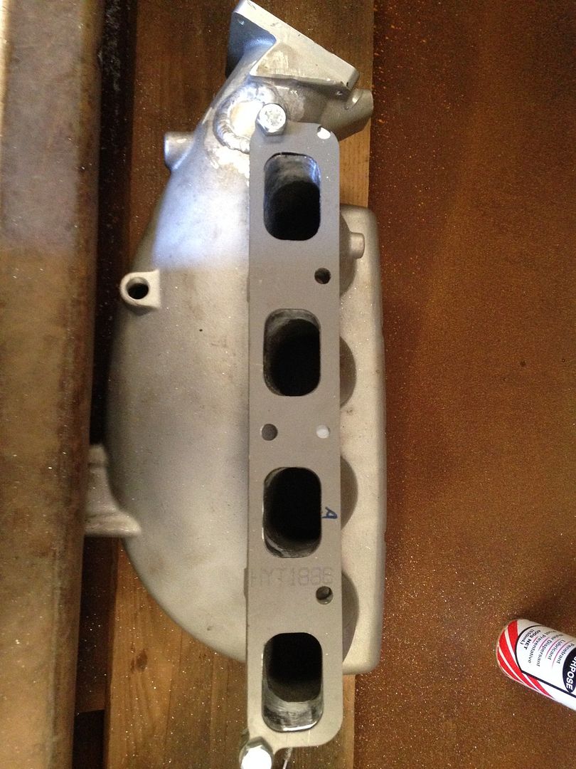 |
|
|
|
Post by dgibson on Dec 26, 2015 23:15:33 GMT
Very impressive work. Keep it up!
|
|
|
|
Post by pocketrocket on Jan 7, 2016 0:57:33 GMT
With not a whole lot of room to play with & angled tube in every direction, it took 3 goes to come up with a bracket that located the fuel tank in the correct place, with clearance on all sides, held the tank high enough so the sump didn't hang out the bottom & to get the scallops for the tube the correct elipse shape to get a nice weld. Having had to concede defeat with my idea of 2 tanks, gavity feeding to a surge tank, with no lift pump, & not really liking the tank that is offered by the kit manufacturers, I settled on a standard aftermarket tank by Aeroflow. With a capacity of just under 20lt, I'll combine this with a 2.5lt surge tank. I figure a car like this, I'm unlikely to be travelling more than 100 odd kms at a time so the range isn't of great importance. For what its worth, the capacity I have will be 2.5lt more than the manufacturer's offering (due to the surge tank). The kit manufacturer also calls to mount the tank directly to the aluminium floor. Most of the builders in the UK seem to do this, and its fine, but I didn't like the idea. I could forsee the floor cracking around the mountings. Hence why I dicked around to come up with something to mount to the chassis tube. The UK cars also don't have any of the angled tubes (the ones on the floor, the ones behind the seats or the ones in the rear bulkhead) so there's would be a whole lot easier to work with. 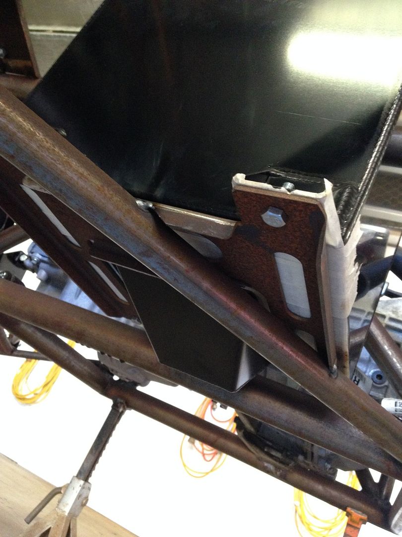 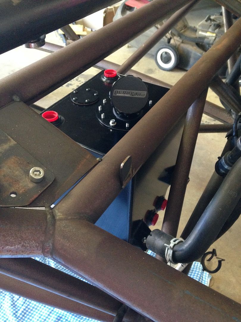 This shot makes it look like there is heaps of room. Actually, this photo was taken after attempt #2. I cut it back off & made another complete mount. This attempt wasn't high enough (to keep the sump from protruding below the lower rails) and I also wound that I would be able to alter the scallops, which would allow the tank to move away from the chassis centreline by another 10mm. I needed to give myself enough room as possible there, now, because there is still a whole lot of nuts that needs to run down the centre of the car. 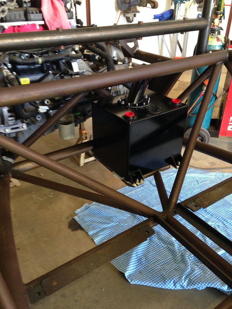 As always, the last bracket turned out the nicest. Doesn't look much, but fk me there is some hours & serious hair loss in it. The first attempt was one piece, but found it a right prick to bend the strengthening/mounting flanges. The 2nd attempt was simply a modification to the first. But by then it looked butchered & still wasn't right. So I just made another one. This time made it in 3 pieces so I could just bend the flanges in my brake. Then tacked together, then clamped to the bench to weld (couldn't afford any distortion or it would stress the tank when its bolted in which would likely lead to cracking). 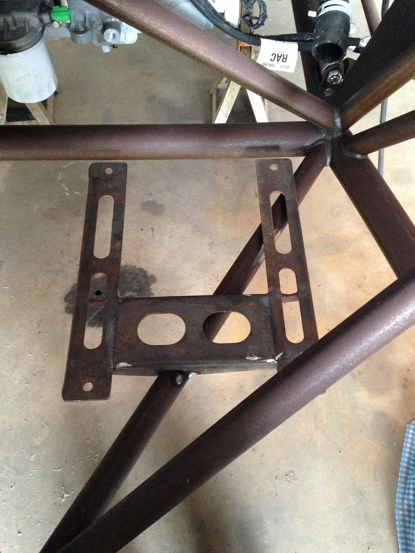 I guess I could have just welded something flat to the tube & then simply spaced the mounts up, but I didn't, for 2 reasons. I wanted to support the majority of the floor of the tank, &, when the chassis is painted/powdercoated, the preperation & coating wouldn't be able to get right into the underside corners & would be prone to corrosion. Now to replicate something similar for the other side, behind the driver, to mount the surge tank/high & low pressure pumps, filter & non-return valve. |
|
|
|
Post by kiwicanfly on Jan 7, 2016 1:56:06 GMT
The kit manufacturer also calls to mount the tank directly to the aluminium floor. Most of the builders in the UK seem to do this, and its fine, but I didn't like the idea. I could forsee the floor cracking around the mountings. Hence why I dicked around to come up with something to mount to the chassis tube. The UK cars also don't have any of the angled tubes (the ones on the floor, the ones behind the seats or the ones in the rear bulkhead) so there's would be a whole lot easier to work with. My certifier demanded better tank support for the same reason - floor mounting cracking. Fortunately I will not be carrying around all those extra bracing tubes so a couple of 16mm RHS welded between the rear chassis tube and seat mount tube solved it. |
|
|
|
Post by casesensitive on Jan 7, 2016 9:40:10 GMT
Really liking that extra support. The tank sitting on the floor has never sat easy with me, but I'm taking the same easy route UK builders tend to take, mostly due to lack of skill! My next kit car, if I ever finish this one, will be much better :-)
|
|
|
|
Post by pocketrocket on May 16, 2016 0:24:57 GMT
Getting 2 car building shed time weekends in a row, I'm just about doing backflips with excitement. After the radiator schamozzle last weekend, decided to move onto the steering rack. I believe the rack to be from a '83 era Ford Sierra. Looking through all the stuff I picked up with the car, seem to be missing tie rod ends. I'll deal with that during the week. Following Kiwi's build in NZ, where bump steer is taken a bit more seriously, Kiwi appeared to find the best solution was to space the rack up 12mm & then extend the rack length. So, rather than me reinventing anything, I figured I'd take advantage of his time, learn from his mistakes & save myself a bundle of heart ache, by just starting by spacing the rack up 12mm. I'll use that as my starting point then work from there. So started out by centering the rack within the chassis (lower control arm mounting points). I dabbled with rack location fore & aft for Ackerman, but, with my crude string lines & chalk, I couldn't really see much variation, by moving the rack within reasonable allowances on the existing chassis brackets, so pretty much just went with centralizing everything. Then measured up for a spacer. I wanted to make it one piece, bridged between the 2 mounts because it appears more substantial. Whether it actually would be or not, buggered if I know. So, came up with a shape & some relieving that I thought looked like it would appear to be a professional product (looked cool). Waterjetted it out. Had my first go at routering the edges (need a bit of practice to just smooth it out a bit). Found the passengers side crush tube on the rack mounting sat a bit proud of the bottom bracket. I contemplated just cutting it off, then thought it might make life easier in the future (if ever the rack needs replacing), if I counter bore a relief on the spacer to accept it. I don't have a mill or any mill tooling (of the correct size) to do this. So set him up in the drill press with a sheet metal rotor bore bit. Drilled to the required depth with that, then chamfered the inside of the hole which removed the taper left by the rotor bore. Deburred all the edges & bugger me if it doesn't all fit the way I'd hoped. 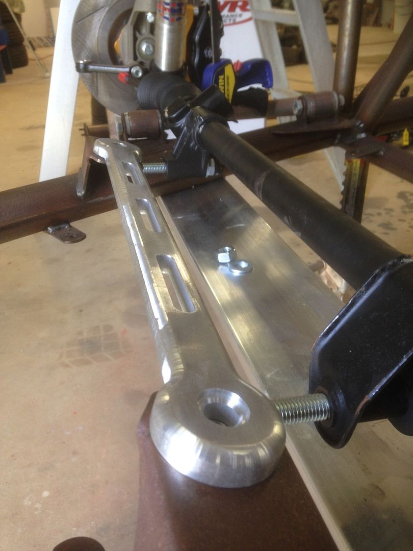 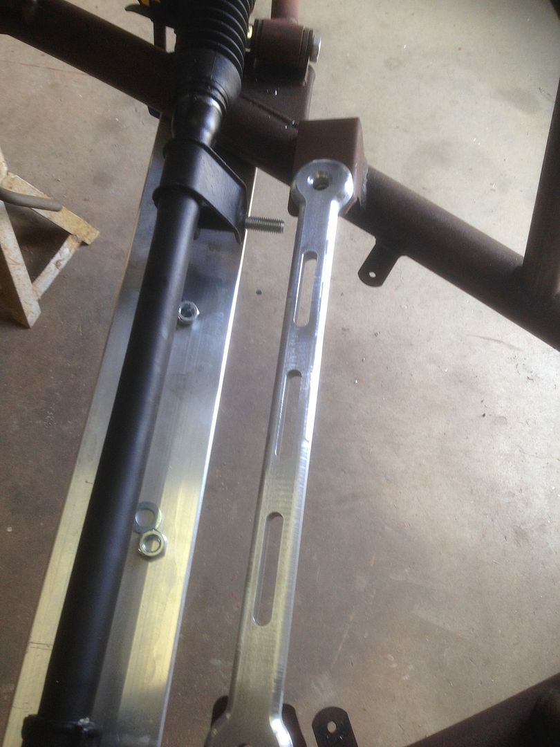 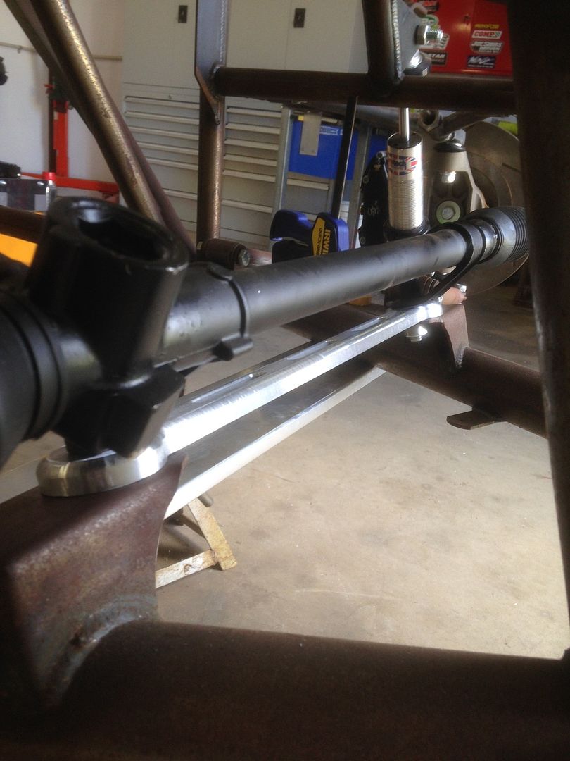 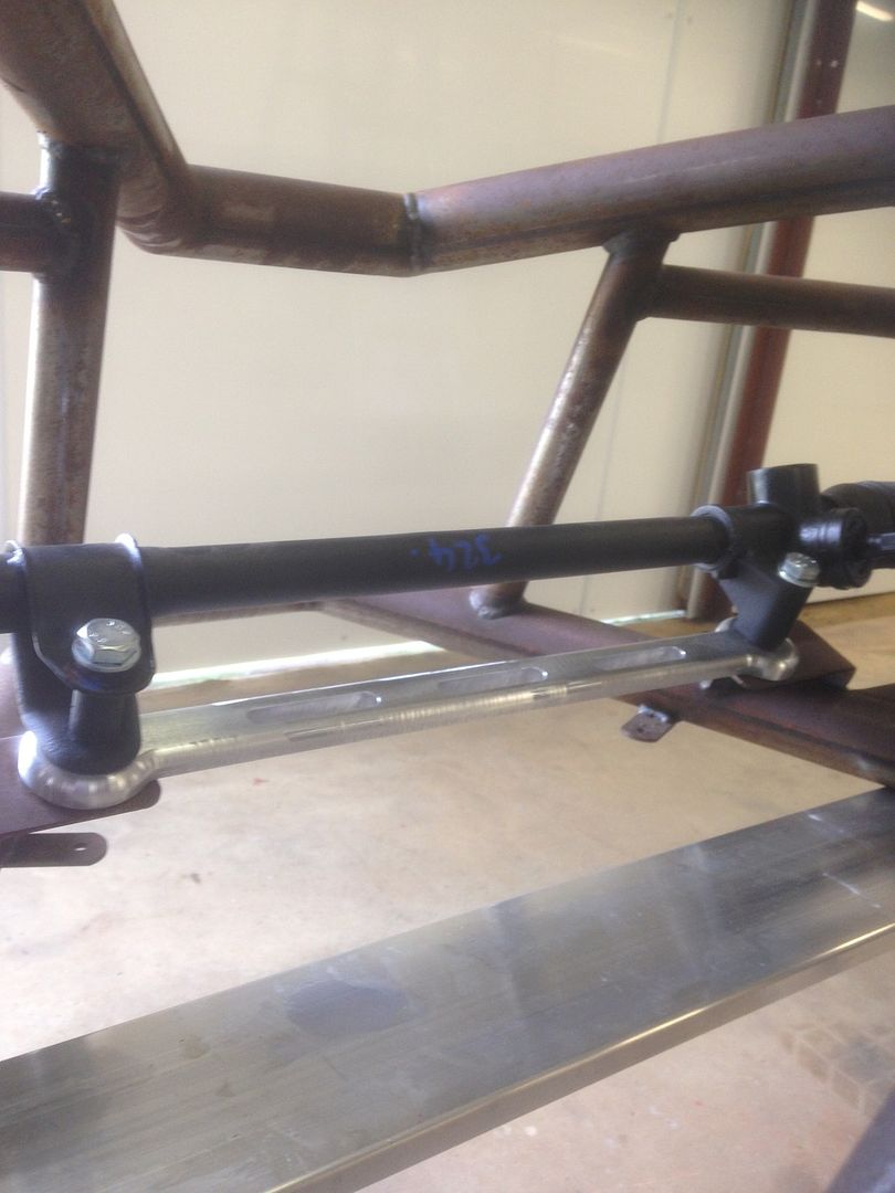 |
|
|
|
Post by pocketrocket on May 16, 2016 1:05:41 GMT
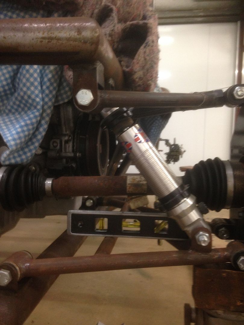 This is concerning me. I would expect ride height would be where the lower control arm is level (under acceleration). Notice how much compression is remaining available on the shock absorber (not very much). Is everyone elses like this? I'm actually thinking that my lower control arms are slightly too short. The reason I think this, is that: * Along with the shock absorber bump travel * The camber adjuster is also out of adjustment (bottomed out) with the rear upright set for zero camber, so there is no available adjustment for negative camber * The rear track width is 50mm narrower than the front (I would expect it to be maybe 25mm or 30mm at the most) So, as per the thread I started in the suspension section, I'm curious as to whether the Sonic might use shorter lower control arms on the rear & I might simply have a set of those by mistake |
|


