|
|
Post by kiwicanfly on Jan 11, 2015 5:50:17 GMT
I cant understand why some builders struggle to fit standard designed for components. I think the answer is quite simply here Nigel, we struggle to fit because the damm things wont fit. For example on the brake situation. I have a set of RD uprights and hubs , 280mm disks and Hi-Spec calipers. When the disks were fitted to the hubs and the calipers fitted to the RD caliper brackets and tightened up with standard M12 cap heads the disks would not turn. I then skimmed a little off the disks and found out in normal road use the disks expanded enough to rub slightly but on street sprint boy did they rub badly so had to be skimmed some more, I could have eased the inner face of the caliper but choose to do the disks instead. I could have packed the calipers with a spacer between the caliper and carrier but I am not comfortable with that as I believe it is wrong. I did do it as a temporary measure on the sprint though. Should I have had to do any of this? Of course not and for once this is nothing to do with RTR. Your tone implies that we are doing something wrong (although that may not be the case) but until someone shows me what the correct solution is I can see no other solution. Just happy to have easy access to a lathe. Although I'm no racer and have never managed to get my discs to glow, I've done a number of track days, continuous hot laps and never experienced binding brake discs, thus needing to start machining or shimming the discs for clearance. To repeat mine rubbed whilst still in the garage, there was no way they would turn even when cold. |
|
|
|
Post by nigel on Jan 11, 2015 8:22:58 GMT
I cant understand why some builders struggle to fit standard designed for components. I think the answer is quite simply here Nigel, we struggle to fit because the damm things wont fit. ....... Point taken Kiwi, but WHY won't they fit? Looking in from the outside so to speak and reading through duratec1999cc build thread once again I suspect that either the Febi Bilstein Hubs are different in some way or the calapier carrier bracket mounting holes are not in the correct position. (Distance from the Hub Centre) I have re checked mine and the calapier carrier bracket mounting hole centres are as near as damm it 105mm away from the Hub Centre, are yours the same Kiwi? As far as I'm aware the Rocket and Sonic rear uprights are the same and should allow the Builder to fit either the standard 1.8 focus calapiers and discs or the larger ST ones. Now if for some reason or another rear uprights are being manufactured and supplied that will not allow the builder to simply bolt the standard together then RTR should be made aware and address accordingly. I have always advocated that 'it should be up to the manufactures to ensure that the products are well made and fit for purpose before they are handed over to the customer (builder) for assembly' nigel |
|
|
|
Post by duratec1999cc on Jan 12, 2015 23:42:41 GMT
I'll measure from hub centre to mounting holes later in the week. Once i have the shims from RTR that fit onto the hub behind the disc, ill see how much the mounting holes need to be elongated out by to create enough disc outer edge clearance.
Been very busy with work, but made some progress at the weekend, on saturday made more bump steer measurements then fitted the rack in the correct position, needed 21mm spacing under the rack.
My chassis is now a roller, I wanted to fit the engine, so on Sunday I started by fitting the front stub axles and hubs, put wheels on, rolled it outside and fitted the engine.
I'll post details and photos tommorow eve.
|
|
|
|
Post by duratec1999cc on Jan 14, 2015 0:58:42 GMT
Just posted my bump steer measurements here: mevowners.proboards.com/thread/6140/bump-steer?page=4I decided upon 21mm of spacing to go under the rack and aligned the rack so that the track rod end ball joint centres formed a straight line from end to end and through the centre of the rack bar. It might not look straight here, but the track rod end is angled, so the line from the centre of its ball joint to the centre of the rack bar is straight. I could have fitted the track rod ends opposite handed so the arm is angled the other way but the end result would still be the same. 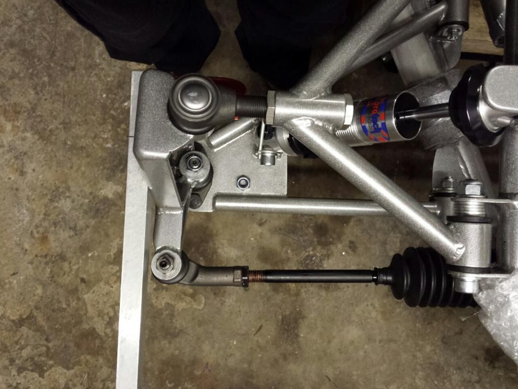 I had previously centred the rack, so once i had aligned it in relation to the track rod ends and with the 21mm of washers clamped under it i marked it and drilled it. I wasn't aiming for it but it did turn out that the holes ended up symmetrical in their mounting brackets, with a slight bias towards the rear: 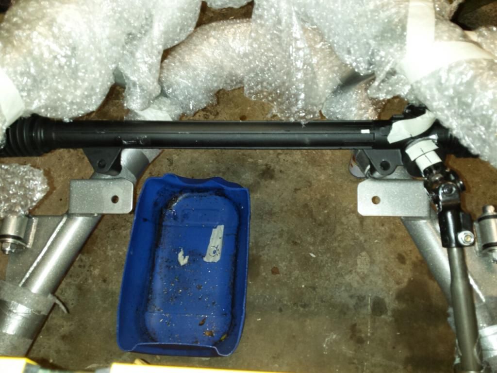 The rack and mounting brackets holes lined up perfectly, i used M12 grade 12.9 110mm bolts and M12 DIN9021 washers which are a larger diameter than standard From A washers and are 3mm thick: 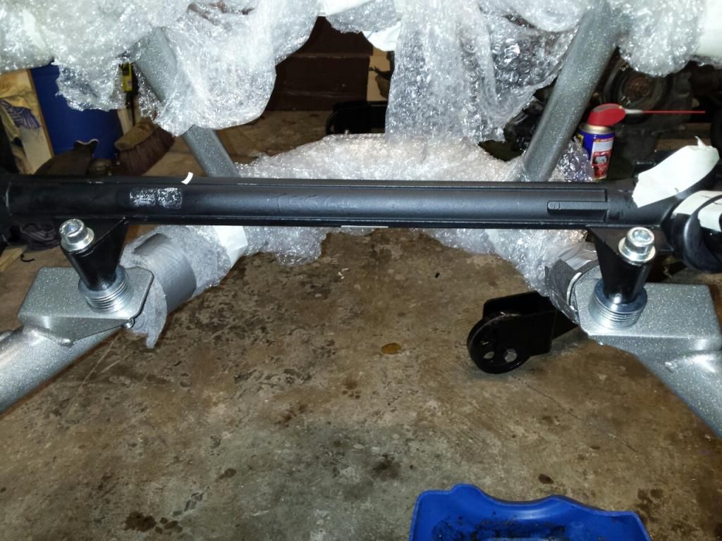 Next post will be about fitting the engine... |
|
|
|
Post by duratec1999cc on Jan 15, 2015 0:38:20 GMT
Decided to fit the engine on sunday, i wanted to fit it before fitting any engine cover hinges or brackets so i know whats required, its a bespoke engine fit and i didn't know how close it was going to be etc. I realised i hadn't degreased the engine yet, it took most of the day to do that so it was dark before i started to get the chassis on the ground. First job was to fit the springs, wouldn't want to forget that! I greased the mating surface between the shock and the spring cup to make it easy to wind the adjuster, i was then able to wind it up by turning the spring and everything moved nicely together because the cup was able to rotate against the shocker: 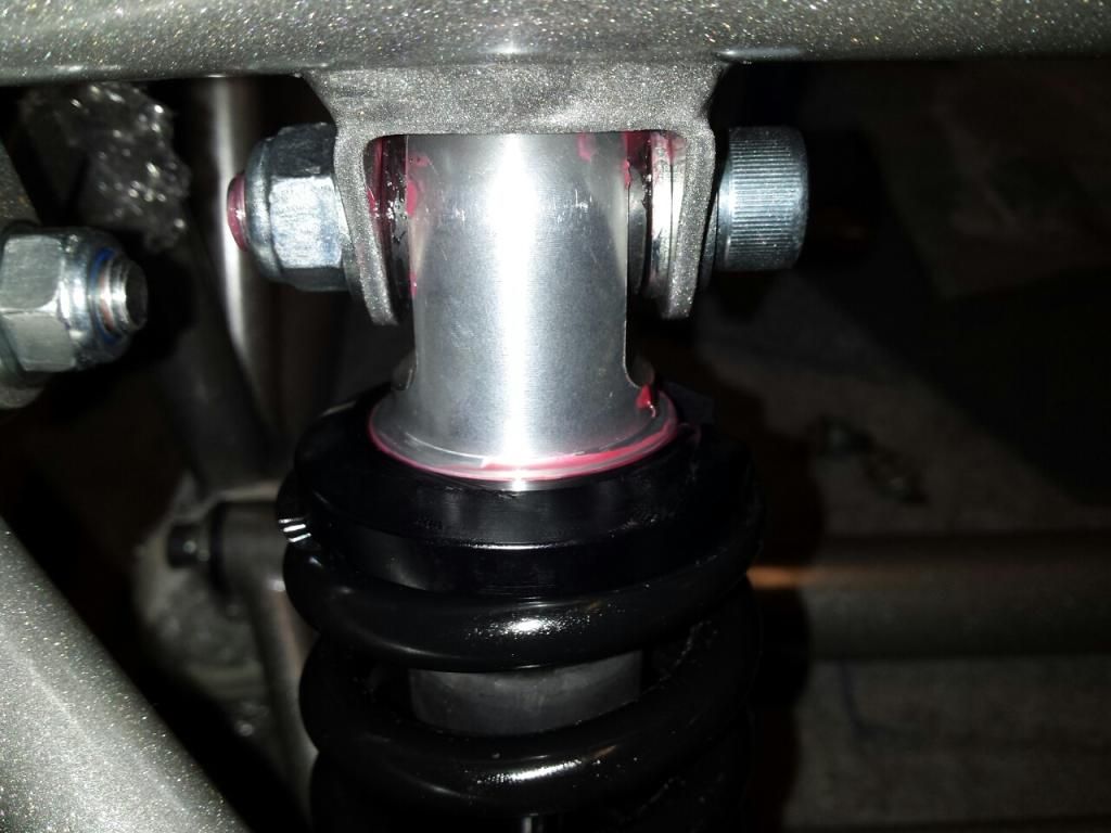 Wheels on and out of the garage: 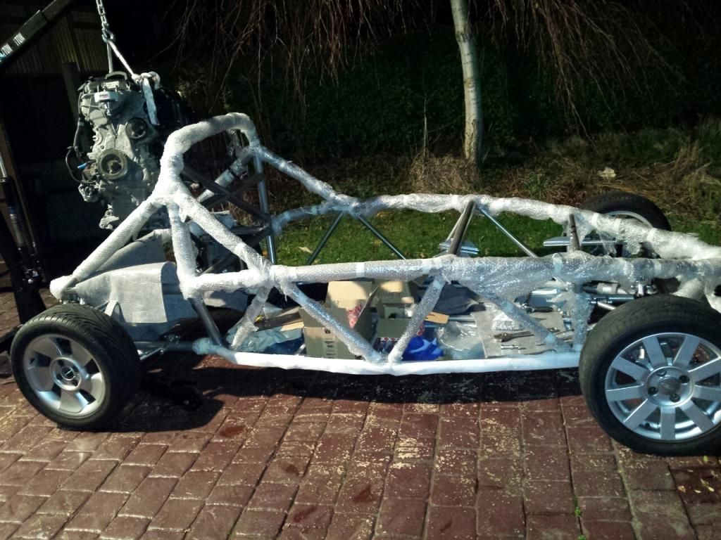 I had a slight issue with one of my sets of 15 inch puma alloys, the only ones that would fit on the back were the propellor style ones, the 9 spoke alloys caught on the top rear edge of the upright as they are thicker on the inside, hence the odd set in the photo. Engine ready to be lowered in: 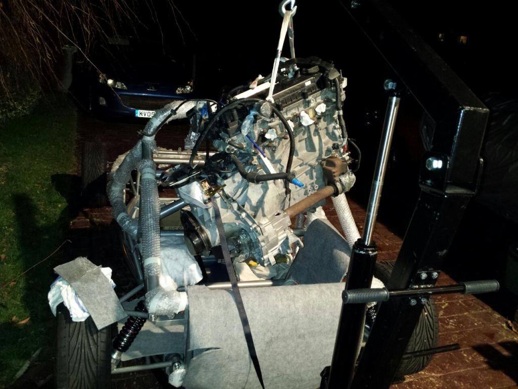 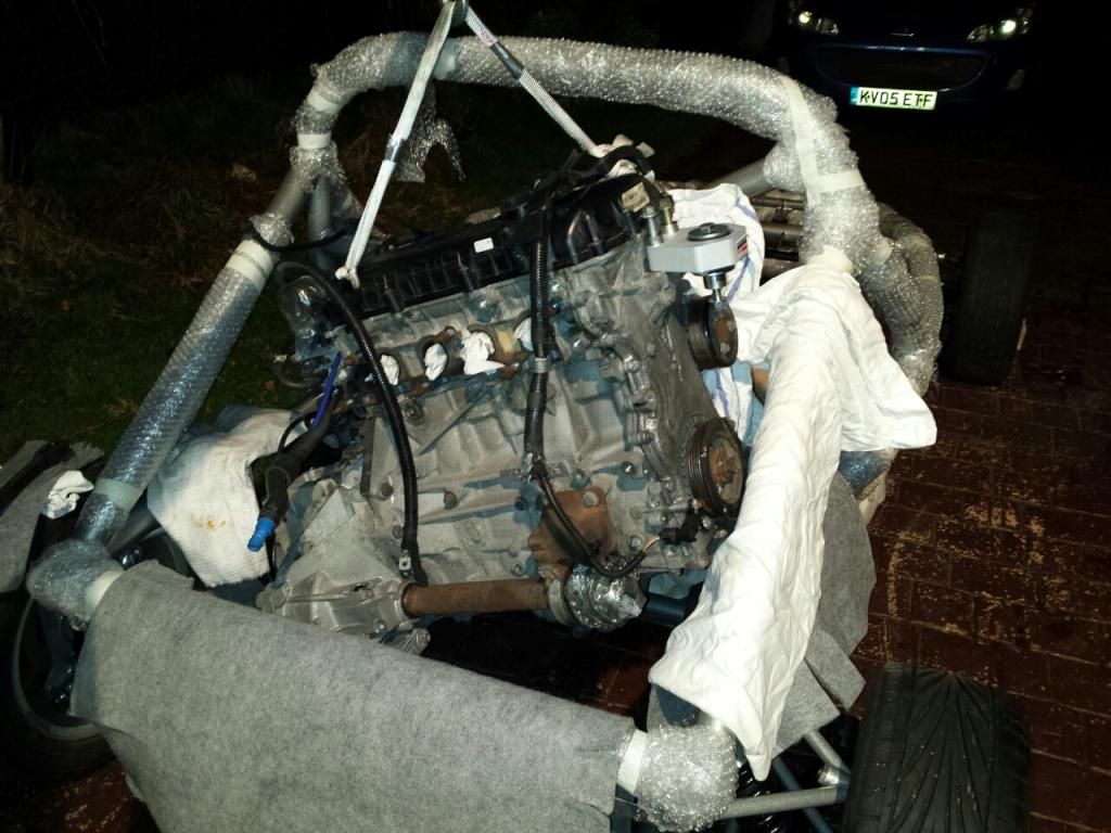 I needed to open up the rear torque link mounting bracket by a few mm to get the standard torque link in, was probably designed for a vibra technics item. 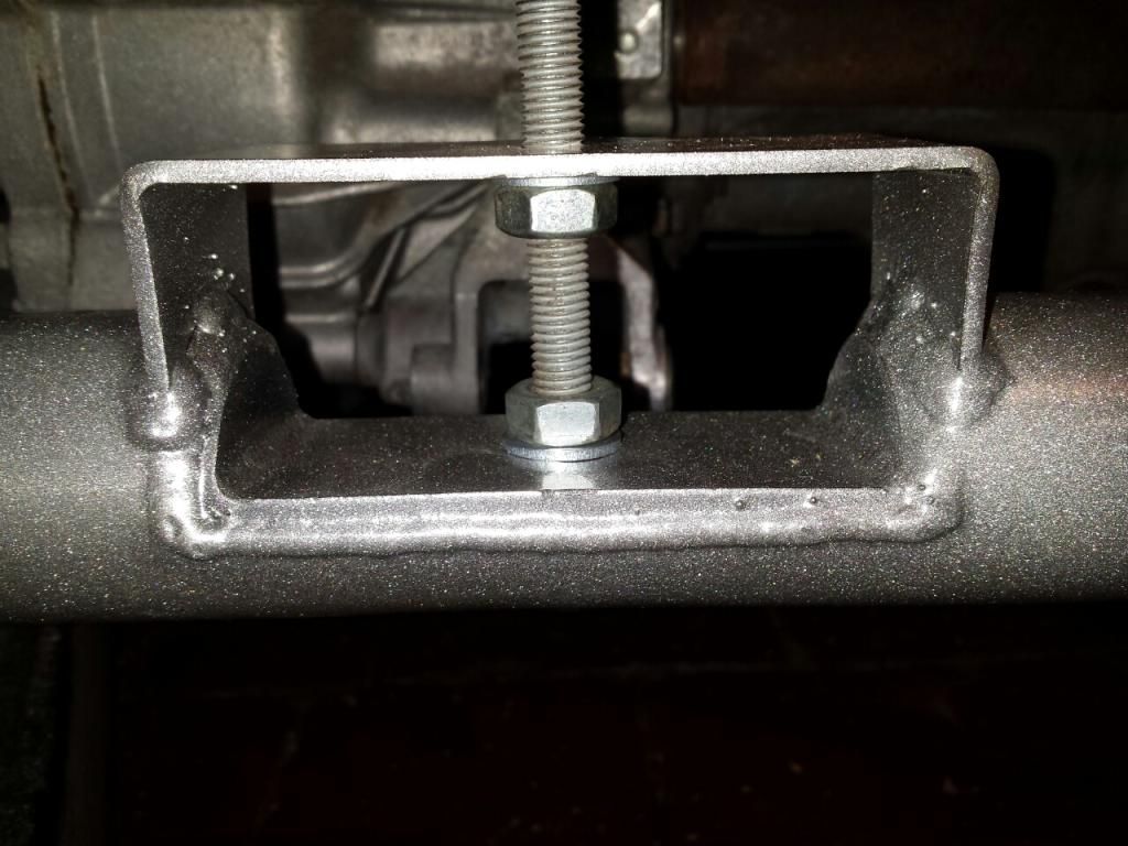 Torque link installed, the non-locking nut is just temporary: 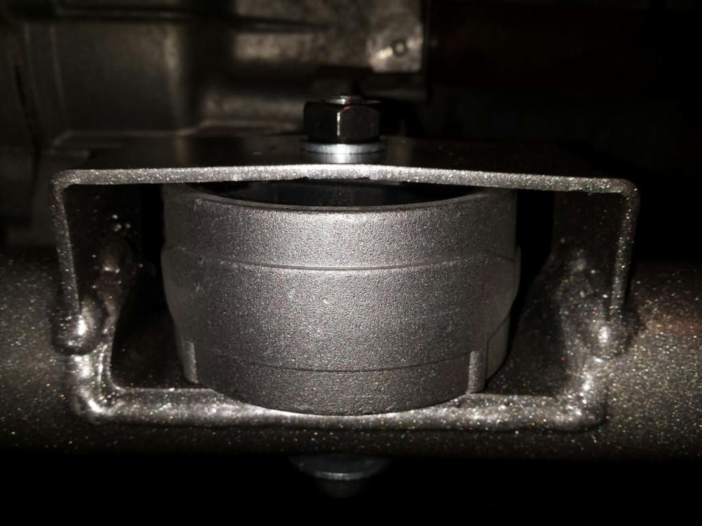 I was then able to fit the Vibra technics mount on the timing chain side of the engine, and bingo, engine fitted: 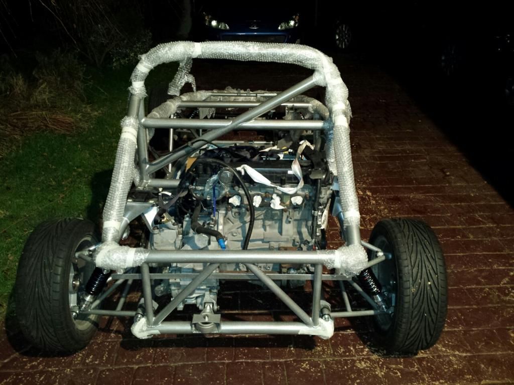 Fits well, nice and level and driveshaft cups line up with the hubs. My only concern is the very little clearance there is between the inlet manifold and the lower rollbar tube, there is only 6mm clearance so its going to hit it under load, even if i am using a vibra technics torque link. 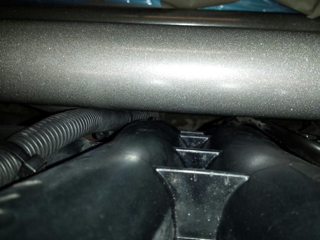 I can move the cable, but the plastic inlet manifold is there to stay for now. Apparently Vibra Technics can make custom mounts, so ill ask how much it would cost to make a torque link thats 10mm sorter, that should give enough extra clearance. I have a set of Suzuki GSXR-750 Throttle bodies for a future mod once its IVA'd, so an adjustable torque link would be better then i can move the engine back to how it is now once they are fitted. Back in the garage ready to be hoisted back onto its dollies, some spare flat nylon webbing from my climbing equipment came in handy to take the load and be nice to the powder coat: 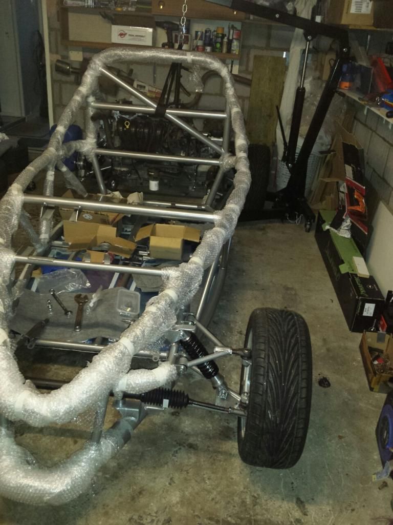 Going to sort out the rust on the front stub axles and fit the front brakes next... |
|
|
|
Post by airforceone on Jan 15, 2015 8:11:50 GMT
The space between the exhaust manifold and the roll bar is about right, sounds about the same
as mine. I have vibra tech mounts all round and have never had the manifold hit the bar, YET...
Are you keeping the engine in place now? Only asking as there is a load of stuff that
needs done around the engine bay that will be far easier with it out. Things like Brake hoses,
rear bulkhead and the engine cover.
|
|
|
|
Post by duratec1999cc on Jan 15, 2015 21:14:10 GMT
Thanks, that good to know, the vibratechnics torque link must be pretty stiff.
I thought it wouldn't be enough because in its previous installation, that same amount of clearance at that spot was not enough even with an uprated torque link.
The main reason for getting the engine in was because it was under the feet in the garage, i needed the space so thought i would put it where it belongs.
It only took less than 30 mins to offer it up and get it in, ill take it out if it causes any difficulties.
While its in I will test fit the exhaust system that RTR made for me, looks the business, i want to see how it looks on the car and how the silencer needs to fit.
|
|
|
|
Post by duratec1999cc on Mar 29, 2015 13:08:43 GMT
I made i bit more progress over the last 2 weeks, i test fitted the new wishbones that RTR sent to me at the beginning of Feb, my castor angle is now adjustable between 5 and 9 degrees, previously the minimum is could achieve was 11.5 degrees. I am happy with this and will run them at 8 degrees initially. They are now off at the powder coaters (same ones RTR use) to be coated in the same silver. The new front wishbones have are 25mm further forward (referring to the position of the adjuster tube) than the other new ones they made when they had my chassis back to sort the alignment issues back in Nov/December. While i was test fitting the wishbones i sorted out the adjuster issue that i encountered last year, the adjusters that were sent with my kit (infinitely adjustable option) would not engage on enough threads with my front camber angle set anywhere from to 0 to 2 degrees. At 0 degrees only half a thread (0.75mm) could be engaged, at 1.5 degrees this was better (4 threads) but still nowhere near enough. I wanted at least 100% of the width, i think the ball joint has a 17mm shank, to that would be 12 turns minimum at 1.5mm thread pitch. RTR had previously sent a pair of full length adjusters (like the ones supplied for the rear wishbones) free of charge when i pointed this out , i just needed to cut them down to length to fit the front wishbones. The adjusters supplied originally where of equal length and the end of the ball-joint shank was only just past the mid point, hence the issue. This photo demonstrates: 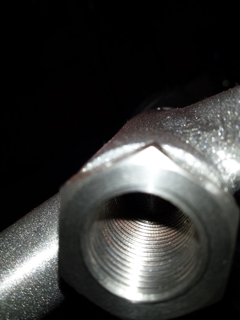 The end of the ball-joint shank is just over half way through the wishbone adjuster tube so only engages on the inner adjuster by less than 1 thread with zero camber setting To solve the problem i cut down the full length adjusters so they are just 1mm shorter then the length of the tube on the wishbone (54mm) and used the nut that came with the ball joint to lock it in position, IMHO there is no need to have 2 equal length adjusters as was supplied. These are the original adjusters shown in the position they would be when installed with zero camber setting (ignore the lock nut on the ball joint shank, that's for use with the full length adjuster later on) 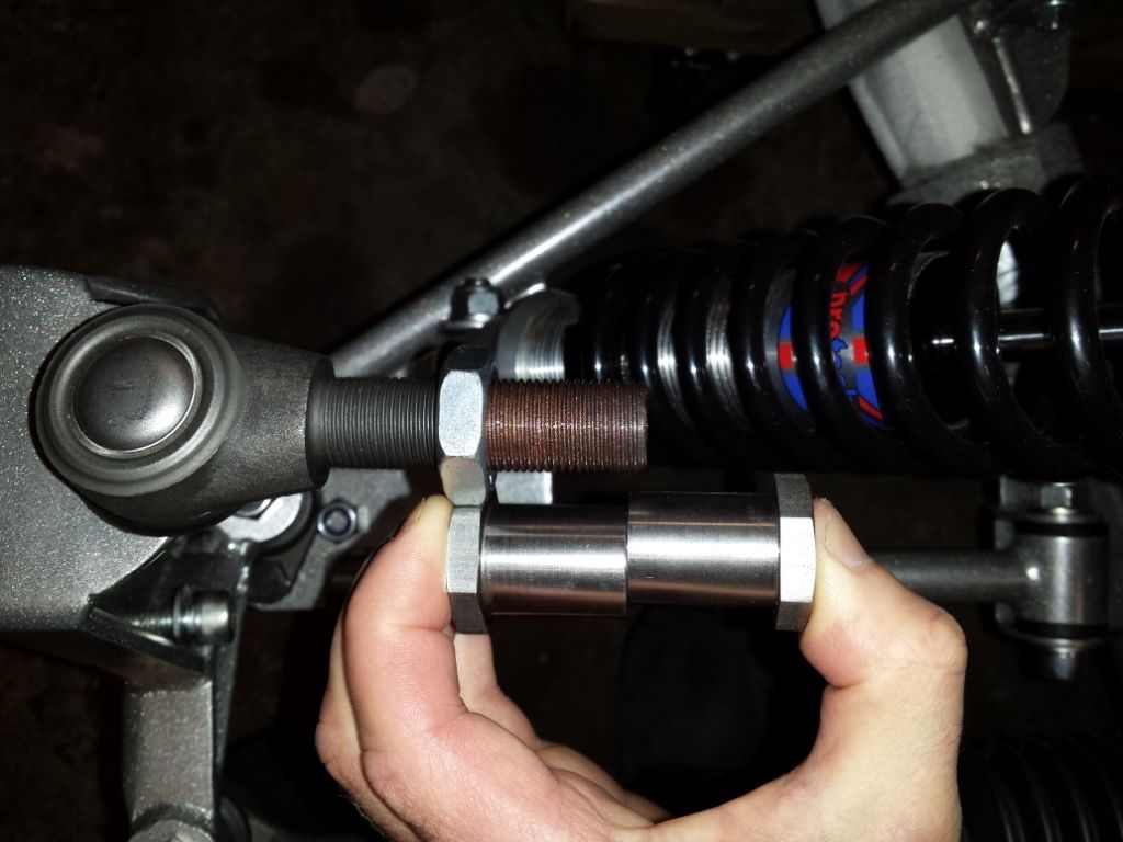 clearly that is not acceptable. Here is how it looks with the full length adjuster: 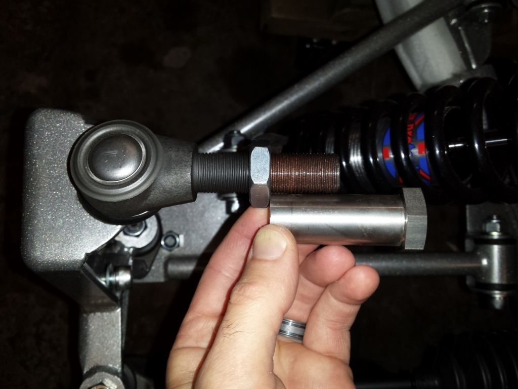 Thats much better, almost twice the width of the shank is engaged. Here it is ready to be screwed in: 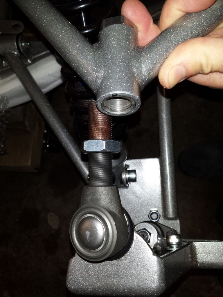 |
|
|
|
Post by duratec1999cc on Mar 29, 2015 13:46:19 GMT
I decided i wanted to improve the steering column extension, i used the original steering column tube and bar from the donor car (Ford Puma) as the steering column extension as this was already made for purpose and fitted on the focus column and the fiesta Mk3 UJ nicely. (see previous posts) Im not happy with using a rose joint on the extension bar as there will always be some play in it, this this setup there is no detectable play between the tube and the bar, especially now i have 3 bearings between the tube and the bar. The original column already had a thrust bearing at the top of the tube, i managed to find a pair of bearings that would fit between the bar and the column tube so i now have 3 bearings, bottom middle and the original top trust bearing. The bearings are for a mountain bike bottom bracket and fully sealed. 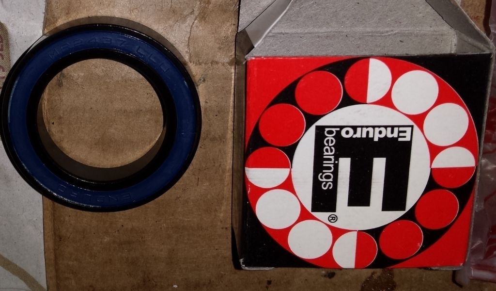 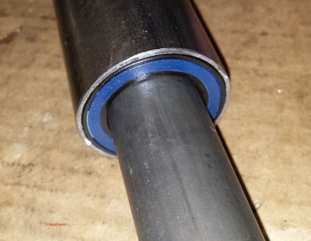 Brackets made up from 2mm stainless and 5mm angle alloy, the Joker pedal assembly which i have received will fit onto the stainless steel plate, measured up and holes drilled ready to be bolted on. The plate will bolt to the chassis and to the pedal box mounting brackets and provides a secure mounting for the column support bracket and the pedal assembly. 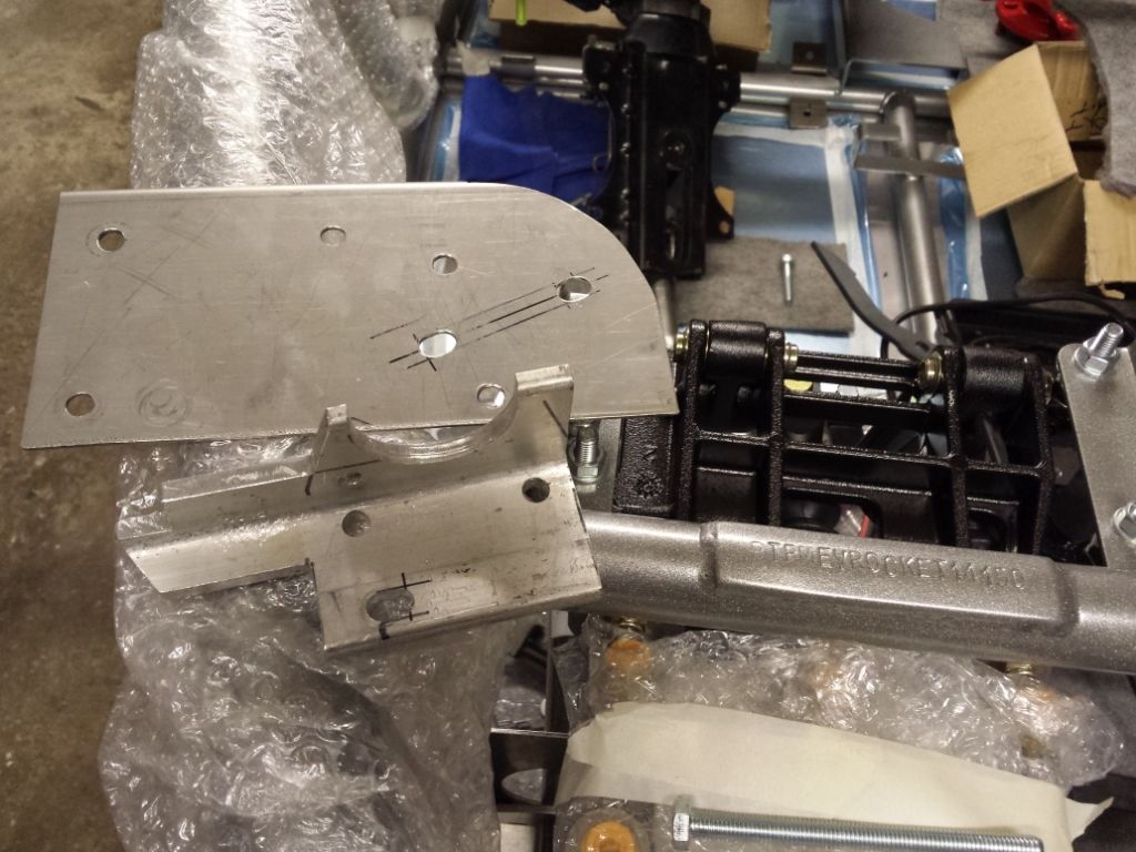 I have designed the column to be adjustable slightly once fitted to accomodate changes in rack height which will be required when adjusting castor angles, the final assembly will be completed when i have received the new wishbones back from the powder coaters and adjusted the rack height again to minimise bump steer. This way i can get the required adjustment range of the column correct. |
|
|
|
Post by duratec1999cc on Mar 29, 2015 22:06:42 GMT
I test fitted the drive shafts to check for correct length, I want to use the original Fiesta ST150 driveshafts with the 2.0 Duratec as they are thicker and stronger with bigger trilobe joints than the Puma or Focus items. However they were a tad too short, here was the situation on full suspension compression where the driveshaft angle is the most acute: 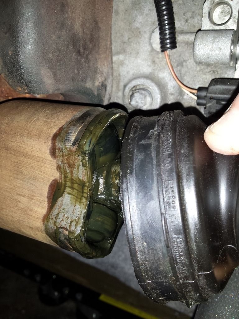 As can be seen the lower trilobe bearing is flush with the edge of the cup, now even with the amount of engine movement allowed by the standard engine mounts, the engine would probably never move enough for the shaft to pop out but i wasn't happy with it because it is designed to operate further in than this. (also this is with zero rear camber, the situation would be a bit better with 1 degree or more). After looking up the spec of the Focus shafts (the correct ones for the IB5, not the 2.0, ST170 or diesel) i reckoned they would be a bit too long and might bottom out on suspension compression and round corners, which is strange because the IB5 box is the same. Everyone seems to use the focus shafts so they must fit, but i already have these shafts and they are stronger. I read that the sonic requires spacers on the drive shaft and i had a look to see what i could get, i found some 4mm stainless steel washers on fleabay with the correct OD and ID. They are laser cut from 4mm plate so should be very flat. After some measurements it turned out that there would still be plenty of thread going throughthe hub nut and loads of splines engaged still with 8mm of spacing behind the shafts and the trilobes will be in their correct position in the cups at normal ride height. I ordered 4 of them, 2 for each side. In order for them to sit flat against the driveshaft flange i had to radius the inside of 2 of the washer to match the radius on the driveshaft, failing to do this would introduce a weakness at the narrow pressure point that would be introduced. 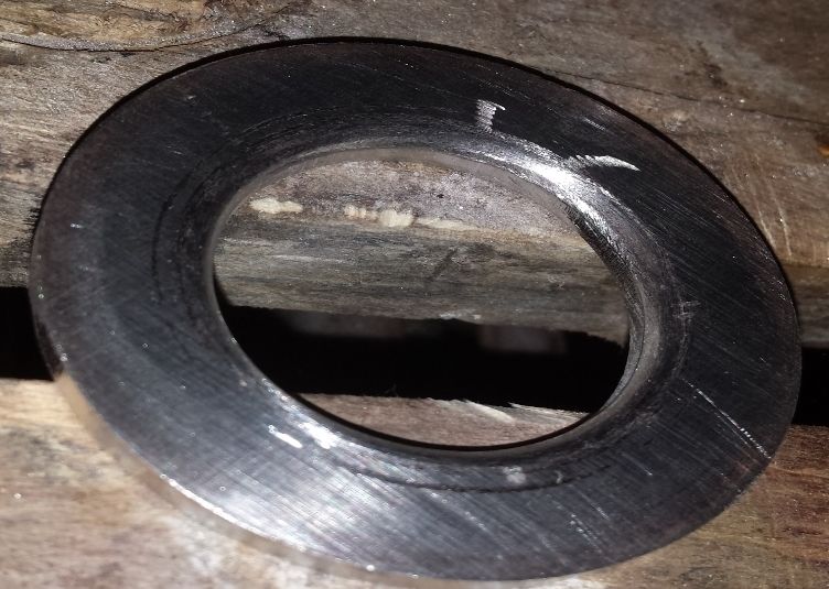 Here they are rested on the flange sitting nice and flush 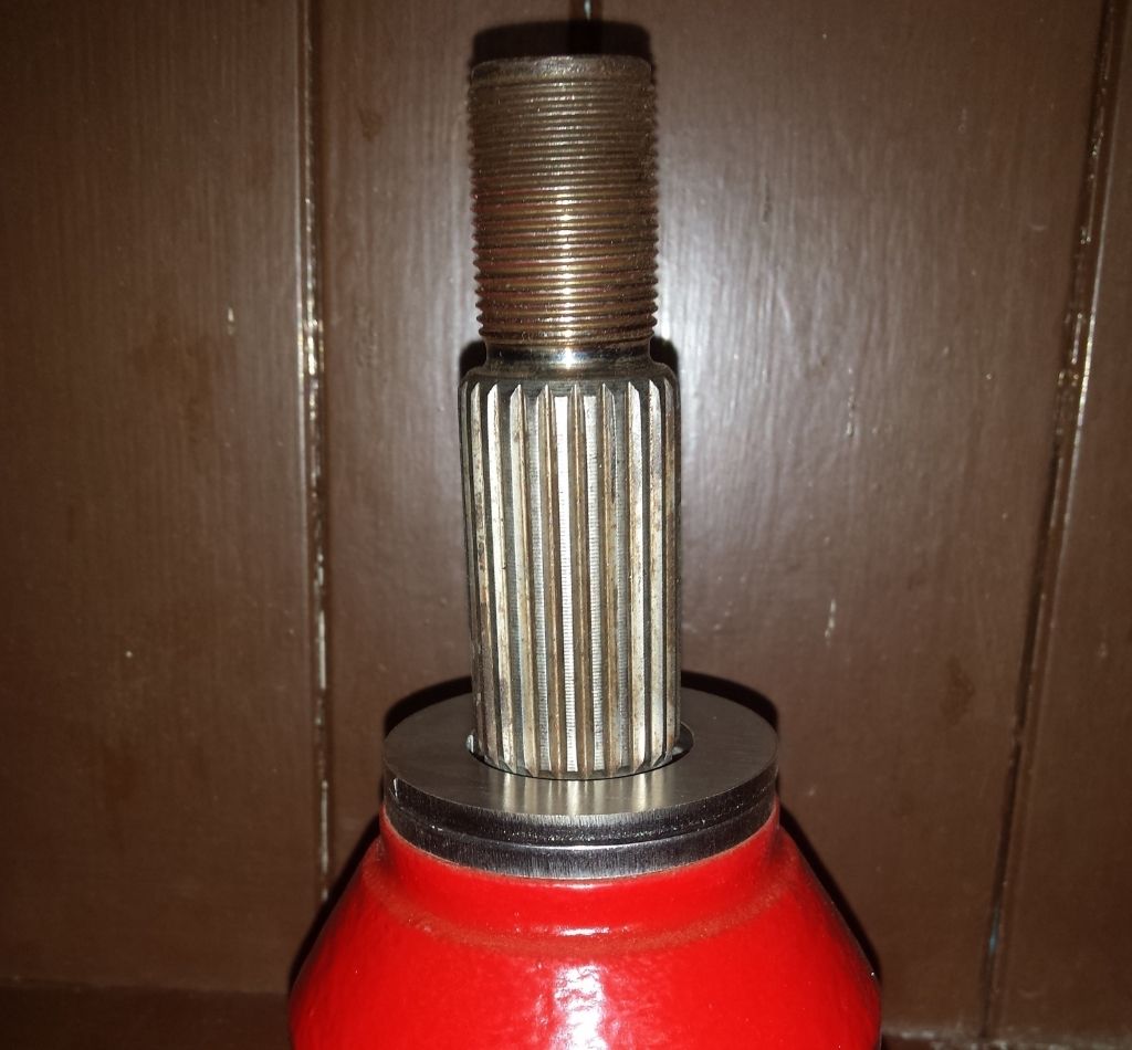 To hold them in place and stop them moving while i install the shafts i pushed some chemical metal down the gap between the splined shaft and the inside of the washers. 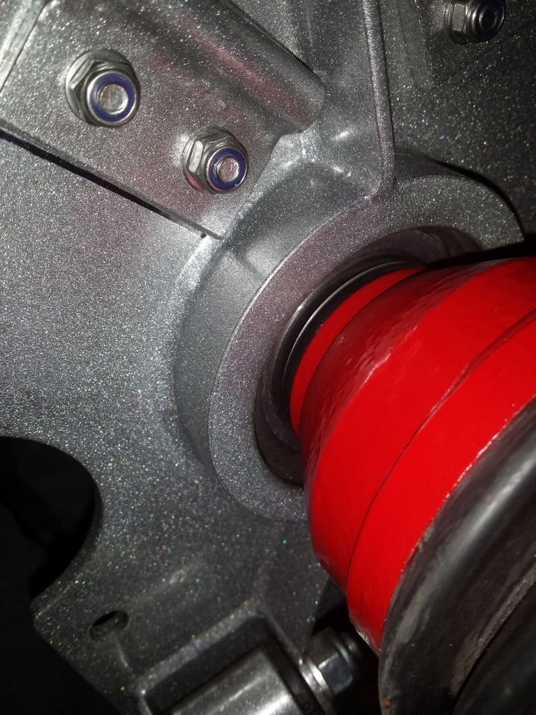 With the spacers fitted the shaft is now well inside the cup at full suspension compression: 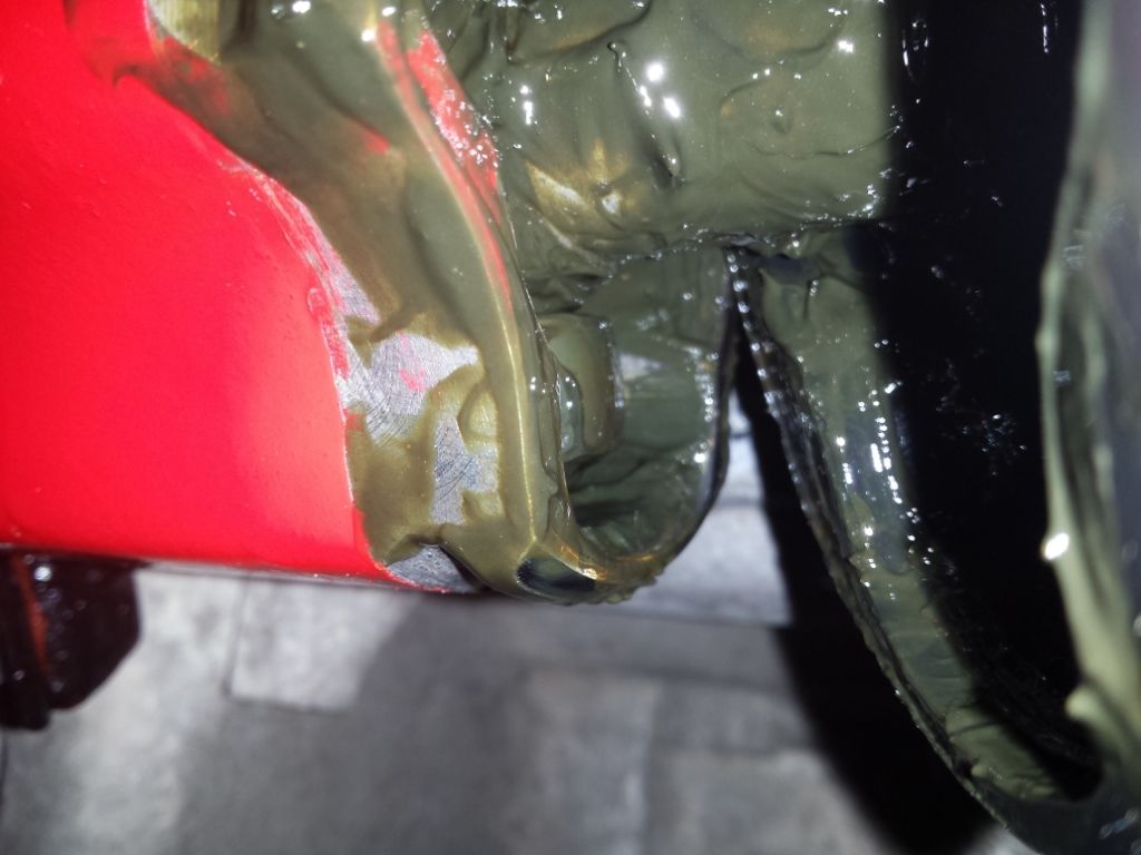 Here is the backend so far: 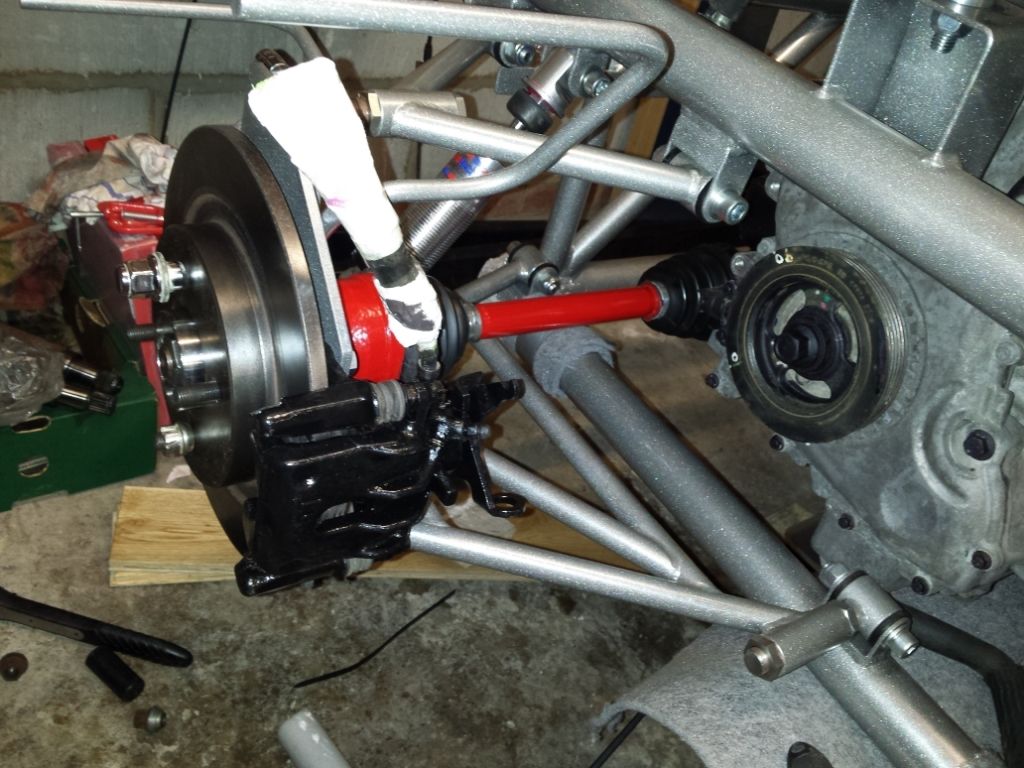 I have cleaned up, checked over, treated and painted the calipers and the driveshafts I have a 1mm shim installed behind the rear discs to solve the caliper alignment issue covered in a previous post. Wing stays and wings fitted but not bonded on yet. 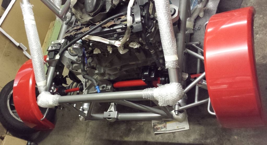 They have been measured up for use with 15 inch wheels and 195/50 tyres, i am not going to be using anything bigger than 15inch due to the significant weight increase and much increased rotational mass. My 15 inch Ford Puma propellor style alloy wheels weigh 14.4 Kg with Toyo Proxes T1R tyres. Those tyres are supposed to weigh 8.4 Kg and the tread is almost like new so that makes the wheel weight only 6kg which is quite impressive. To save any weight on the wheels i would need to buy OZ Ultraleggera 15x7j alloys at 180 quid each, from what i have read they seem to be one of the lightest available at only 5.2 Kg, they also look great. Its not worth the money, yes the OZ wheels are slightly wider so should be better for track use, (7j as opposed to 6j for the Ford ones), but you can buy a decent set of 4 Puma alloys of fleabay all day long for 100 quid and they look ok. I must point out that only the propellor style wheels will fit on the rear, the 9 spoke ones foul on the upright, they are the same dimensions, but thicker on the inside. Also a 7j wheel would probably need a wider tyre than 195, so heavier, so it might not be any lighter overall anyway. The Offset of the Puma alloys is ET34, Focus is supposed to be ET42 i think, does anyone know what the recommended scrub radius is supposed to be for the front suspension? What offsets are others using with 15 inch wheels? Should i start a thread on the technical section if there is not one already? |
|
|
|
Post by BobN on Mar 30, 2015 8:56:56 GMT
Looking good and you have some good information here.
Yes go ahead and add to the technical section so others could benefit. There might be some threads you could just add to or create a new one in the relevant area if not.
Bob
|
|
|
|
Post by duratec1999cc on Apr 5, 2015 22:56:39 GMT
Made some brackets up for mounting the exhaust silencer out of 2mm stainless steel plate: 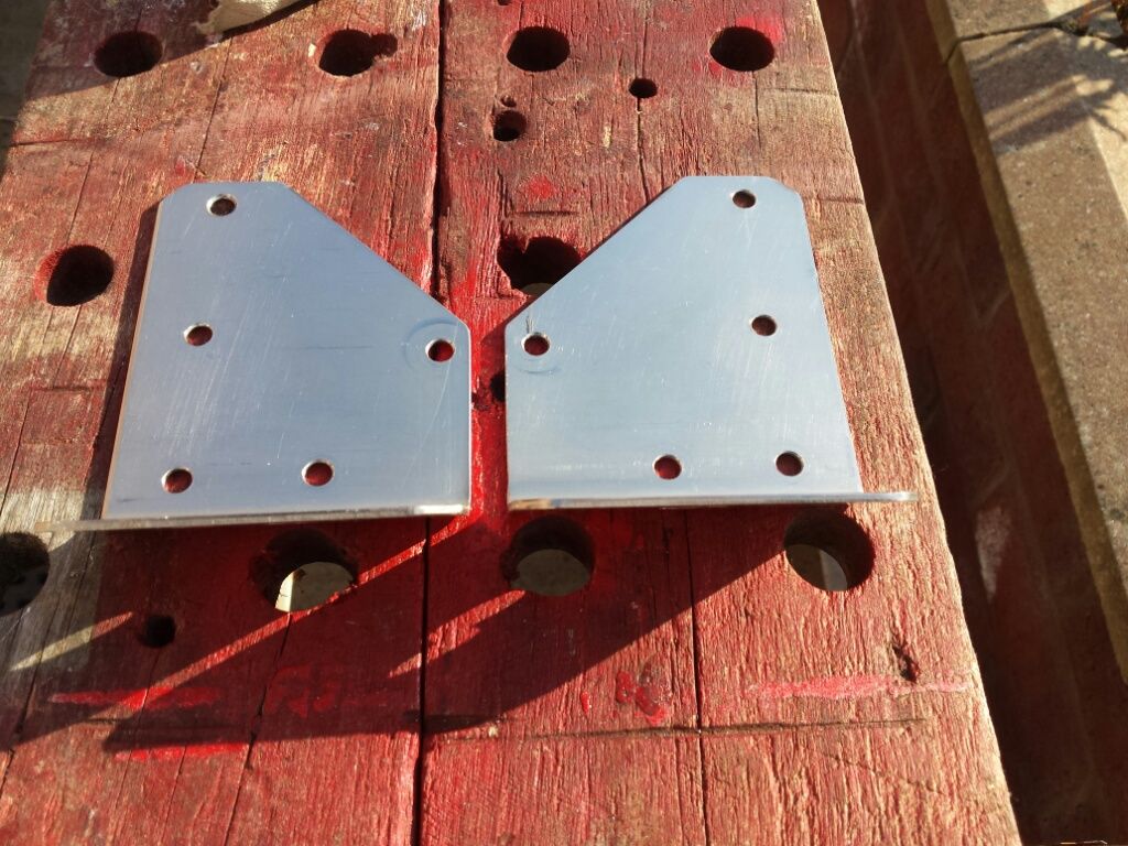 I considered bolting these right through the chassis tube but it would be neater to tap m6 ss bolts into the tube so nothing it protruding behind the tube. It needs to be quite strong so each one is using 5 bolts to secure it to the chassis. I am also going to seal and bond them with PU adhesive to prevent any water ingress: 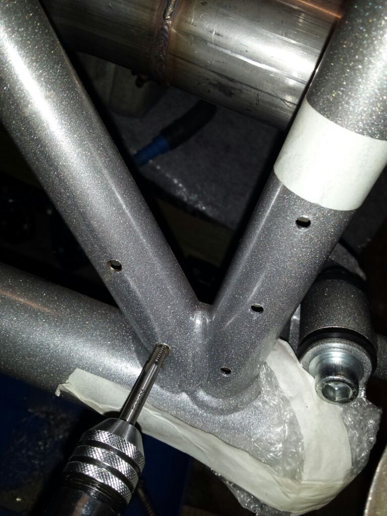 The tubes are thinner than i expected so the tap only managed to cut about 1 thread into the tube. Ill see how it feels when fitting them up tomorrow. the silencer will be mounted using the cotton reel type rubber exhaust mounts to provide some give. A flexi pipe in the exhaust would be better. |
|
|
|
Post by mattyp on Apr 5, 2015 23:12:12 GMT
Difficult to tap thin wall tubing, would rivnuts be better?
|
|
|
|
Post by mawdo81 on Apr 7, 2015 8:16:51 GMT
Tube is 2mm thick. A 6mm hole will take an m4 rivnut and id expect that to be much stronger than a tapped thread of m6 in the 2mm tube.
Sent from my GT-I8190N using proboards
|
|
|
|
Post by carlyd on Apr 7, 2015 9:15:56 GMT
Tube is 2mm thick. A 6mm hole will take an m4 rivnut and id expect that to be much stronger than a tapped thread of m6 in the 2mm tube. Sent from my GT-I8190N using proboards I have used M4 rivnuts on my chassis and they work well. Just make sure you fit them firmly or they spin when you tighten the bolt. |
|