|
|
Post by miket on Aug 17, 2015 21:13:29 GMT
Replacement calliper slider pin arrived so front callipers installed. I'm planning to use the donor front brake hoses so I need to make up brackets attached to the subframe for them. The subframe's 'hollow' there so it looks like a job for rivnuts. I'm planning to use 2 x M5 rivnuts on each bracket; installing just one initially so as to allow some rotational movement around it to help set the best position, and then put in the 2nd rivnut to keep it there.
The donor brackets had a distorted-hexagonal socket to hold the hose in a set position. I don't recall seeing anyone reuse or replicate these sockets on fabricated brackets so I guess spring clips must be enough to prevent the hoses rotating in the brackets?
|
|
|
|
Post by gwnwar on Aug 18, 2015 5:37:41 GMT
Just make sure the hoses don't rub with car down on the tires and turned lock to lock..
|
|
|
|
Post by miket on Aug 18, 2015 16:31:17 GMT
Yes will do - thanks. The donor front brake hoses seem to have a 'memory' of how they're supposed to stretch out and return - which is handy. Made a test bracket from thin ally and marked out some thicker stuff ready to cut n drill ... once my neighbour's in so I can borrow his pillar drill for the 16 mm hole for the hose ends  I'd planned to fix the brackets to the flat surface on the underside of the subframe, but the whole area is pretty inaccessible to drills with the suspension in place so it was more Dremel-clone abuse and holes through the seam on the top edge of the subframe. Anyone planning a build with donor front brake hoses - drilling for these brackets would be easier when the front suspension's not in place .You'd need to look at some pics to get the holes in the right area, but it doesn't seem to be critical to the millimetre. |
|
|
|
Post by miket on Aug 26, 2015 17:38:06 GMT
Made up some front brake hose brackets out of 5mm bar. 5mm is over the top, but I'd read of some flimsy brackets and over-compensated! I rounded off the corners but then regretted it because there'll be less metal under one of the 2 arms of the clip. Doh! 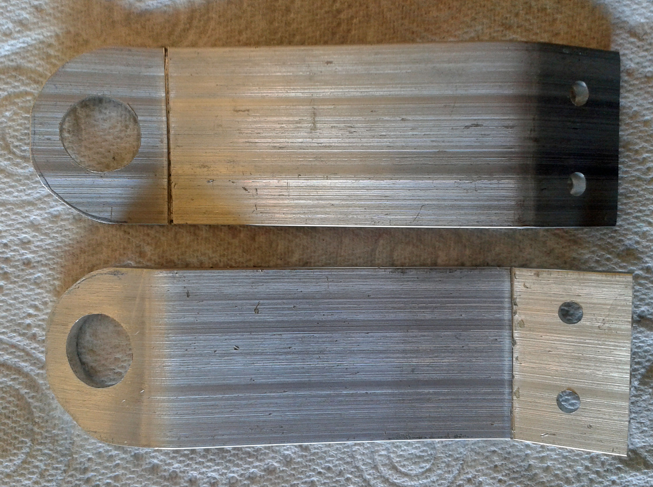 With no room for a Mk1 1.6 airbox I'm moving to 'universal' cone filter setup. I plan to add a 'heat shield' .. partly to keep the direct spray of water from the front wheel out of the filter! Had some trouble tracking down an adaptor for the AFM so, in case it helps any other (UK) builder I found Green Air Filter Universal Top Hat Adaptor GREAA02 ... seems like a really sturdy bit of kit, fit's nicely and came with a rubber gasket. Knocked up a little bracket to secure the AFM to the chassis:- 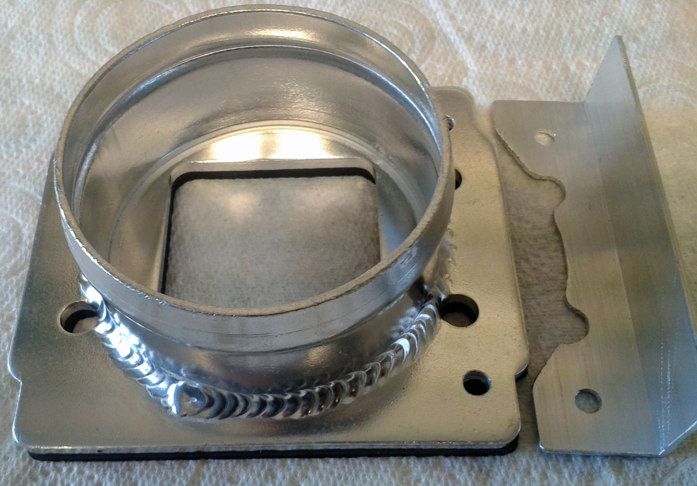 Just need the short pipe to arrive and then I can tick off another job. |
|
|
|
Post by miket on Aug 30, 2015 12:17:16 GMT
Front brake hose brackets (5mm girders in this case) for donor hoses installed and hoses not rubbing. Also installed the improvised expansion bottle a la Lukiez 'cos the donor one would have to have been on left bulkhead and let's face it it's not pretty:- 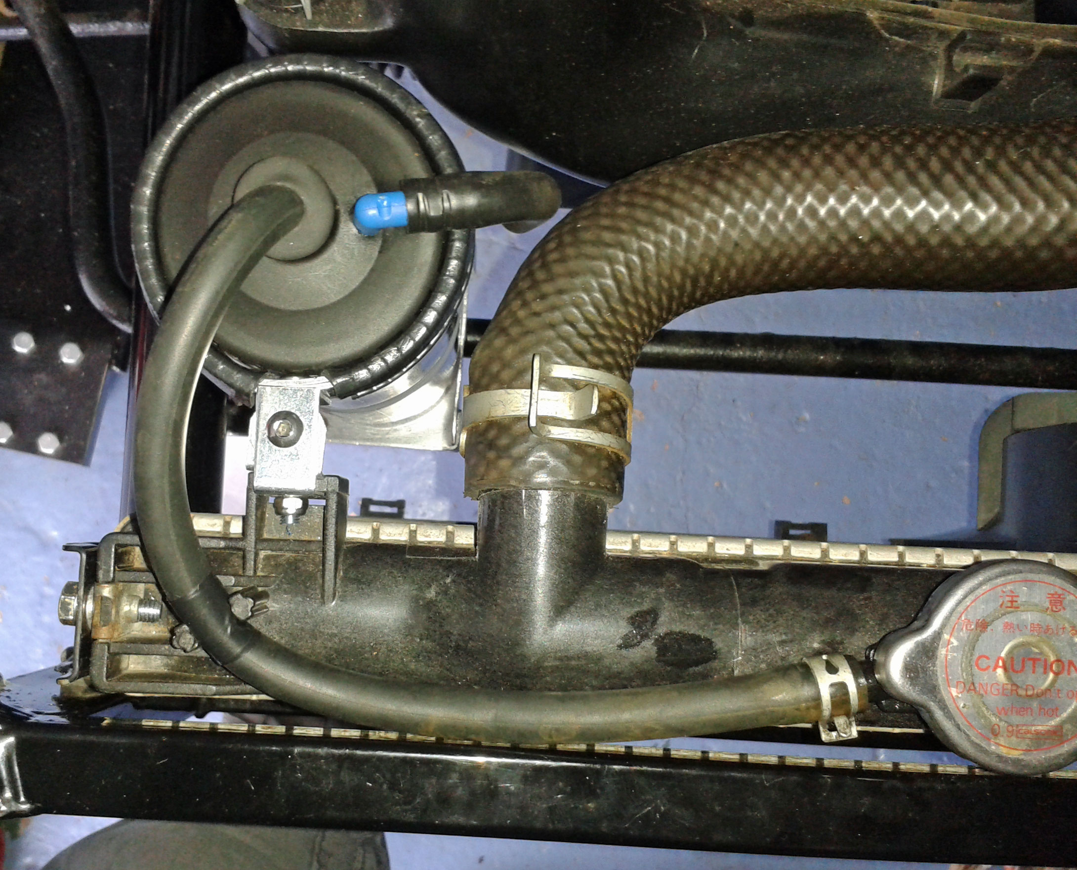 I've got a couple of issues to sort out with the air induction / cone filter... here's the closest this budget-build thread is likely to get to car-porn - some red & shiny bits at last:- 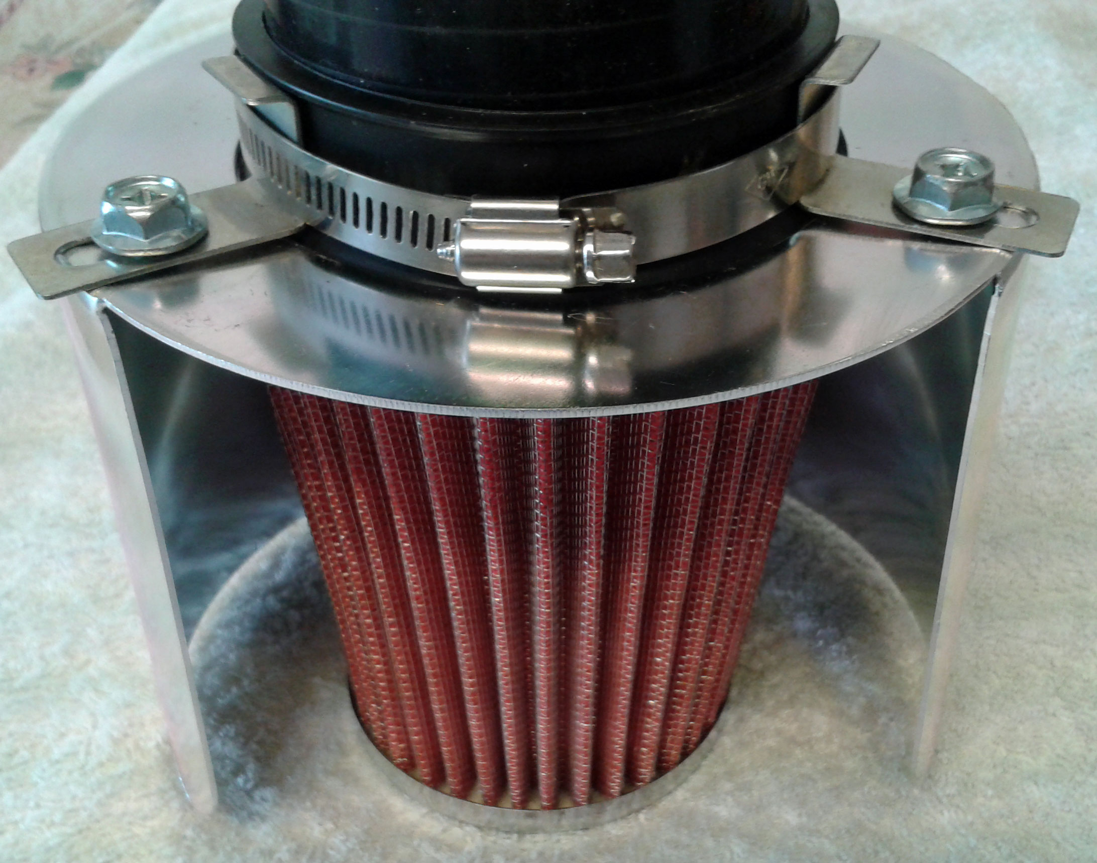 The pipe joining the AFM adaptor to the filter usefully has the right ID to fit over the adaptor and the right OD to fit in to the cone filter, but that then makes the filter connection rubber being jubilee-clipped on to rubber. Further, the 3 brackets for the heat shield then push the unsupported rubber into a rounded triangle of potential leakiness. I'm thinking of making a strip of ally in to a circle to put inside the pipe for the jubilee to clamp the 2 layers of rubber down on to, but if there's a better way or any other induction-tips for a first timer it'd be appreciated. I thought the adaptor looked good so I drilled it for a bracket whilst waiting for the pipe to arrive. Now I have the pipe and come to put bits in place it's apparent that the adaptors holes are too close to its weld for AFM bolts's nuts to seat properly. The bolts will also be so close to the pipe wall that they may stop it pushing all the way on:- 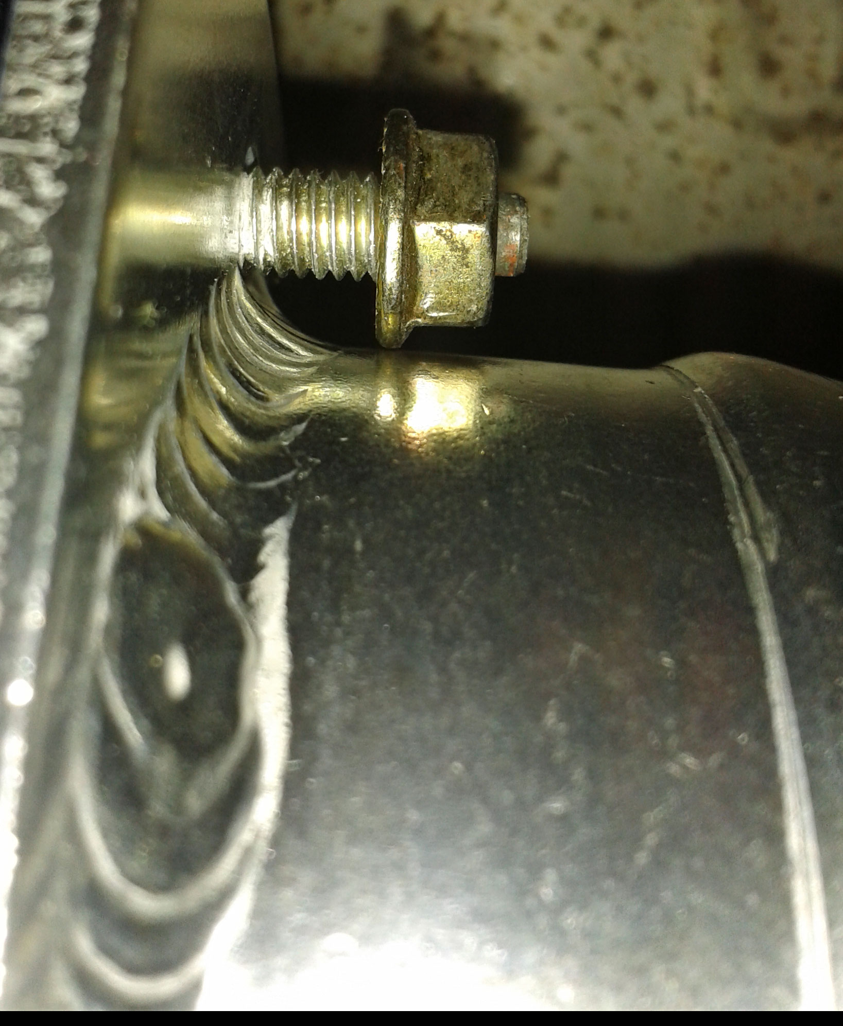 I guess I'm going to have to file off some weld around the bolt holes for the nuts to seat, but I've not done any welding so aren't sure what the likelihood of going right through is. Then I'll have to shorten the bolts as far as possible to allow as much pipe as possible on to the adaptor. I also need to find if people seal air induction component joints with any sort of sealant to prevent unfiltered air leakage. |
|
|
|
Post by gwnwar on Aug 31, 2015 5:27:59 GMT
I wouldn't worry about unfiltered and much as unmetered air..
|
|
|
|
Post by miket on Sept 5, 2015 9:55:19 GMT
Trying to file the AFM adaptor's weld to allow the nuts to seat properly wasn't going well, so a good neighbour milled the weld around the holes for me:- 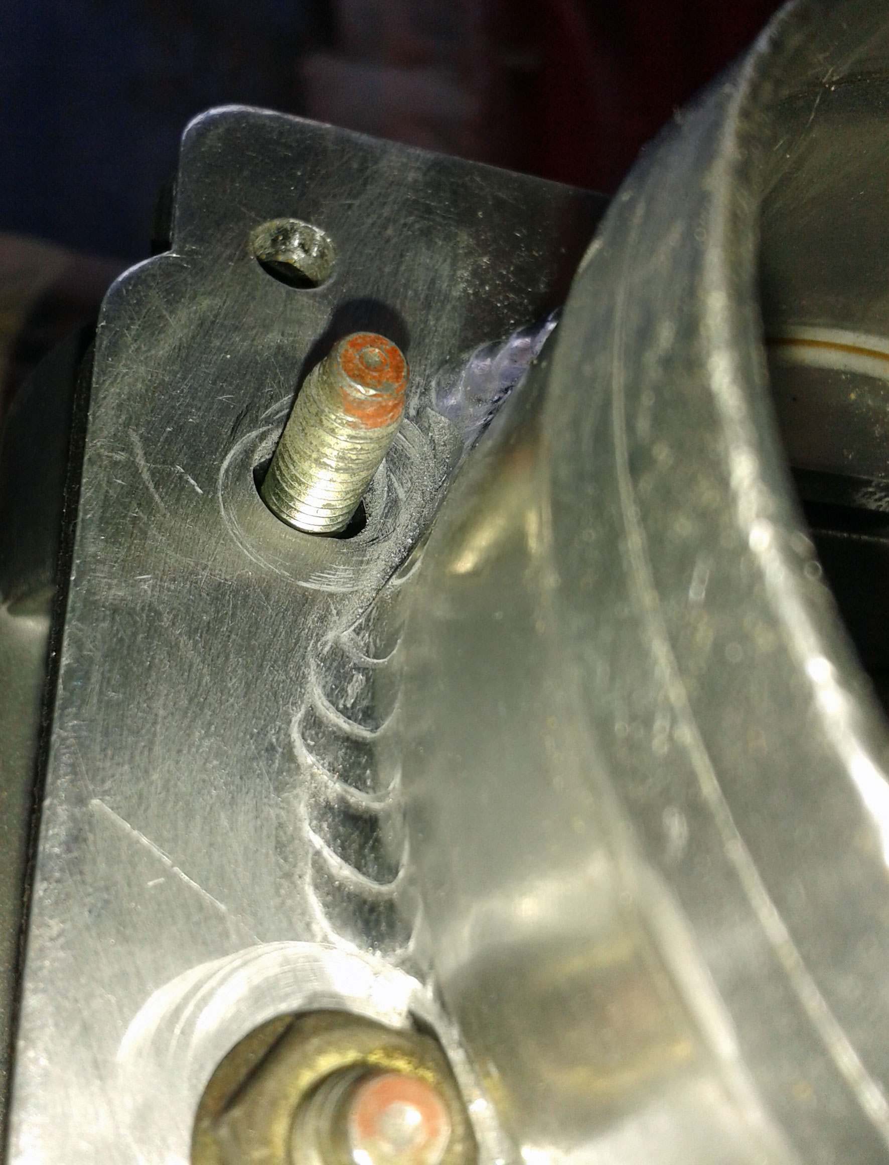 This still left the issues of the thickness of the pipe wall fitting between the bolts and the adaptor, but with a move to nylocs and some encouragement it fitted and allowed enough room for the jubilee clip to do its work:- 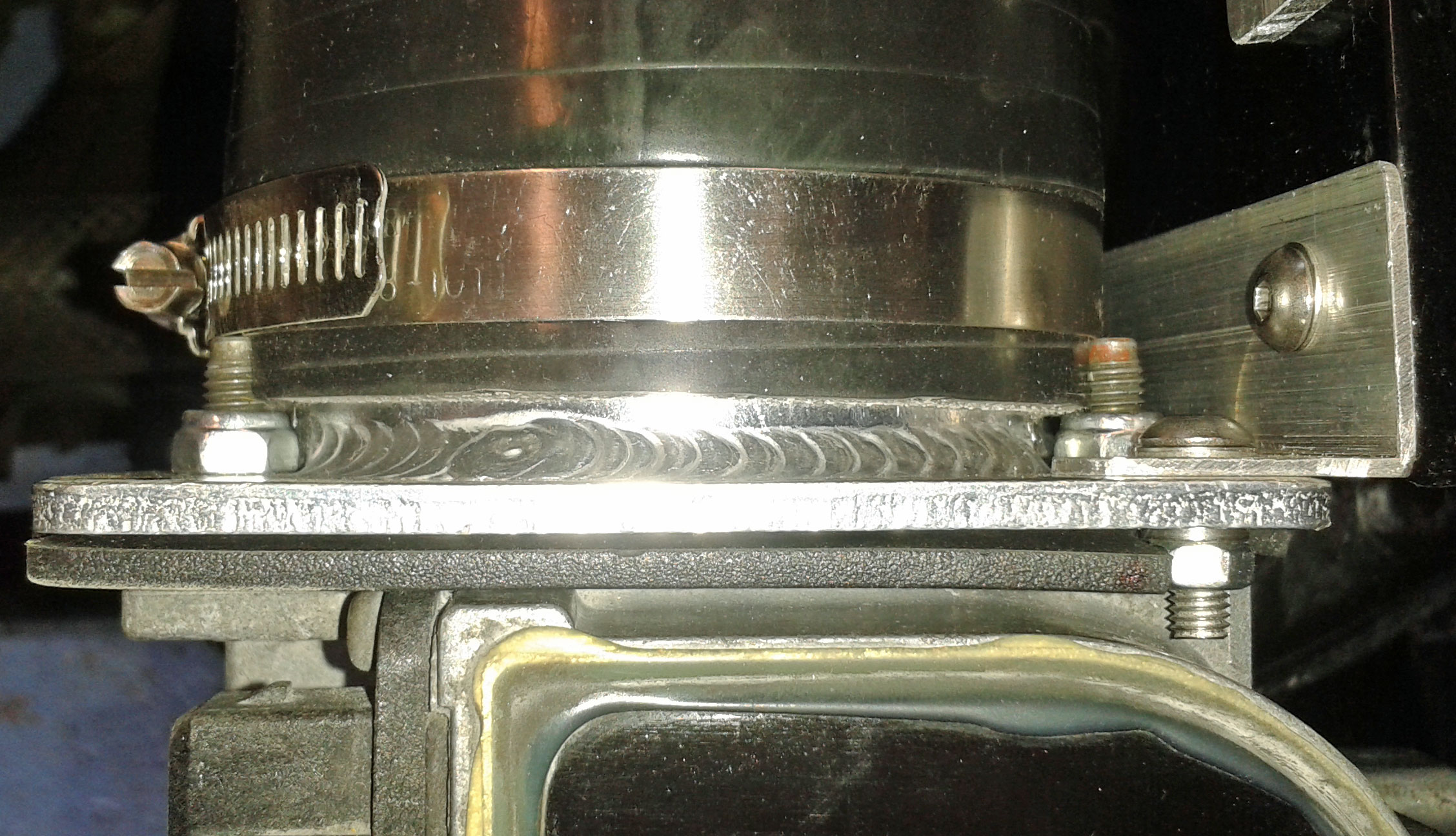 So that's Mk1 1.6 'air' sorted out with AFM adaptor, 15 cm of "3 inch" pipe, a universal cone filter and a shield:- 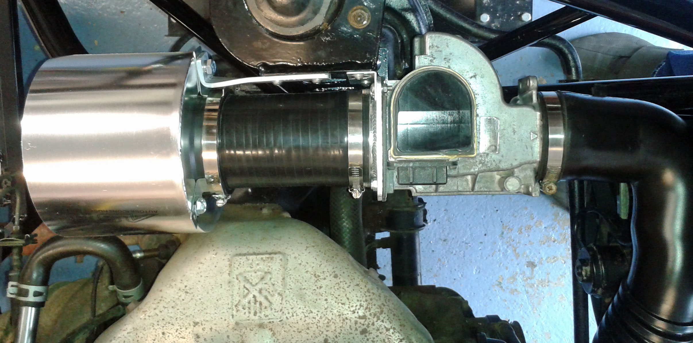 So overall the AFM adaptor I bought worked out okay, but needs its weld milling around the bolt holes for good results. |
|
|
|
Post by miket on Sept 9, 2015 17:47:01 GMT
Decided to install the (donor) seats to get a better idea of battery locations - and play cars a bit. Previous threads note the 'donor passenger seat' conundrum: it doesn't fit with the seat adjuster plastic cover on, but there's too much sharp metal for passing seatbelts over without it (re. IVA). I recall one build contemplating a 'scoop' in the side panel to allow more space and a few threads that binned the adjustment mechanism and replaced it with 'fixed' L-shape steel. There are other recommendations around moving the slider on one side forward a slot or two to help angle the seat some. I've decided to start off with a half-way house - trimming the adjuster plastic cover away at it's deepest back to the smooth metal insert that's behind it:- 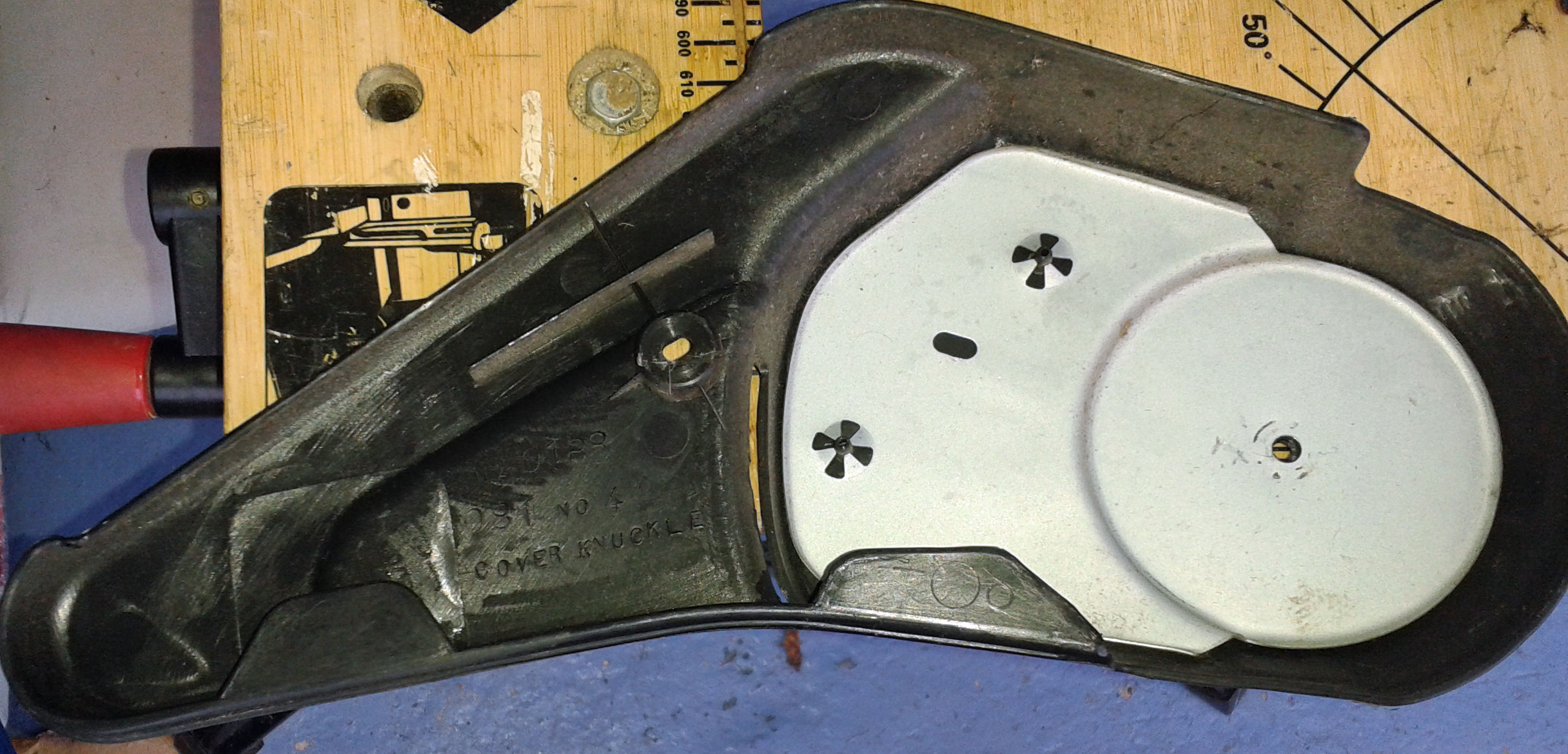 That leaves it quite a few mills thinner but still with a smooth firm outer:- 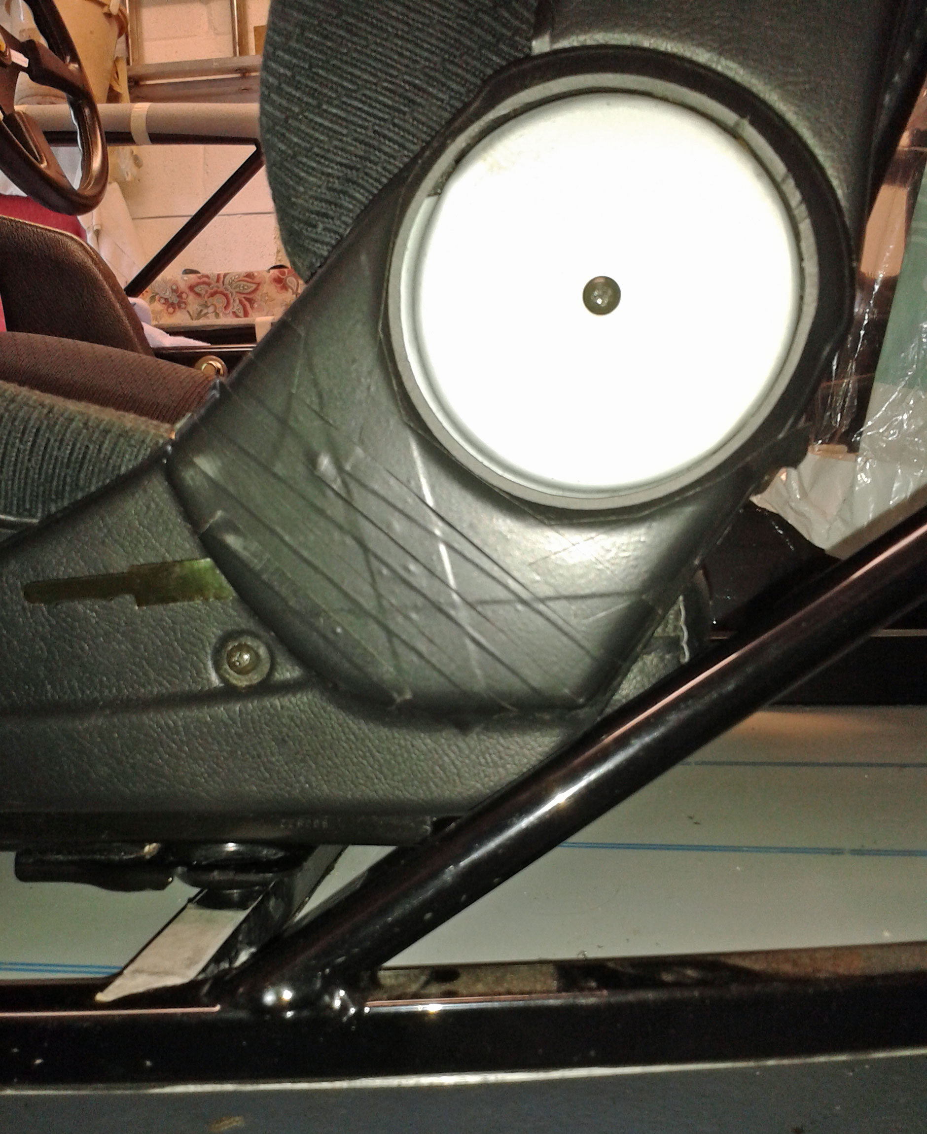 This allows almost a full range of movement, but makes eventually contact with the diagonal tube as above. The outer part of the seat will still need some fettling of the side panel if I keep it this way. If it gets palaverous I'll revert to fixed position and steel bracket. I need to have a read of the IVA about seat mechanisms - partly to find if running in to the chassis is a valid stop mechanism (!) or whether I need to put a bolt through the slider rails perhaps. Started to look at filler cap options. In line with my budget build principles I'll use the donor parts, but plan to explore a top entry rather than side entry. Dog bowl related plagiarism may ensue. Useful to find that the universal cone filter's neck reducers make good neck reducers of a different kind too:- 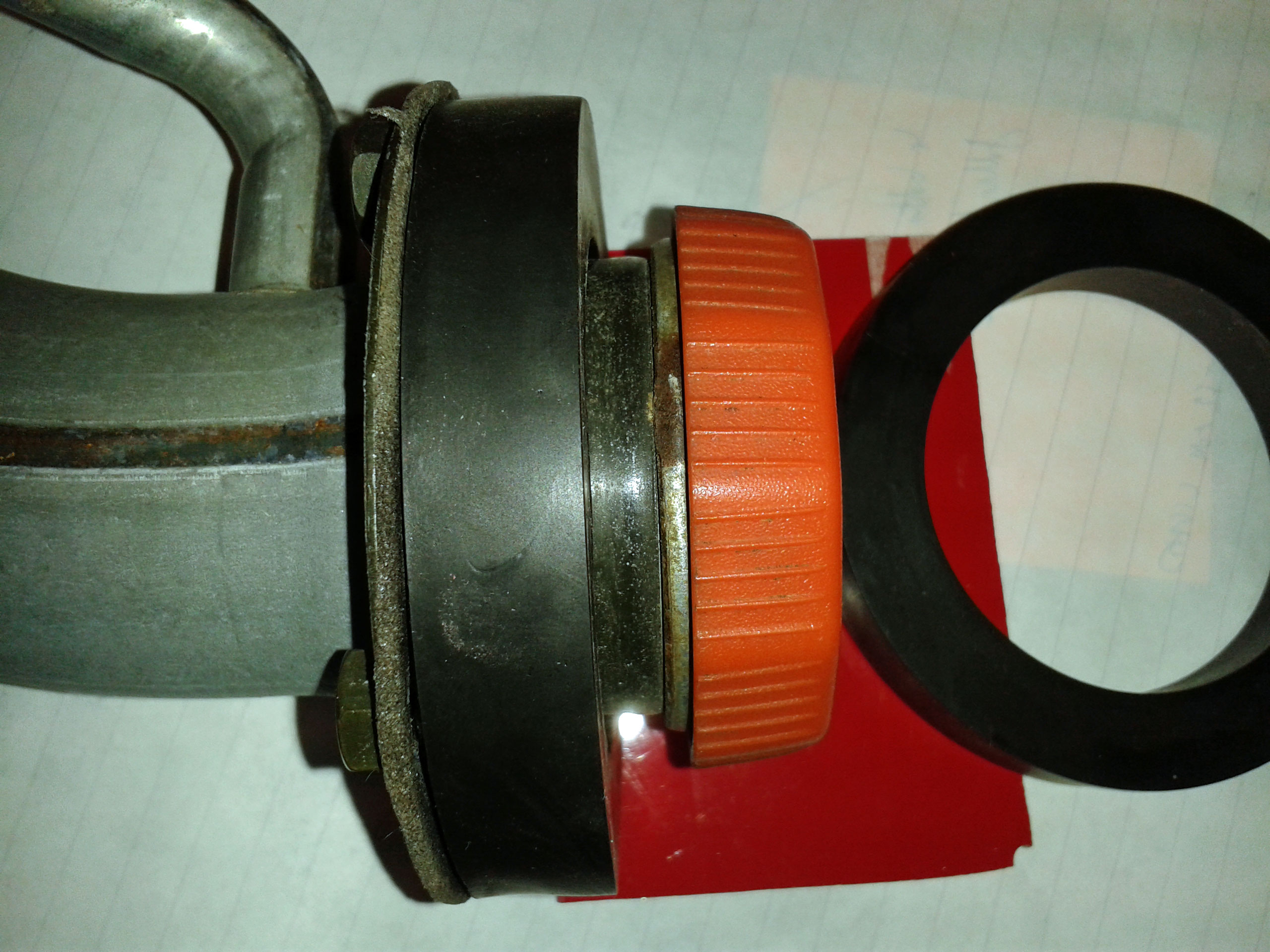 ... might come in handy for reducing protrusion and allowing some shaping to fit the contours of the tank cover. |
|
|
|
Post by jgilbert on Sept 9, 2015 22:31:26 GMT
Like the seat solution. I used fixed incline seat (fibre glass) but with seat sliders. The back stop for mine being the diagonal frame. Not a problem on my IVA.
|
|
|
|
Post by miket on Sept 12, 2015 8:34:03 GMT
That's good to know - thanks. Took a closer look at installing the fuel filler as the per the build guide using existing donor parts, but found it means putting a lot of sideways tension on the hose/pipe joints. With more experience I might be confident of the wonders of the jubilee clip to cope, but given that the pipe would be below the top of the tank and so potentially have fuel sitting in it I'm wary of going down that route. It would also mean losing space where the tubes for the rear lights would be going. I'd prefer not to top mount - so as to keep the clean lines up top - and if I'm going to use the donor filler inlet then it's not one for putting on display - so currently planning to locate the filler here instead:- 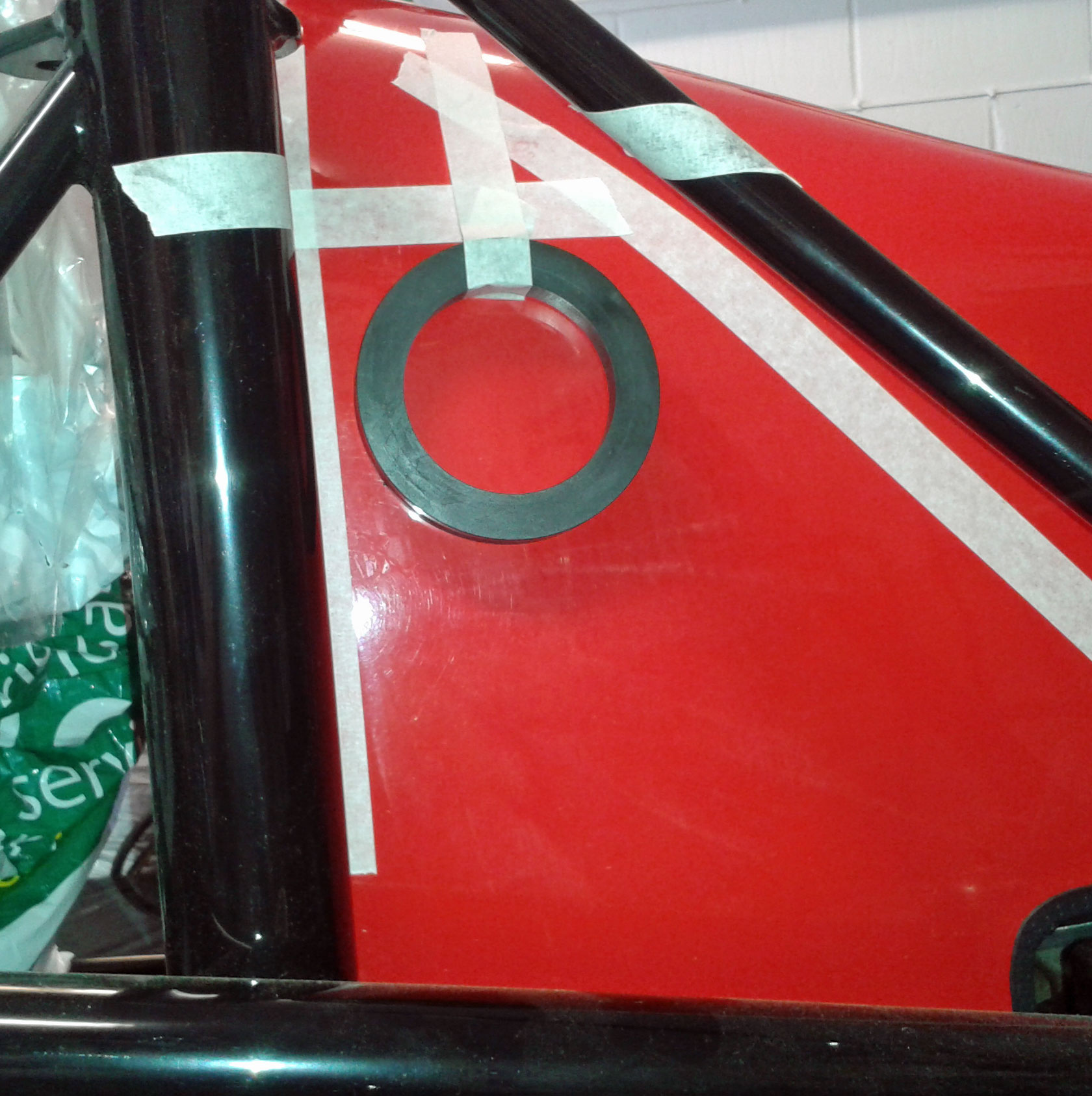 It's at this point you find out how much fuel-proof hose costs, but I think I can do it with a 90-degree bend on the tank, part of the donor metal pipe and 500mm of ultra-flexible hose from CBS. This'll give me a full tank and the opportunity to retain the table-tennis-ball valve in the donor pipe. Any words of experience on this welcomed! |
|
|
|
Post by gwnwar on Sept 12, 2015 17:25:52 GMT
I would get the hose and pipe before cutting the hole.. make sure you can get from point a to b..
|
|
|
|
Post by miket on Nov 18, 2015 17:34:59 GMT
It's been a while but I'm back in the garage. Picked up where I left on with:- 1. Making an ally battery box - partly because I want somewhere to locate a basic battery isolation switch as well as tidying things up some. Means putting some eyelet terminals on the battery cables and I'm going to try my hand at soldering rather than crimping (there seems to be internet arguments over which is best), but I don't have a crimping tool on that scale. 2. Decided on my fuel filler setup and cut the hole in the tank cover - no turning back! I'll post some pics when it's done, but it's placed as proposed above and uses CBS 51mm/2" ultra-flexible to join to the tank. My remaining concern is whether the hose needs any support under its midpoint to take some weight and stop it flapping around, but it's light and will be largely empty. Along the way I also considered the MEV-guide approach - but found it a bit strained as well as settling for a part-full tank. Also looked at going straight up from the tank to the top rear left of the tank cover. This looks like the best option for a workable/simple approach as it only needs an 'elbow' hose and would be relatively easy for taking the cover on and off,... but then it means the filler cap is there on display for all to see and would lead me in to big spending on shiny new aero filler caps. When looking in to this the 'fluoro' elbows looked (relatively) reasonably priced, but I also read they aren't for use immersed in fuel ... which it would be whilst the tank was full. I'm sure there's opinions both ways on this. The CBS 51mm/2" ultra-flex is an easy fit on to the tank, but CBS also do a spiral clip which works around the wire in the hose and holds it well. On the fuel filler neck/pipe the hose is too loose, so I used some of the donor's plastic fuel filler pipe as a gasket between the metal neck and the ultra-flex hose. I had to unpick some of the spiral wire to get the hose on to the gasket and fixed it with a standard jubilee clip. The ultra-flex hose comes with evidence of suitability for the IVA. I also got some of their fabric covered hose for the smaller hose ('cos it was the only one they had with the correct ID) - this had markings on it but they were illegible so I asked CBS for evidence of its suitability and they sent something through bless 'em. I also started to unpick the tape off the wiring with a view to improving it's flexibility for placement and to do some loom trimming later. Along the way I found the following three things where I need to work out what they are - I'll be researching later but if anyone knows off the top of their head I'd appreciate it to save some time:- 1. This thick black wire runs along with the Heater Fan Switch wires and is marked "AVS 3". If I'd known what to label it with when I stripped to donor I'd have labelled it, so I think it must have been like this already .. could be wrong. No terminal on the end of it so presumed already broken. 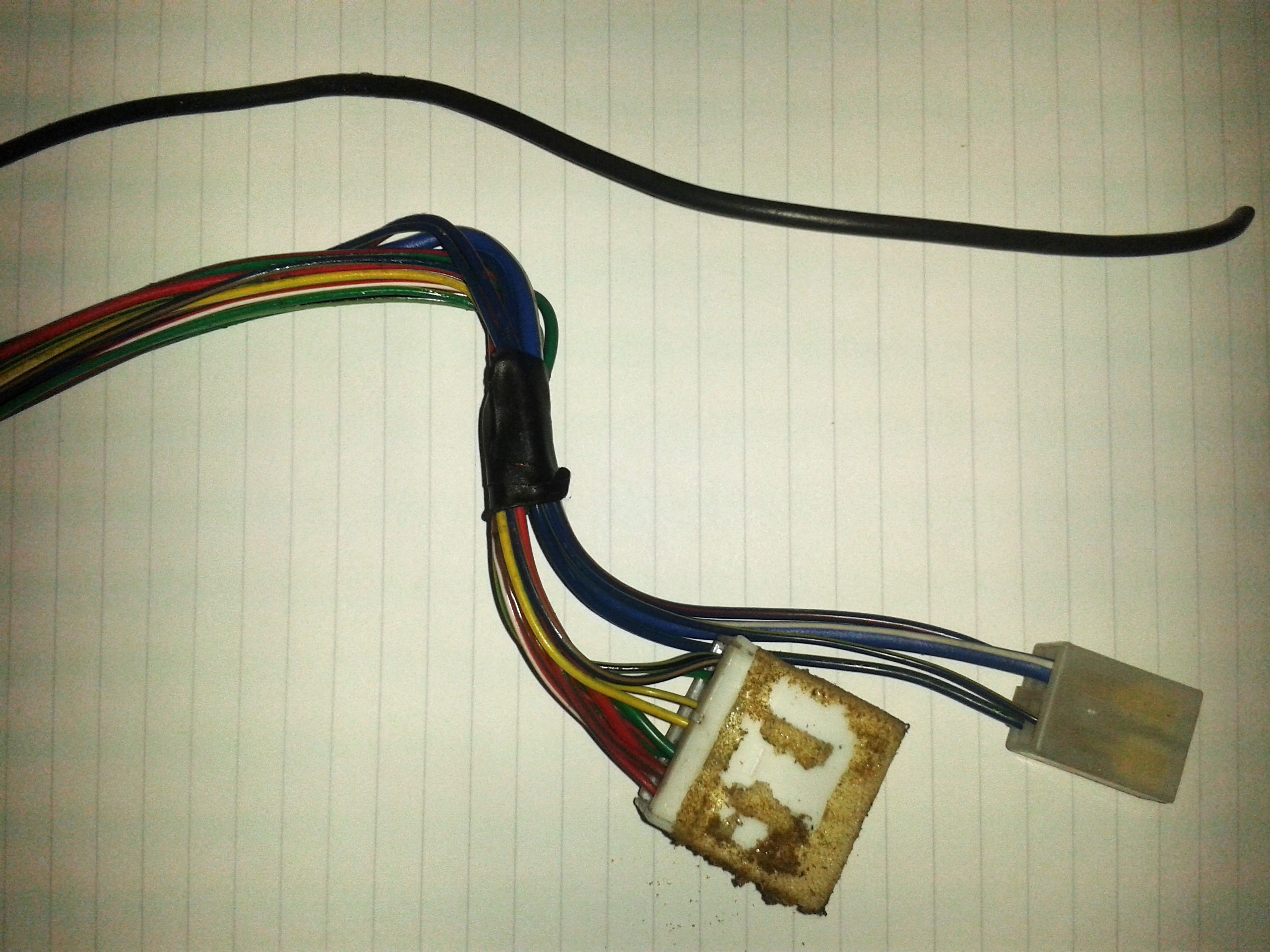 2. This black wire runs along with the wires to the Fog Lamps switch and the Light Dimmer. Again unlabelled so presumed already broken. 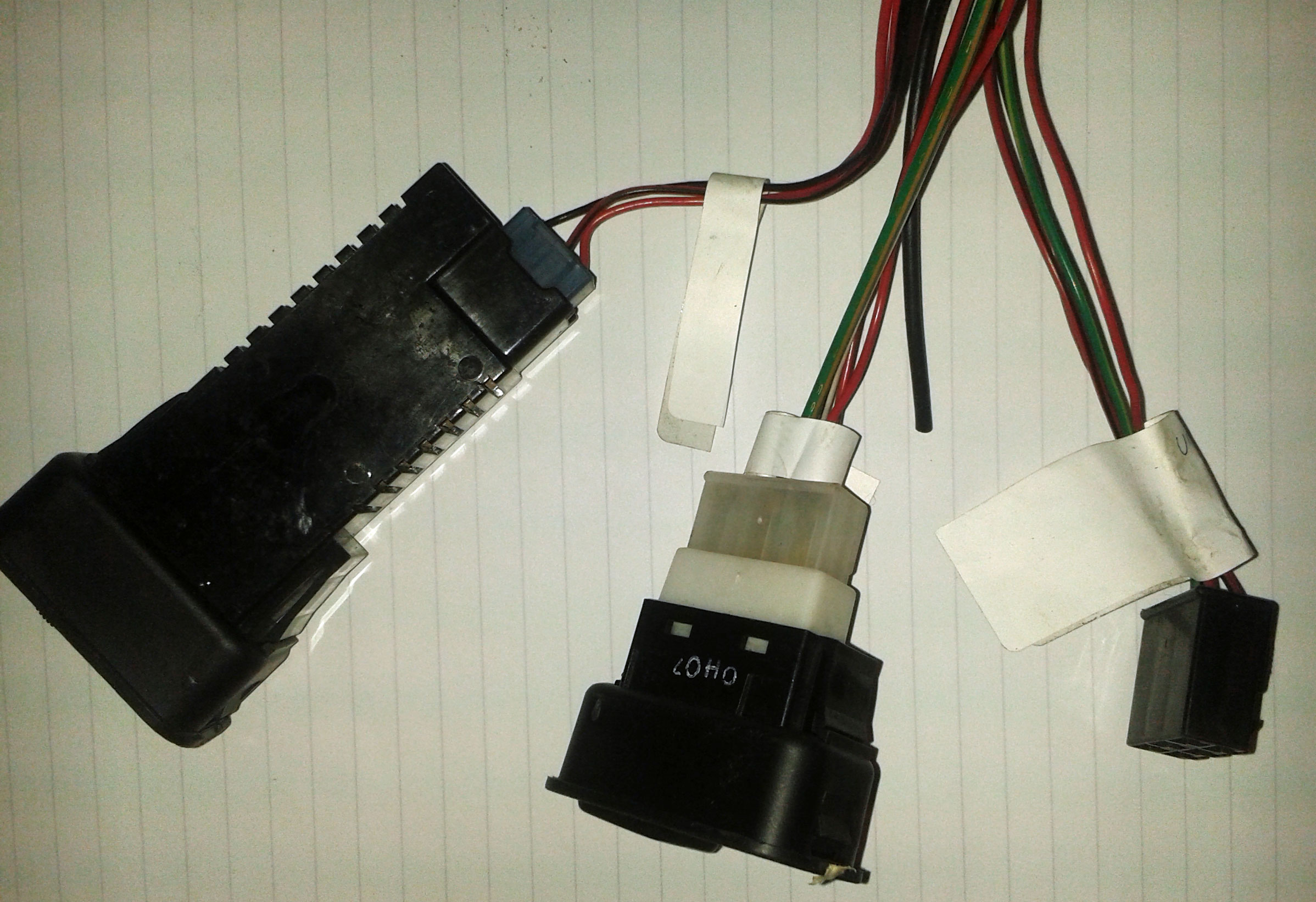 Would it be dangerous to assume any such loose black wire as these can be attached as an earth/ground? 3. These 2 fellas hang out near the dash courtesy light. They are blatantly unlabelled and I'm duly ashamed of my failure to label properly:- 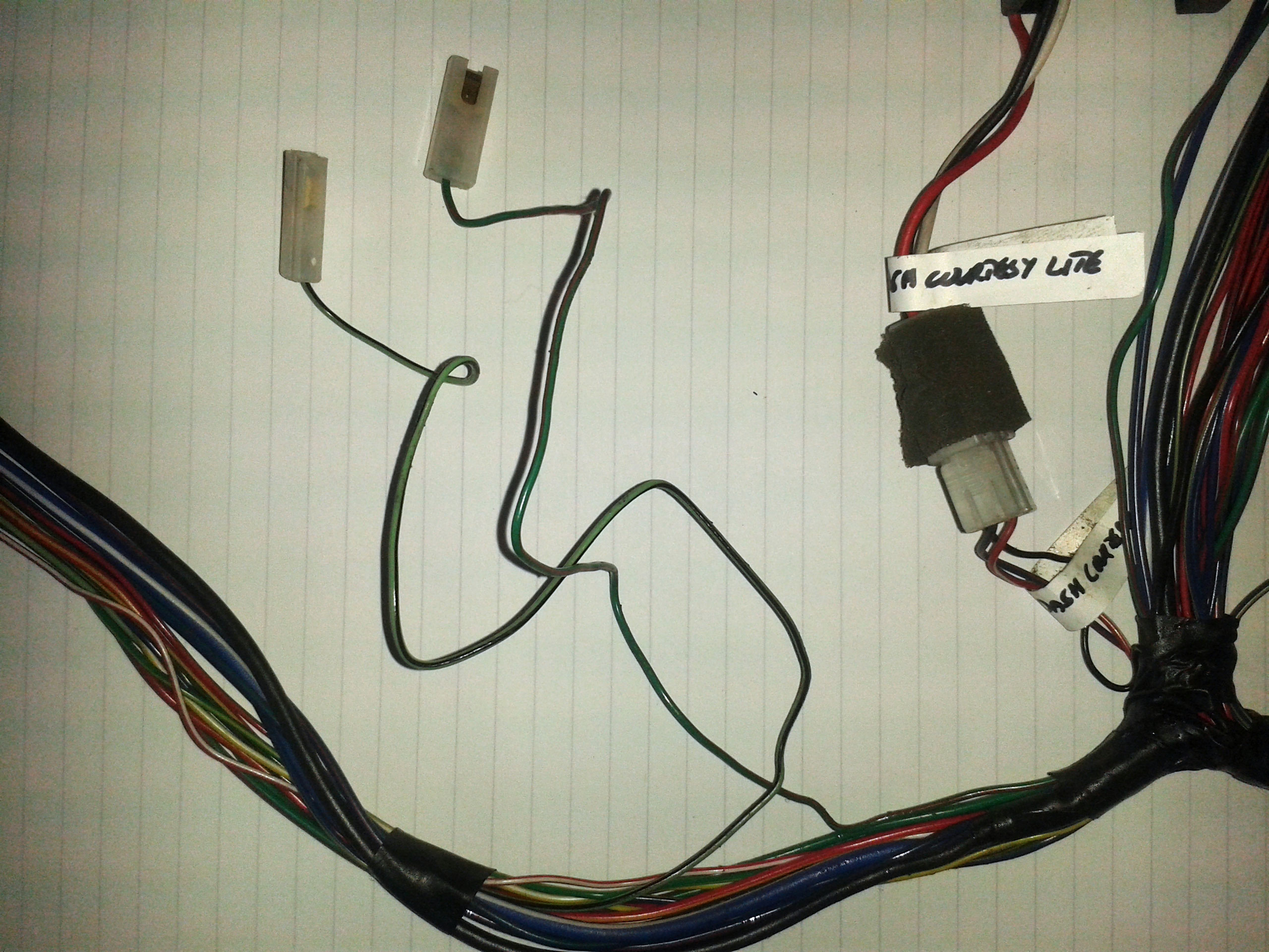 Hopefully soon have fuel and battery sorted and be approaching a first engine start. |
|
|
|
Post by gwnwar on Nov 19, 2015 17:55:35 GMT
I have used a bench vise to crimp battery cable ends then used a dull chisel long ways to dent the end crimp..
All black wire should be grounds..
|
|
|
|
Post by miket on Nov 24, 2015 15:11:26 GMT
Thanks - looks like I knew they were grounds when I cut them from what must have been seized fixings - lesson learnt! As mentioned in a specific thread - I've been trying to get hold of the right size eyelets for the +ive battery cable - should have been straightforward, but the sellers listings were (accidentally) misleading and I'm pending on replacements. I'll note the right size on here when I've proved it! Tried to spray my fuel filler cap to match bodywork, but the spray-can was duff... it's been that kind of a week. Got my filler neck mounting holes done, but after worries about gelcoat cracking I'm now concerned about whether I'm asking too much of GRP with 6 mm holes in 3 to 5 mm thick GRP that are only 5mm from the neck-hole edge. Especially as I'll have flexible hose turning a corner from it so applying some sideways pressure. 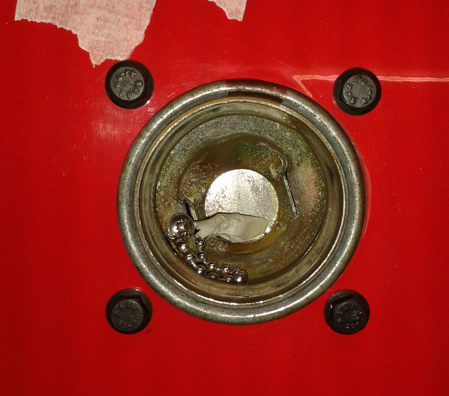 I've got some support bonded on the inside that also reduces the amount of neck sticking through:- 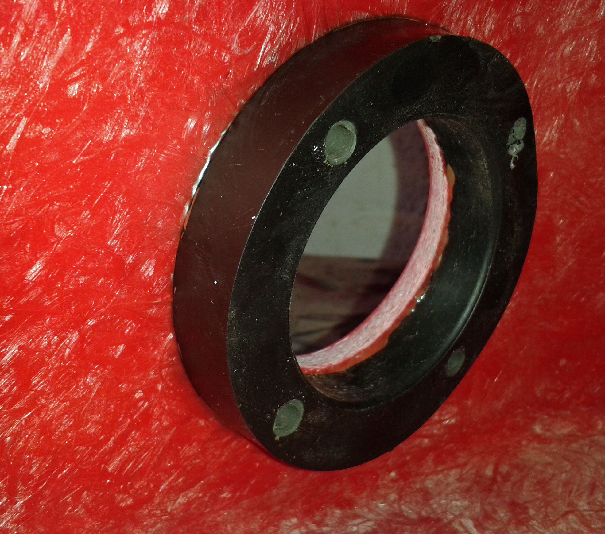 Might need to look at bonding a metal escutcheon on the outside? |
|
|
|
Post by miket on Nov 29, 2015 17:38:19 GMT
Decided to try making my own ally (flooring) escutcheon to epoxy on to the grp around the fuel filler neck to strengthen it.
Replacement battery cable eyelet terminals arrived and they're a good fit for the +ive cable.The supplier has them listed as "Dim mm-squared = 16-25" and they're marked with "25", but I can't see anything about them that's "25" apart from my 6.5mm diameter cable core converting to .25 inches. Moral is to talk to the supplier first 'cos there's too many ways of measuring and describing these, and then suppliers can (appear to) screw those up too.
With the battery cables soldered I moved on to the rear plastic cockpit bulkhead so I can get final positioning for my battery box and cable entry point. It's quite a complex shape with few right-angles to work from so I decided to do a cardboard template - or more precisely one for each side initially. If I were to start over I think I'd cut out the basic/whole rear bulkhead before the chassis was mated to the ppf and then add any necessary holes later.
|
|


