|
|
Post by R2S on Jun 15, 2015 13:59:08 GMT
Oops, stripped the crankshaft pulley down thinking it would only go back together one way and now discovered I am wrong, the back plate (one with triggers for crankshaft sensor) fits back either way (indented face to front or to back) anyone know correct way (not obvious from manual and triggers are in different place depending which way its fitted).
Should say I took it off to get at timing belt etc and it was in such a state (solid mass of rust) I thought Id strip it and clean (should have paid more attention on strip down).
|
|
|
|
Post by Stewart on Jun 16, 2015 12:36:09 GMT
I think it rubs if you fit it the wrong way.
|
|
|
|
Post by R2S on Jun 16, 2015 15:02:25 GMT
I think it rubs if you fit it the wrong way. Did myself a dis-service when I came to put the pulley together I had marked the trigger plate just left it too long between dismantling and building and had forgotten. Indent does indeed face front. |
|
|
|
Post by R2S on Jul 13, 2015 20:25:27 GMT
On the last stretch before i start putting all reconditioned items together and fell for a real novice mistake today - I include it so that others dont fall into the trap. Was setting up the timing before a strip down of the front of the engine to replace the water pump. Started to crank the engine clockwise, easy to turn until about 3/4 turn when thing locked up. Managed to turn back and tried again ~ still locked. Now I know from snowbird1 its an non interference engine but just in case I checked all the valves and they were moving freely and cam timing was ok. Engine was running fine when I stripped so couldn't work out what it was. Checked rear of crank whilst turning and nothing appeared to be catching so assumed something was stuck in sump. Was about to strip bottom off engine but thought Id stop for a brew. Whilst thinking things through I wondered if the flywheel bolts might be the problem (flywheel is off but bolts are in end of crank for safe keeping). Removed the bolts and ~ you guessed it ~ everything was free It appear that by screwing in the bolts beyond their normal depth they had allowed movement but eventually stuck against something behind the crank end plate (hope I haven't done any damage!). So my advice to anyone stripping down MX5 is to remove the bolts rather than keeping them in the end of the crank. Read more: mevowners.proboards.com/thread/4319/deborah-build#ixzz3fnykHMou |
|
|
|
Post by R2S on Aug 6, 2015 22:23:36 GMT
|
|
|
|
Post by snowbird1 on Aug 7, 2015 6:32:37 GMT
Nice find, although the 1/8th NPT to 8 mm is more suitable, now if you can find a 'T' one for the thermostat housing!
|
|
|
|
Post by john on Sept 23, 2015 21:36:03 GMT
Started to de power my rack today, looking at the mk2 rack and seems once you remove all the bits and bobs its just the two pipes that need cutting and looping.
Is that right ?
|
|
|
|
Post by R2S on Sept 23, 2015 22:28:19 GMT
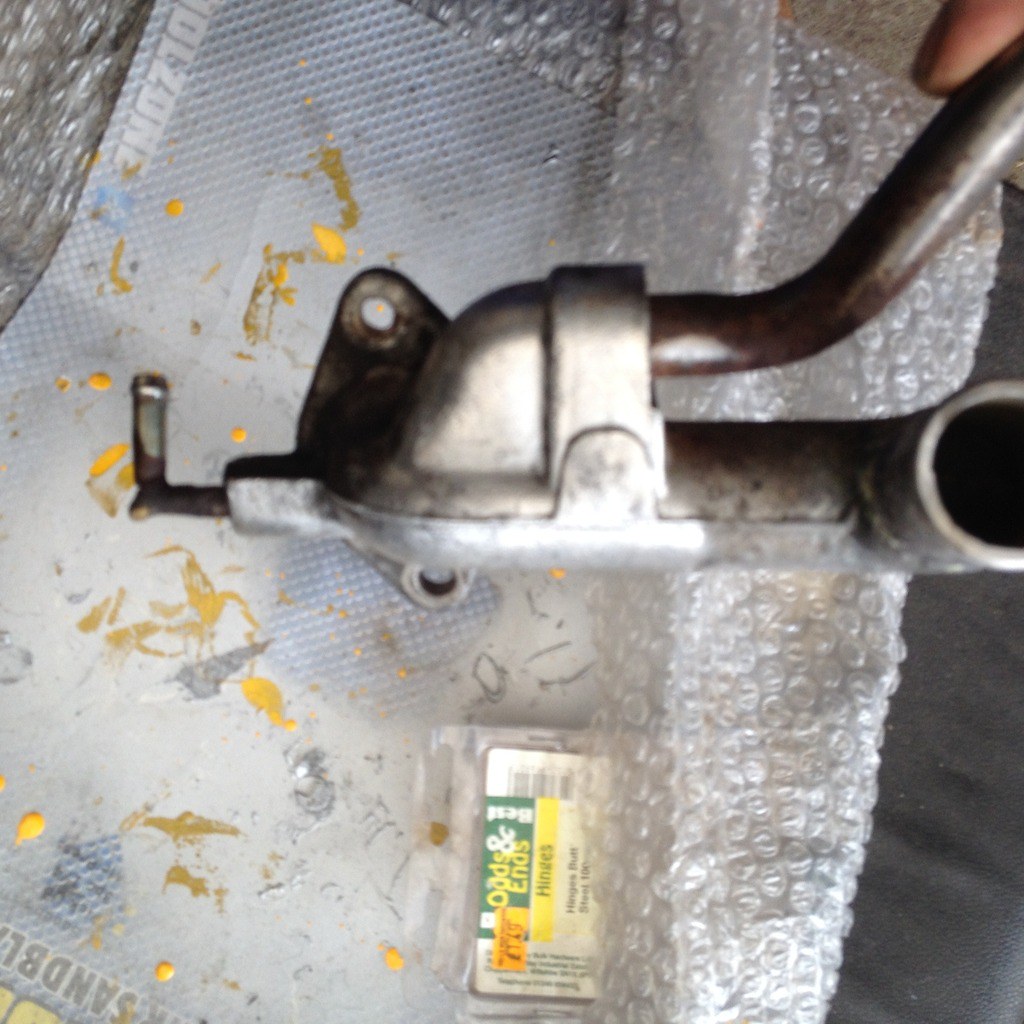
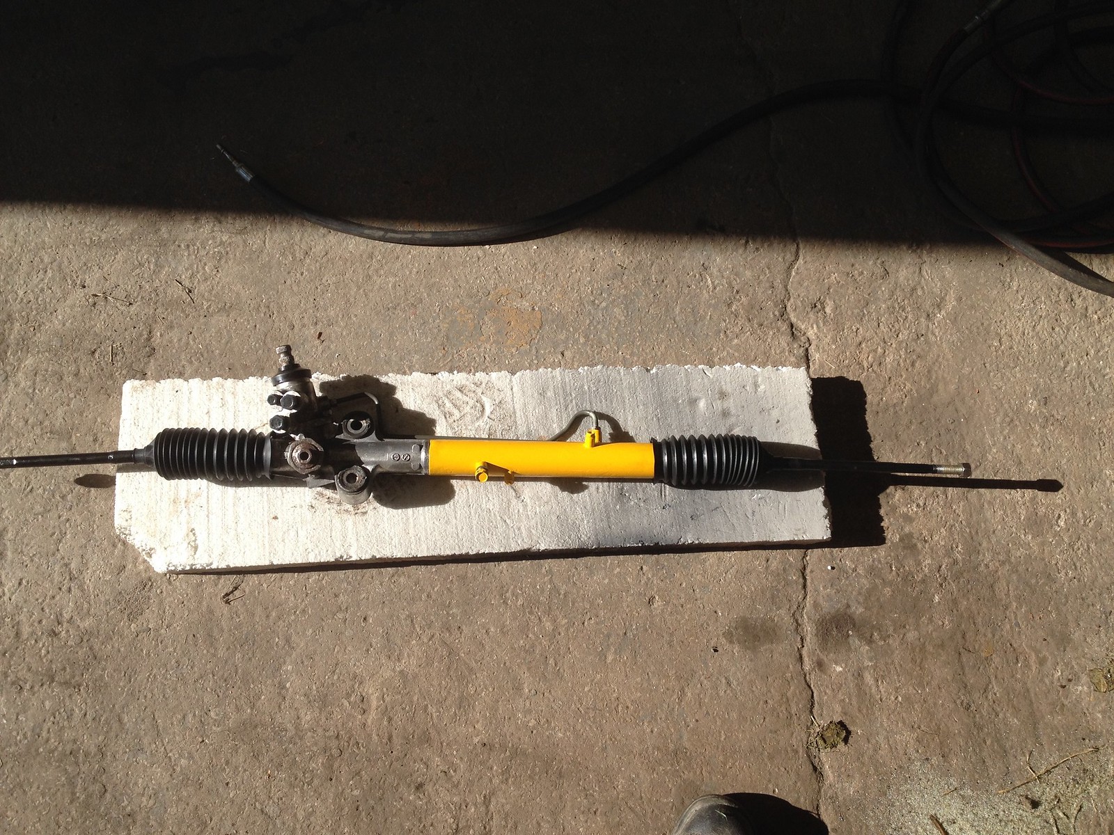
lastmin8264 If going down the simple route in short the answer to your question is yes and I know Stuart has used this approach. I went for the depower option as I didn't want to be working against any fluid in the rack, pinion housing. I did post details on another thread but am struggling to find so here you go, Stripped from car and on the bench. ![]() 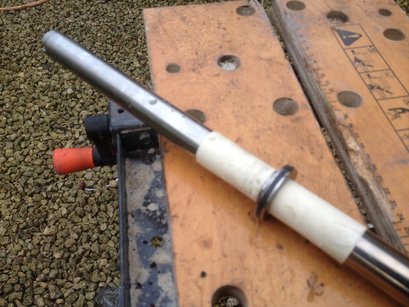 Main parts completely stripped. 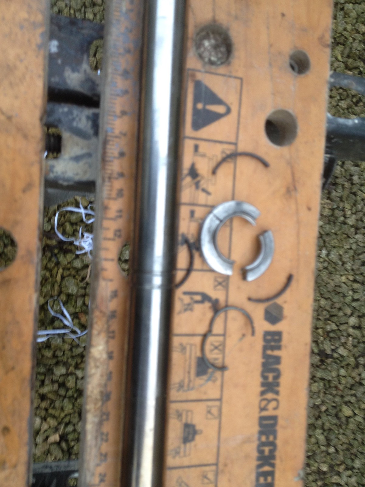 Nothing removed from pinion or housing other than blocking up pipe inlets (I simply used the original fittings with pipes removed and filled the bolts with moly metal - assume this will be fine as no pressure in system - you can buy a bolt kit from USA but its expensive). The piston in the picture above (doesn't look much like a piston more like a fixed washer with rubber outer seal) needs to be cut off. Ive put loads of masking around shaft to try and avoid any damage whilst cutting off using a dremmell. Despite taking care i did slightly mark shaft but nothing to worry about. In putting rack back together I used new locking washers (available but not in MX5parts catalogue you have to ask) between rack and tie rods at inner ends. Also liberally greased, with general purpose grease, all internals before reconstruction. After a lot of thought I also decided to keep the pipe from the pinion shaft housing to the rack (my thinking behind this was to provide some release should any pressure build up in the pinion housing - this may be total overkill but I feel a little happier with it like this). Hope this is what you were looking for. Should add once its stripped down everything is really straightforward. If you need any more info or pictures just ask. |
|
|
|
Post by john on Sept 24, 2015 20:02:46 GMT
Yes thanks very much, could I now also check what's needed to remove abs ?
More than just a new cylinder I guess, I'll make up new brake lines but without abs I can just route direct to caliper, does it need anything else to compensate for balance front/rear? A bias adjuster?
|
|
|
|
Post by mawdo81 on Sept 24, 2015 20:23:52 GMT
Bias adjuster will fail IVA. In the sonic/rocket we use a twin cylinder with balance bar, but the Exocet guys might be able to be more mx5 specific...
|
|
|
|
Post by R2S on Sept 24, 2015 20:25:43 GMT
Yes thanks very much, could I now also check what's needed to remove abs ? More than just a new cylinder I guess, I'll make up new brake lines but without abs I can just route direct to caliper, does it need anything else to compensate for balance front/rear? A bias adjuster? You need the non abs servo (which has the valve), I got a second hand one from Weshy1 (on the forum) send him a PM i'm sure he'll be able to help. The unit he sent me was in really good condition just needed a bit of paint. |
|
|
|
Post by R2S on Oct 9, 2015 14:13:49 GMT
 Not the clearest of pictures but you can just about make out the pipe I retained from the rack to the box. 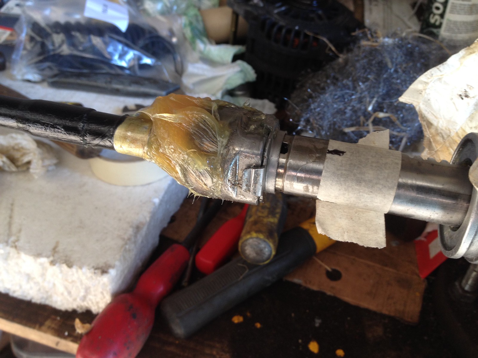 And heres one showing the retaining/locking washers available from MX5 Parts |
|
|
|
Post by R2S on Oct 20, 2015 17:12:07 GMT
Been a while, months in fact, since Ive been to the workshop but called in today and thought it worth posting a photo of the shocks and the pieces used when retaining the MX5 top mounts (i couldn't find one anywhere, all the vids on youtube show how to take the originals off, in great detail, and then the new shocks appear in the vids built up!). 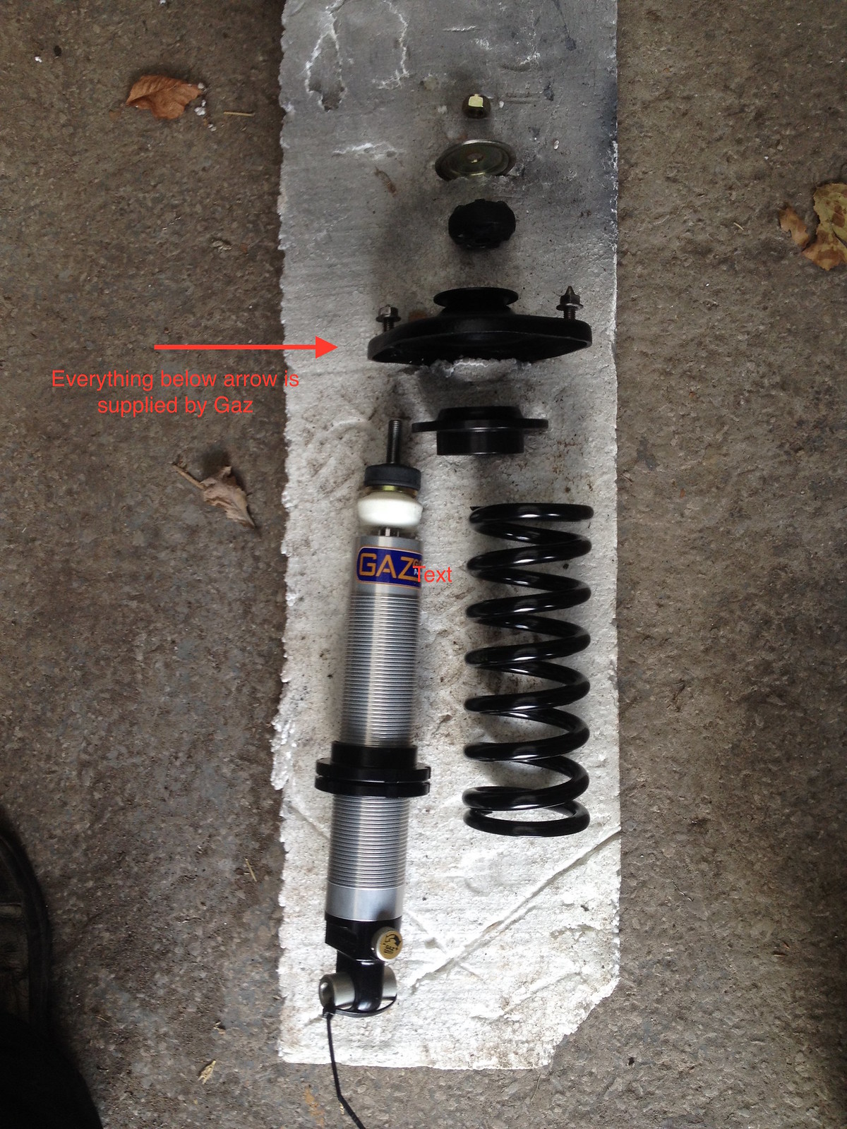 Basically you take everything supplied by Gaz and remove the very top washer. All the bits below the arrow are then put together under the top mount. I'm sure I have it right but the spring top retainer and top mount appear to be a simple metal to metal finish (PLEASE SHOUT IF I HAVE THIS WRONG). 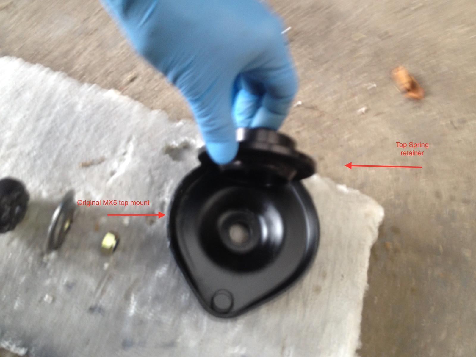 Apologies for focus but a was struggling to hold everything and take photo. 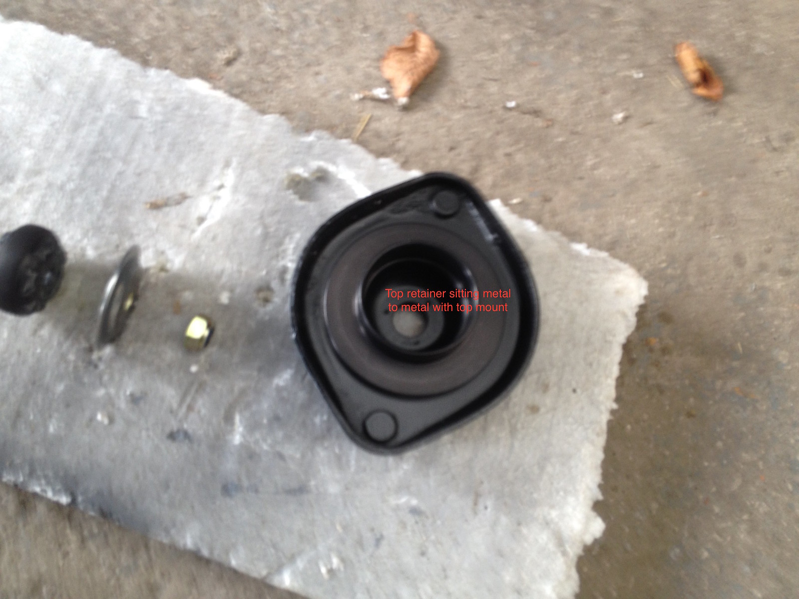 Thought I'd include a couple of shots or the rebuilt rear subframe/axle too.  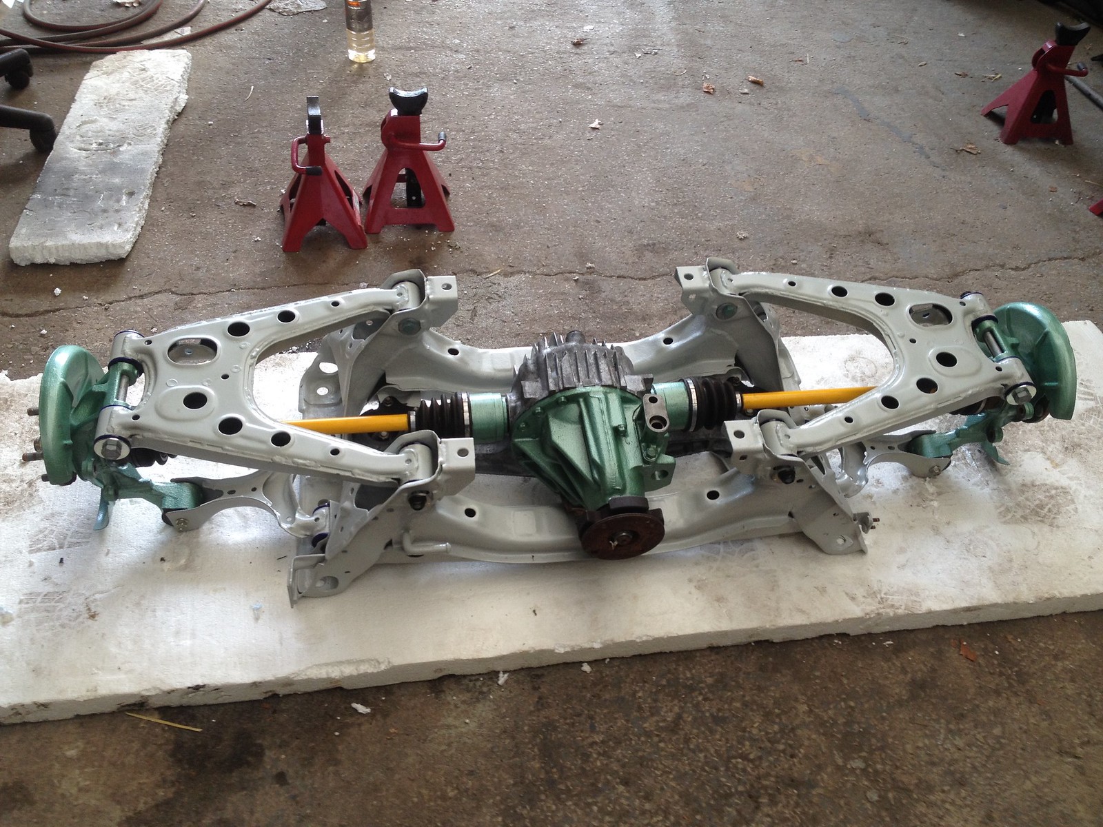 |
|
|
|
Post by R2S on Nov 14, 2015 17:46:43 GMT
So long since I took the from end apart, and markings removed by powder coating, I dont know which side front upper arms fit. Whilst I know the arms themselves are symmetrical they have the a captive nut (indicated in photo) making them handed. Cant tell from workshop manual so hoping someone can tell me does the nut go to front or rear? 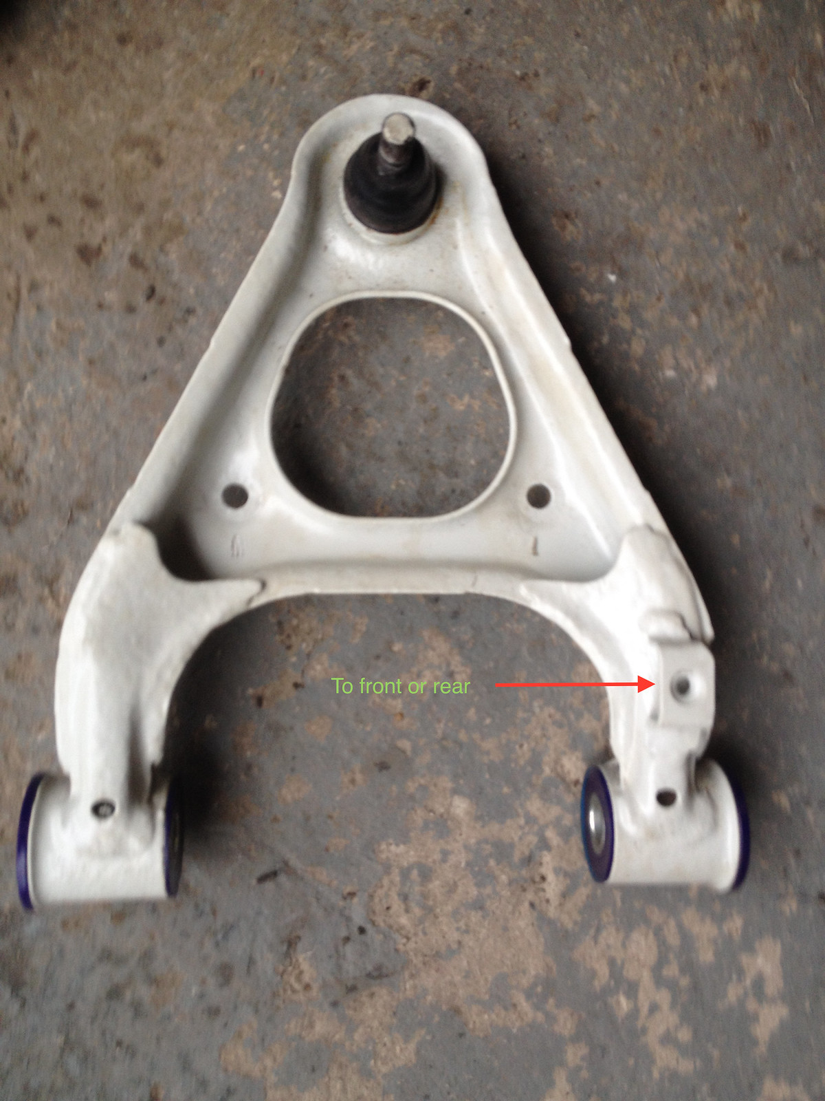 |
|
|
|
Post by gwnwar on Nov 14, 2015 19:54:20 GMT
It goes to the front for ABS harness/cable to secure.
|
|