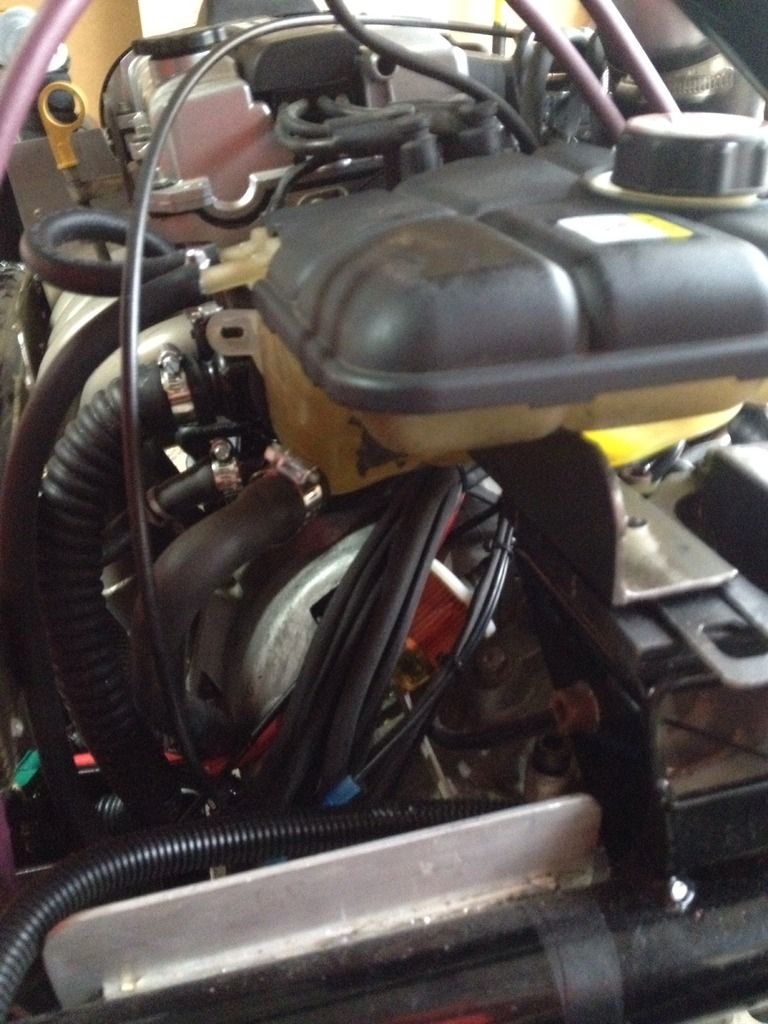
Coolant Tank mounted! I used a small plastic tank just to get the engine up and running - now had to replace with the proper tank with coolant in it. Not very smart on my part.
Spent quite a bit of time seeing how it would fit, so when the engine cover is mounted, the coolant tank fits.
Finally decided on a bracket bolted to the engine mount with and then the tank epoxied to that. Made up the bracket and epoxied it to the tank last weekend. the biggest PITA was getting the pipe fitted back onto the tank. A bit of dish soap did the trick after banging up my thumb (twice!) trying to slide it on. The real pain was switching out the pipe as per the standard coolant flow - as the system is full of coolant!. Bit tricky and a small spill, but got it done.
Bit rough and no paint on the bracket yet, but for now, it will work.
Merry Christmas and Happy New Year (in advance) to all!.
Took the family to Starwars last night. Respectful of the original ideas. nice.
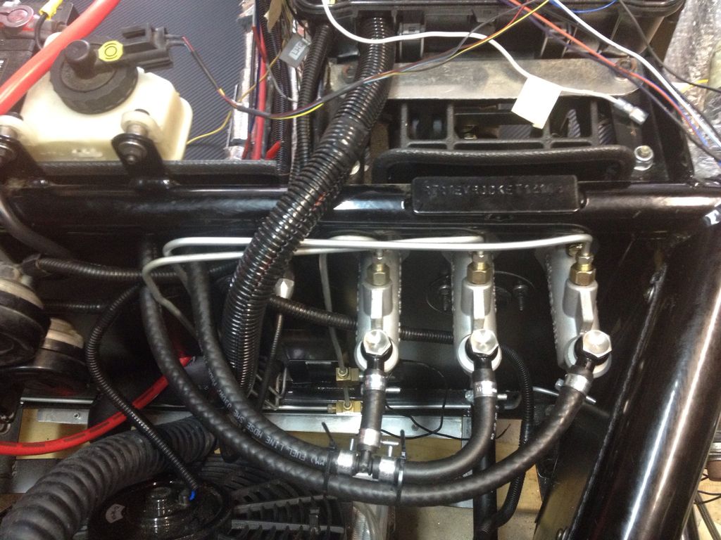
Next get the brake and clutch master cylinders installed.
First, I got three different sizes, .625, .700 and .725.
So I figured .625 for the clutch - just one slave cylinder to drive and a small one at that.
.700 for the Rear brakes and the .725 for the Wilwood calipers and Slotted brakes disks on the front.
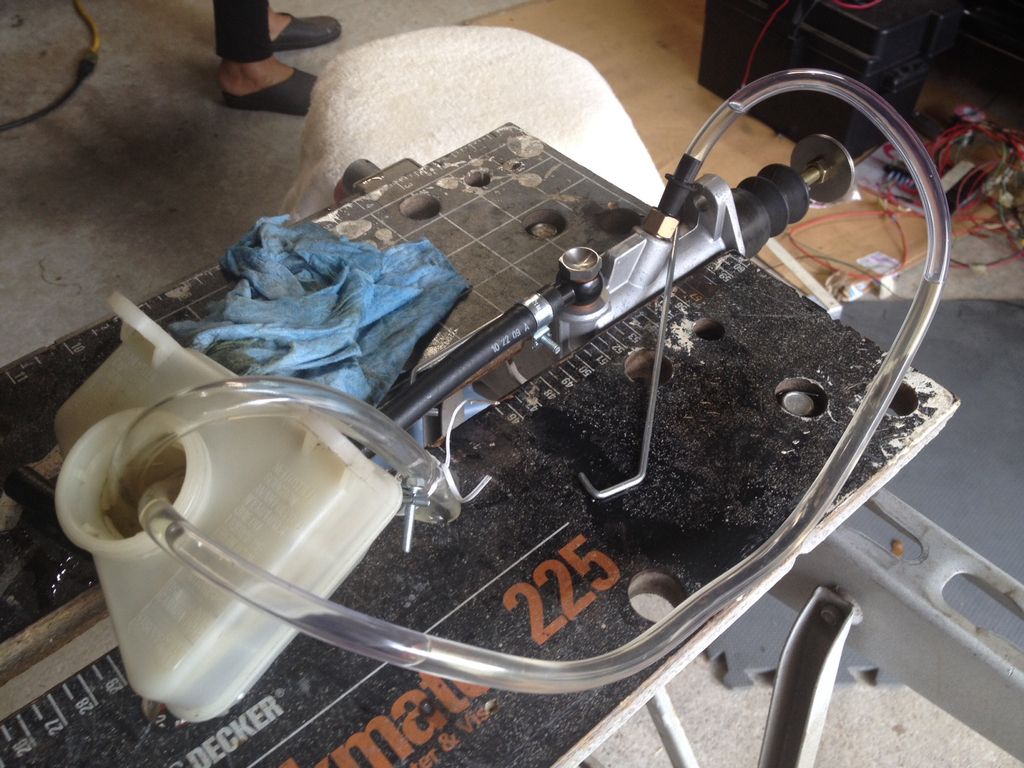
Did some reading and decided to bench bleed the new master cylinders first to get all the air out from the one way valve inside the body.
Cleaned out the donor tank as best I could - it was quite grungy. This is the set up Bled them one by one and then installed - it was a bit messy, but ended up with this.
Next is to get the pedals connected up and set the balance bar. Will start with a 50/50 setting and go from there. it looks like Texas does not require a drilled and locked balance bar at this point.
By the way, if you have not bench bled cylinders before, it is well worth the effort - a quick 'tube search will give lots of good solid examples on how to bench bleed a master cylinder.
Today 31 Dec, 2015 was a pretty special day - first day on the road - well, at least up and down the driveway and around the circle at the end of my street!
Dr Brian gave up his afternoon to come over and help out cleaning up the tunnel area, making sure it was all ship shape and tidy while I replaced the Brake T and switch. This time, no leaks! - so a quick re-bleed of the Clutch line - no bubbles, and time for a short run up and down the drive way.
Had to fiddle with the gear shift cables - it would not quite go into reverse - just made a small adjustment (about 10mm or 1/2" on either end) making the cable a bit longer, and it goes into reverse perfectly.
Still got lots to do - the wiring is still messy, Brakes are spongy and I am sure there are a few loose nuts and bolts (beside the one behind the wheel!) so that is something for the New Year.
Hello Dave, We got a lot done this weekend and learnt alot. Can you post some pictures of our computer/fuel pump electronics box. Another thing that I think we are proud of! Brian G
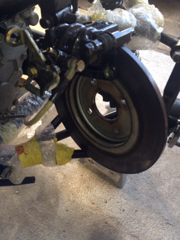
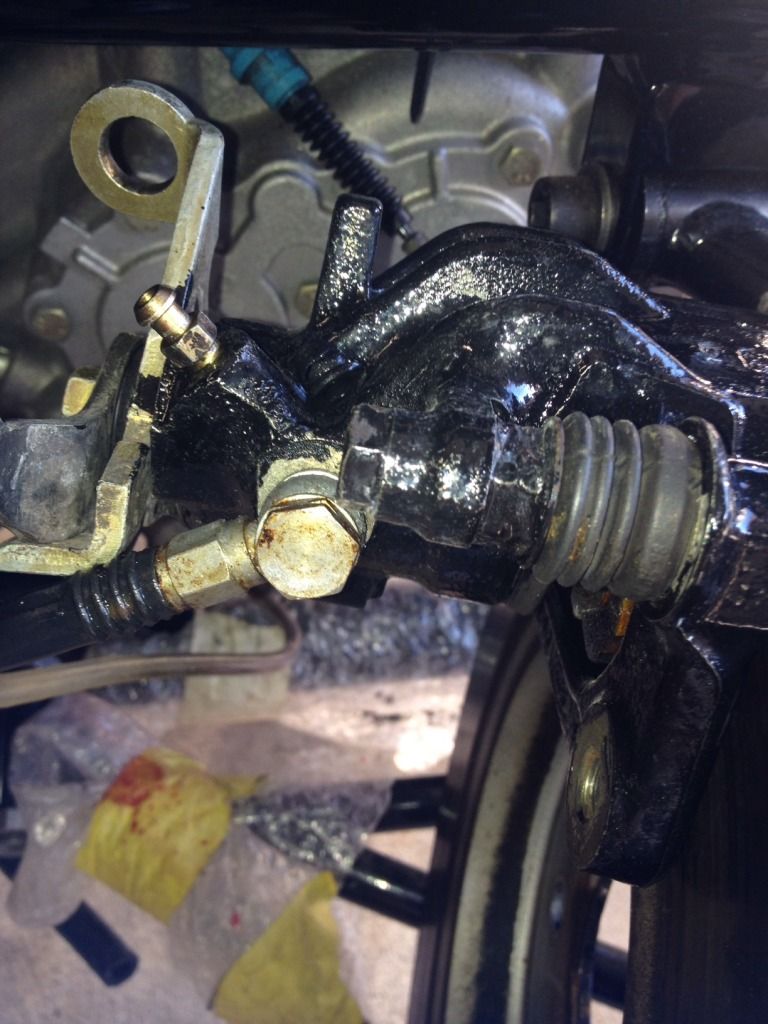
Bleeding the rear brakes - very spongy - after some reading I have to take off the rear caliper/disk and turn it upside down to get the bleed valve above the piston.
the detail of the bleed valve - we see the bleed valve above the cylinder - so the air can escape via the bleeder valve.
Brakes are now pretty solid - set the balance bar to 50/50 as a starting point.
Right Front brake now locks up - so the left front needs to be re-bled I think.
Moving on to cleaning up the ECU wiring. Dr Brian helped me with a little alloy box to hold the Fuses/Relays, ECU and other modules (IMRC - Intake Manifold Relay controller, Fuel Pump Controller) Still need to clean up the wiring and make the wires the right length - but much better than what it was.
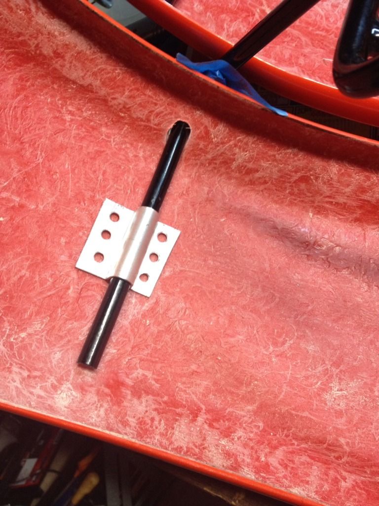
Another small job is affixing the front wings to the wing stays. Made up some little plates to give me a few more square cm/inches of holding power for the PU adhesive. Probably should have rounded the edges - on the other hand it the stress is to pull it off the wing, not push through it.
Ordered and installed a fan controller (40USD or so) as the coolant relay was not working as I thought it should.
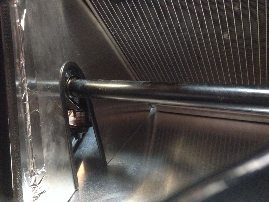
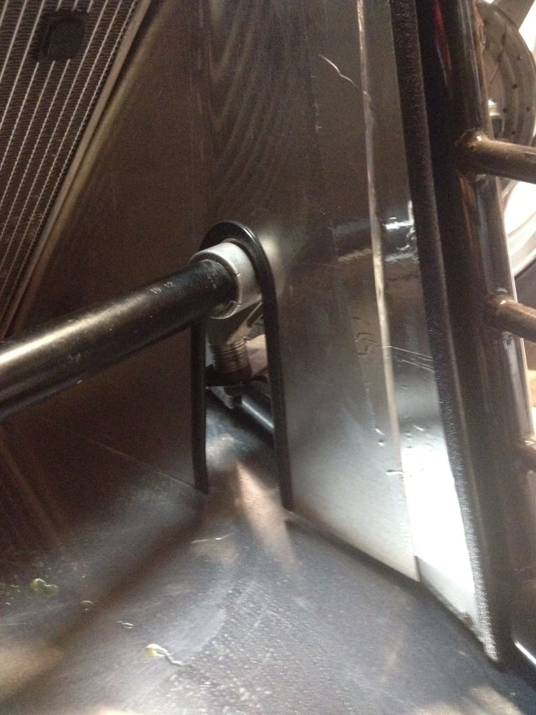
Also installed a radiator shroud, so that all the air coming in the front grill of the Rocket goes straight to the radiator, and not around the sides. This is just temporarily taped in place to see if it works - without it, there is about 6" or 130mm of space on either side of the radiator to the side of the car.
Mr Bernoulli would tell us that the air speed would drop inside the space which is larger than the front grill, and with so much empty space around the sides of the radiator, I figured it was not very efficient with a lot of air going around the radiator, instead of through it!. Another view of the shroud - Some late afternoon driving around the neighborhood and monitoring the OBDI temperatures and other stats, I set the fan to kick in at 175F (~80C) rather than the 195 of the ECU, the overheating I was having has now been solved.
I have added some extra runs of wire (18 gauge) from front to back, as the KOSO Gauge has some sensors on the engine (Temperature, RPM and Driveshaft pickup for the speed sensor) meant I did not have enough wires in the standard harness.
With Dr Brian's help, we got the gauge set up with Speed, Overtemp sensor and other settings. Just have to connect to RPM sensor wire and will have all the sensors on the gauge working.
my ODBI tool of choice is the DashCommander app on an ipad using a PLX Kiwi wifi connector. I am exploring the BlueDriver bluetooth ODBI tool, which is more complete on the diagnostics side (all of the Ford specific PID's are included)
Although DashCommander which has some in-app purchases for some of the Ford specific PID's, has a lot more gauges and user created dashboards you can use or modify.
Moving on to the Hood/Bonnet
I had previously bought and installed some mirrors with built in indicators, and mounted the small indicator bezels on the very front edge of the hood and then glued all the wiring along the inside edge to keep it tidy.
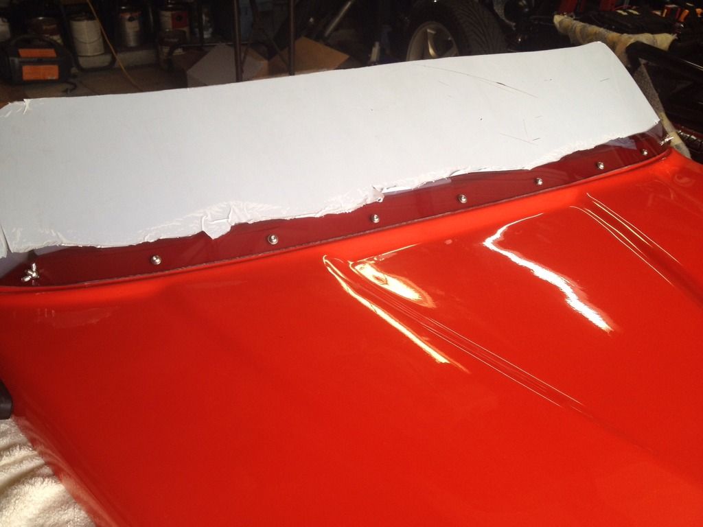
Bit nervous about drilling and installing the windshield. Found the center point of the hood and the windsheild and worked out the spacing to put 9 bolts across the width of the hood. Used Masking tape to mark up and drill out the holes, starting with a single small drill bit and gradually using a larger bit to get to the right size. I mounted the middle bolt and then carefully aligned all the other holes on the hood with those already drilled in the windshield, and worked my way out from the center to ensure everything lined up.
A sharp eyed reader may see a wingnut on the end bolt - and mounted with the wingnut on the outside. I did this to make it easy to tighten it down, and used a hair dryer (thanks to my wife Amparo) to head the windshield as I bent the corners and tightened down the wingnut. It was not a cold day outside, but I thought anything I could do to de-stress the lexan windsheild was a good thing.
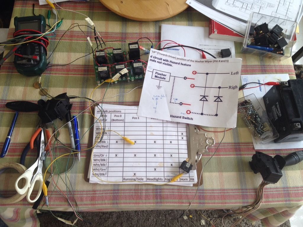
Back to Posting, not really sure why I stepped away. Here we are and back to it. I have been working on the Rocket, and doing some up and down the street driving to make sure it is all working. and been ignoring the lights and other required bits and pieces. A while back looked at all the switches on the steering column. The Wipers/washer stalk looks like it has enough switching functions to let me do most of what we want with the lights (side light, Main Beam, Fog, and even Horn and Hazard switch. This may not pass muster with the authorities, we will see what happens. So after spending several months of a couple of hours per weekend working on this in the car, in a garage approaching 35C or 100+F temperatures, my friend Dr Brian said simply he built his switch harness on the kitchen table in the nice air conditioned house. After looking at the switch units, indeed, they pop out very simply with a little clip!!. Undid all the under the steering wheel wiring and bought it all inside, along with a relay panel and the manual. After a few hours of fiddling around and look at the manual, I drew up a little logic diagram of the switch logic on the Wiper/washer stalk, and then put it all together in a couple of hours. Will post that logic diagram in the next few days. I used a buzzer to test each of the relay output as I moved the switches into the different positions, and everything seems to work as planned. We have two diodes on the Hazard switch, so we don't back feed the normal indicator positions, although had to put another relay to make one of the switch positions drive the hazard switch. The Indicator and High Beam/Flash stalk (on the left in the US at least) is completely standard. Will need to put the little icons on the wiper/washer stalk so I know what everything is! First Position is off Second Position is Side lights Third Position is Main Lights. Forth Position (top) is Hazard (via a relay) Washer is horn (although I might go back to the horn button on the steering wheel)
Finally got back to the wiring, after working it all out on the kitchen table.
We have horn, lights (Side, Low and High beam) , Hazards, indicators all working off the two stalks on the Focus steering column. Not sure if they will pass muster with the authorities when we get an inspection, but they are all working from a small bank of relays in a plastic waterproof box mounted on top of the steering column just under the hood (bonnet).
Will mark up the stalks with new functions using the standard icons for everything.
Should wrap it up tomorrow morning.
needed a couple of diodes and a relay to get the hazard lights working - diagram should be drawn and posted here tomorrow morning.
I have a fan relay driven by a temperature sensor mounted on the radiator, and it has the facility for a small override switch - will install that so if the temperature stays high I can override the fan in our hot South Texas summers.
Feel pretty pleased when the lights, indicators and everything works as planned! Now I can drive it around the neighborhood at night without scaring the local cats and dogs.
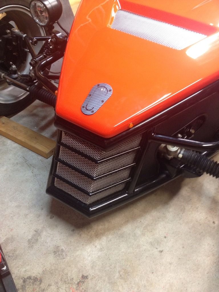
Spent some time this weekend on the grill and hood (Bonnet) it was a bit scary drilling into that bright orange hood, as they say, measure twice and cut once. measured from the front inside lip of the hood and then centered on the hood, and drilled a 1/8" hole, and it was spot on top of the Aerocatch pin. They come in a bag with two latches, one for the back and one for the front. Although it is plastic, it is pretty well made, and they have a nice template. I chose the fake carbonfiber design, to match the floor pan.
The grill matches the hood and engine cover grills - found some at the local bigbox hardware store - Hurricane screen for windows. can be cut with scissors. We will see how it stands up.
I am not happy with the hinges I chose, the hood sits too high - something to work on next weekend.
The indicators are blinking too fast, I have a bit of a mix of LED and normal bulbs, so I suspect that is the reason - local parts store had an electronic blinker - will see how it works.