|
|
Post by casesensitive on Apr 6, 2017 8:32:32 GMT
ARghh, just as I was finished the post, browser killed it on me.. Take 2; It's been 3 weeks since I finished wiring up my ME221, but I haven't had a start since I pulled out the Ford ECU. I've all but eliminated my 'standard' issues, so I'm left with the unlikely. FuelVirtually certain is ok. I can hear the return line gushing into the tank. I put a test tube over the pressure monitoring schrader valve and gave it a skoosh while it was priming, definitely got pressure at the intake end of the rail. Then I pulled the injectors out of the manifold, attached a test tube to each one, and with the spark plugs far away in their test rig, cranked the engine over for 30 seconds or so, presto, each tube had about the same amount of fuel in it. 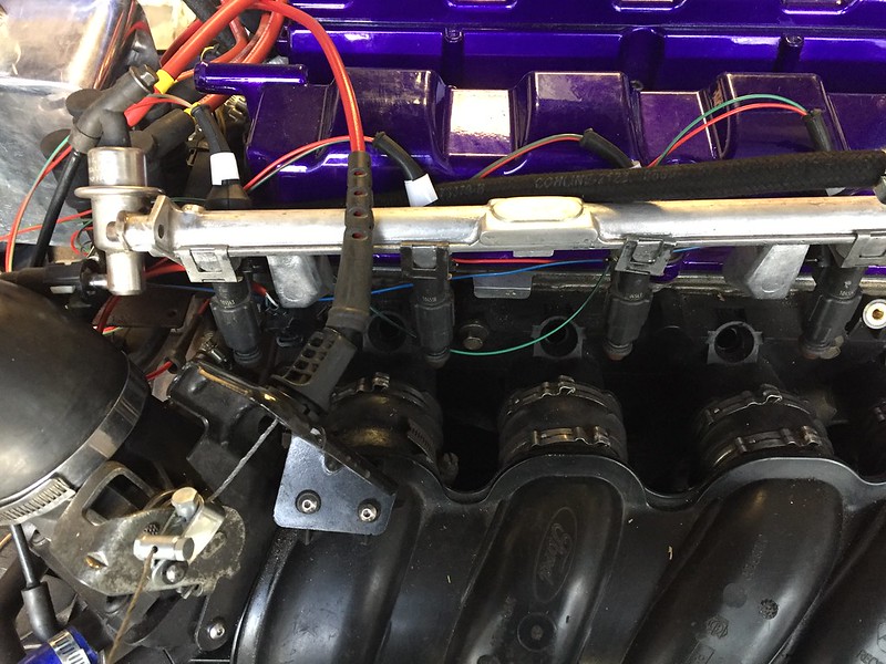 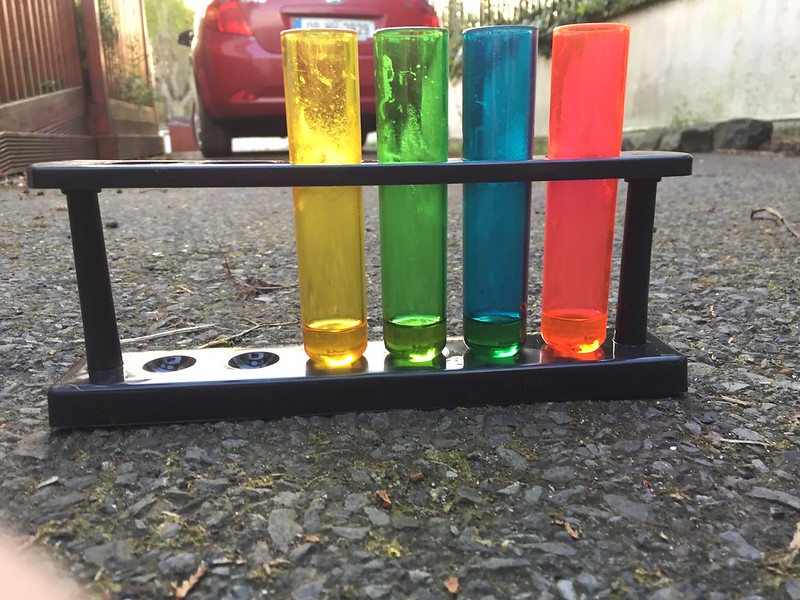
AirHard to know to be honest. Engine seemed like it wasn't getting what it needed for combustion, so I assumed the idle wasn't opening, so I moved the throttle to 5-10% open to get some air in. This of course invites more fuel in too, so it'll flood faster. Occasional spurts of black smoke from the exhaust suggest that some air/fuel is getting expelled, if not properly burned. Also, see compression below, there is a sharp blast of air out of the compression tester leads on the upstroke, so there's definitely some air getting in. This was without partial throttle, so the idle must be letting in air.
SparkAgain, reasonably certain I'm getting a spark, but not necessarily at the right time/point in the stroke. In addition to confirming I have spark with 4 spark testers used simultaneously, I have pulled the plugs out, put them into a 120* folded bit of scrap with 14mm holes tapped into it, and earthed to the chassis. All 4 sparking away happily. All the same, the plugs did look a little sooty despite the attention with the 400 grit and meths, and their spark gaps weren't even (though I set them all to 0.7mm), so I replaced all 4 with Ford OEM copper plugs with a 1.3mm gap. Put them into my test rig, and the sparks looked identical. 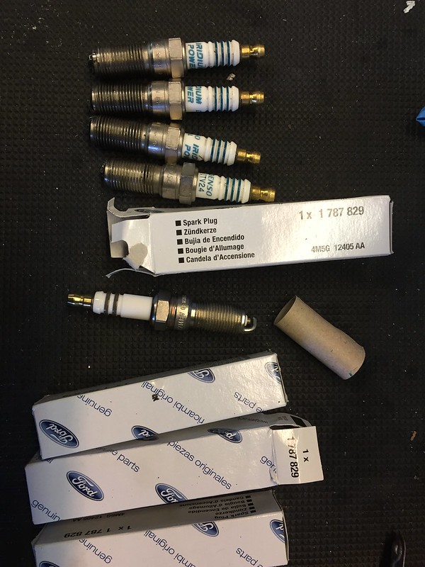 Slowing the video down to .25 speed shows that 1 and 4 spark together, and 2 and 3 at about an even interval. Nothing to see here really. TimingSeems that (my?) Blacktop/ST170 engine doesn't have any timing marks on the crank pulley, and had some pretty vague (<1mm) mark on the block, with no idicators of what they might be. 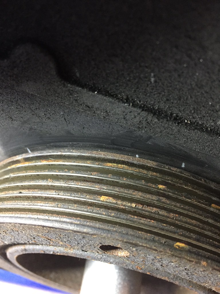 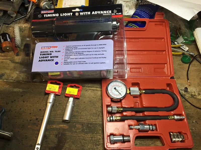 Going to establish TDC properly with A Long Thing in cylinder 1, and mark out TDC on the block and crank pulley. Plan is then to use naught fancier than a protractor to figure out 10/20/30* BTDC for my spark timing marks (MEITE software opts for ~17* BTDC to spark as a default as cranking RPM, more as RPM goes up, obvs). 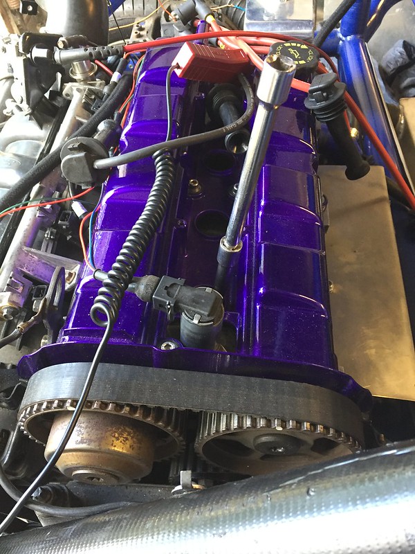 Compression CompressionYears ago I had a Puma that developed mayonaisse oil after a particularly spirited run, so I bought a cheap compression tester. I was frustrated because I never got it to display anything at all, I now I know why. After going through considerable difficulty threading the various adaptors into the very deep plug sockets (a known Zetec issue), and attaching it all up with PFTE tape between each connection, the gauge showed 0psi. Turns out the gauge was probably busted the whole time. So that test was mostly a bust. I was able to test that there was SOME compression by holding my finger over the top of the test leads, and it was pushed off with force. BUT; the engine was pretty healthy 2 months ago, I find it hard to imagine I've created a compression leak in that time. I have bought a new compression tester and a deep reach adaptor to go down into the recessed plug gap. And a cam/crank locking set for good measure. 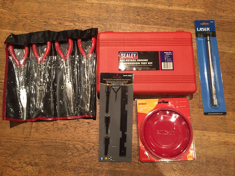 |
|
|
|
Post by casesensitive on Apr 13, 2017 8:46:08 GMT
Fusing stuff sounds like a good idea. Where can I get my hands on Steve's base map? I have just equipped my ST170 engine with GSXR ITB's so that would get me going too. I really need to update my build thread! ME themselves mapped Steve's car, VVT and all, and his .meite map is here, labelled BETA do not use :-) If, like me, you're using the Focus ST170 stock CLT, IAT (from the MAF) and TPS, and didn't mess up your wiring, reversing the CLT and IAT sensor assignments, you'll want my variant of his, which is here. Should be enough to get you moving, though if your setup varies significantly from his/mine, you'll want a proper mapping session to sort it. It's worth examining the curve I observed with the Intake Air Temp sensor component of my MAF; it's a shonky-looking thing, probably because my MAF is 15 years old. Actually, for complicated reasons, it's mawdo81's MAF, but it's still not new. The results I got from a £9 intermotor IAT designed for a BMW were far cleaner, and I'll be swapping that in when I ditch my Ford intake system for the GSXR / DanST / airforceone shiny. |
|
|
|
Post by casesensitive on Apr 17, 2017 20:01:03 GMT
As we’re out of action for a bit, while Motorsport Electronics have my ECU, I decided to sort a few issues with the wiring I’d never be happy with. First thing was to put fuses into lines that carry current back to the ECU by any means. I have space in the fusebox, so why not. 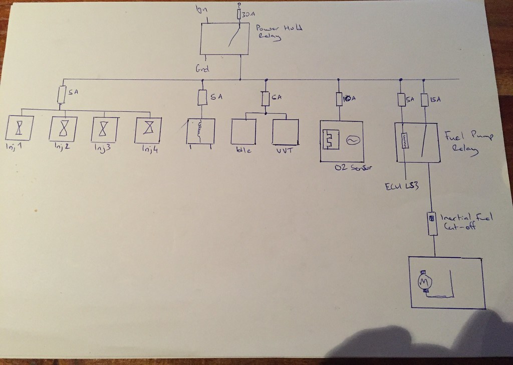 The second part is in part about reducing EFI by twisting pairs of wires around each other, but also a nice way to get clean bundles of wires. Each signal and fused supply line were twisted around each other, then nearby pairs wrapped around each other, then those pairs wrapped into one big bundle, ready to be surrounded in convoluted tubing. 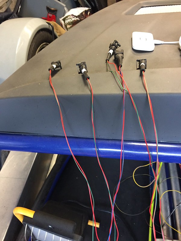 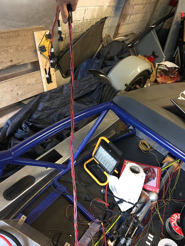 |
|
|
|
Post by casesensitive on Aug 26, 2017 10:48:08 GMT
I'd love to say that the next attempt was perfect, but despite all the measuring, the cylinder 4 hole was out, again. 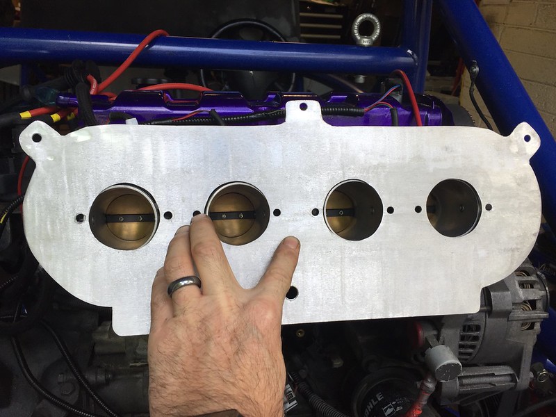 For my 4th attempt, I changed tack at my Dad's urging, and measured all the positions absolutely, rather than relative to its neighbour, so that 1 mistake wouldn't be propagated along. I also made the holes slightly bigger, as there's going to be a slight step between the trumpets and bodies anyway, so I measured the holes to the trumpets and not the bodies. 44mm holesaw 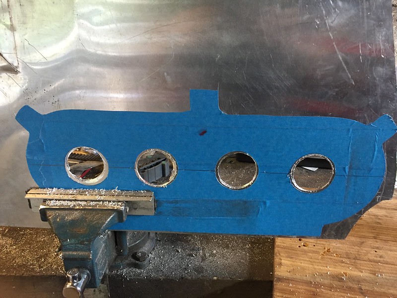 Followed by a LOT of filing, again. Clamped it between flat bars overnight to straighten the bits that I bent with the rasp. 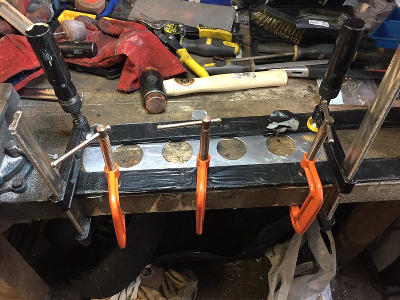 Rough finish, but it fits! 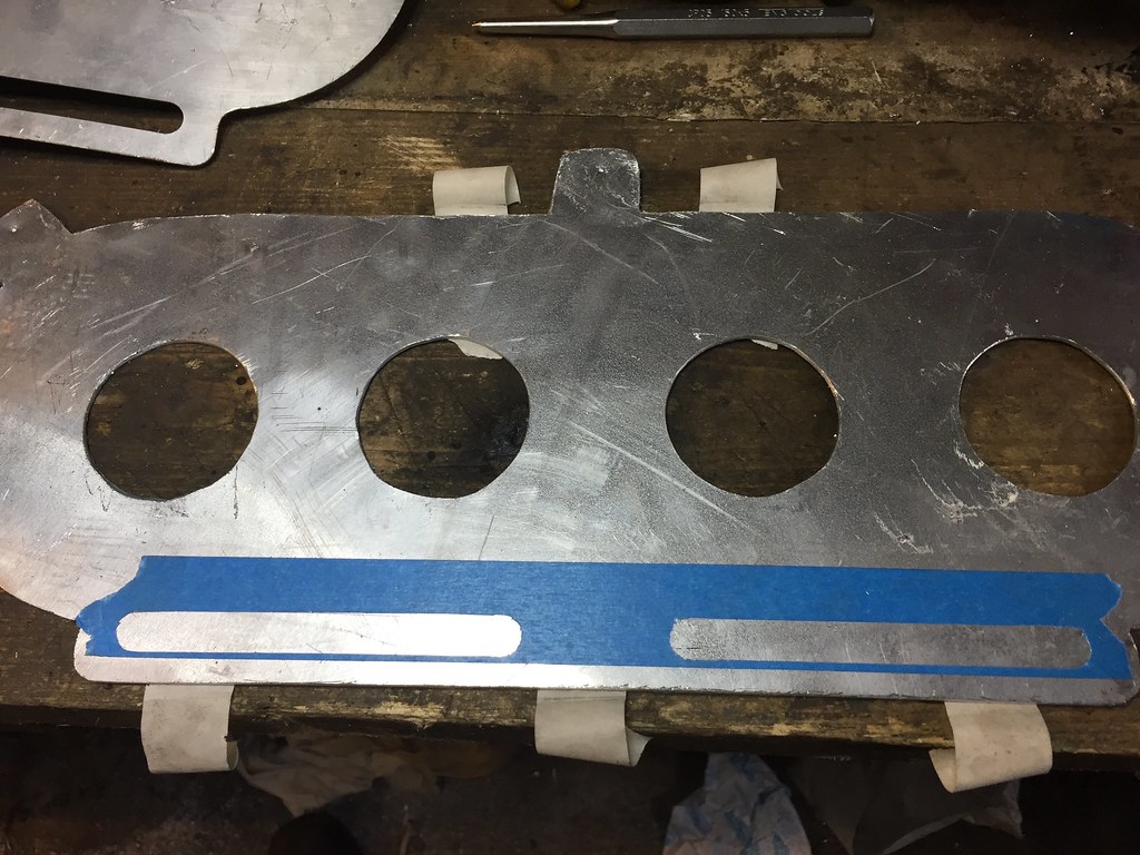 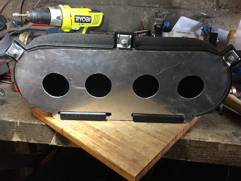 Good lot of finish work, but on the wrong side, engine-facing side got 320/600/1200/2500 grit treatment, trumpet-side got 320 and 600, looks ok though. 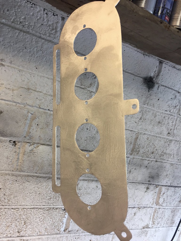 Happy with the result, although, in place, it's clear there's no easy way to centrally-locate the IAT sensor, with wiring connector, they catch on TBs or throttle linkages, it'll have to go to one side or other. All bolts, nuts and washers are now stainless steel. 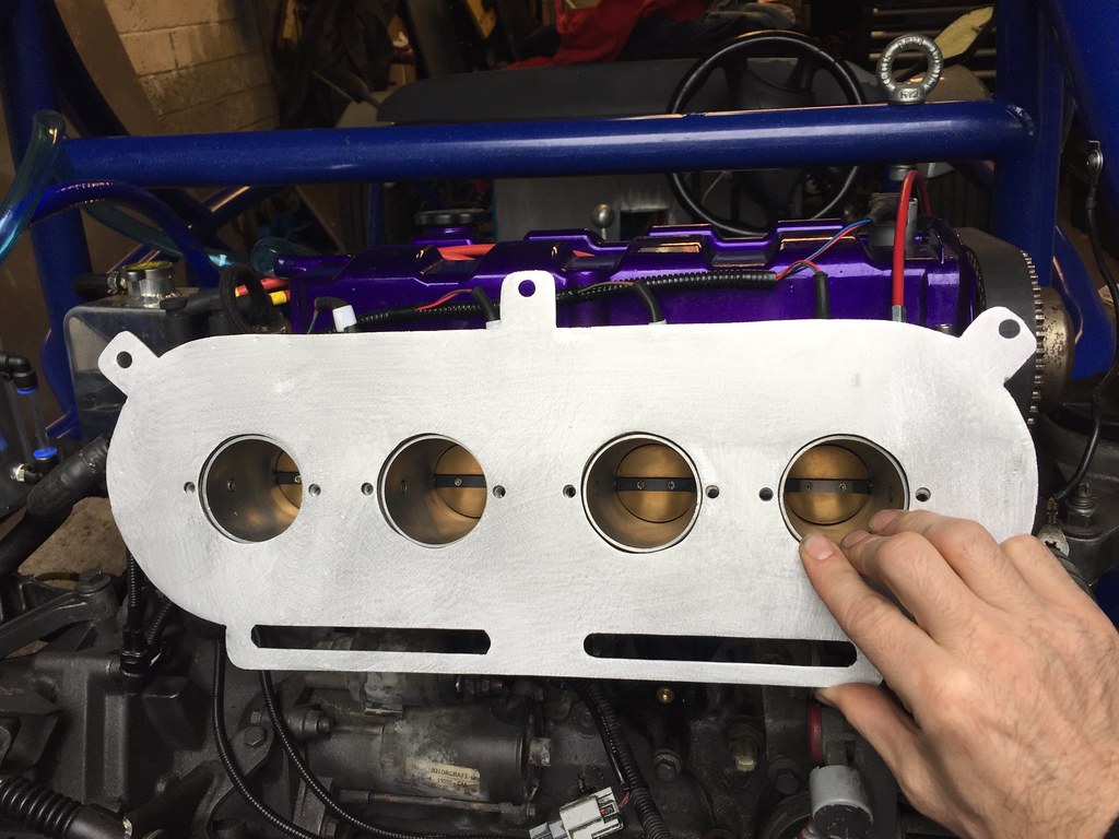 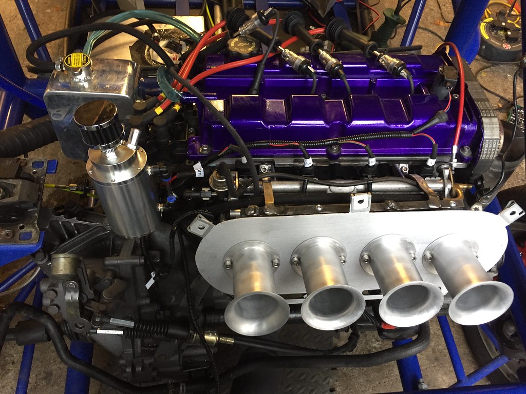 This was dead handy, picked it up at Stoneleigh. 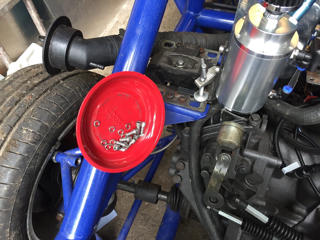 |
|
|
|
Post by casesensitive on Sept 24, 2017 10:05:13 GMT
Front of car wiring this week. I sort of cheated with the relays and fuses, I bought pre-wired relays and a busbar fuse box, great decision; the fuse box isn't wall made, but it saved me a ton of effort. Spyda fuel gauge wizard in the top right to convert ford fuel sender signal to Koso-compatible. It works really well; glad I got it for £30 rather than £44 though, that would have been more painful. 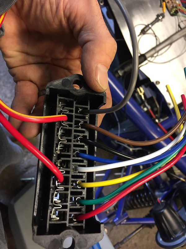 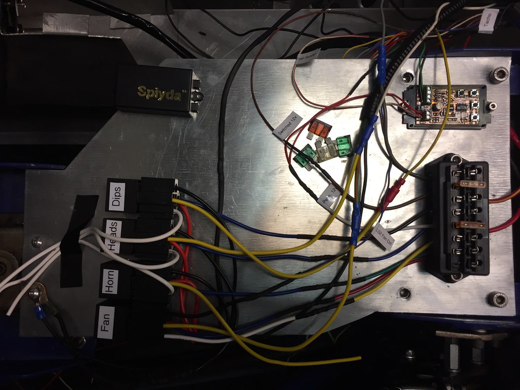 |
|
|
|
Post by casesensitive on Dec 20, 2017 16:16:03 GMT
Yep, stub manifold will fit, though the ports will be off by a touch (ST170 ones are slightly larger). Consensus internet opinion says yes! passionford.com/forum/ford-focus-rs/160501-will-a-st170-inlet-manifold-fit-2-0l-zetec.htmlwww.turbosport.co.uk/showthread.php?t=99564It's all very homemade, as you'll see from my build, but it does go vroom very nicely. Trying to figure out what's included, definitely these anyway: - GSXR1000 42mm ITBs with injector holes bunged up with JB weld (removable)
I went down the route of bending the interlink tabs rather than welding tabs to them, may need to tweak for your own fitting. - GSXR Throttle Position sensor and wiring connector
- ST170 stub manifold, ported to match bodies
- DanST fitting kit (silicone joiners, 8 clips, threaded bar, and some spacer bar that I didn't bother cutting up to use)
- Legit DanST pipercross backplate, that I found unsuitable due to inter-body spacing!
- Pretty reasonable copy of this made from 1.5mm aluminium that works much better.
- Both have an M12 drillhole where my Air Temp Sensor goes
- And a primitive 3mmx12mm bar contraption of my own devising to hold it all in place, including little pads to hold the bungs into the injector holes, in case of misfire, picture below.
- All the spare Gixer bits and bobs, if ya want them, sitting in a box in my garage
I do have short (30mm maybe?) red trumpets that came with the Jenveys that I might part with. Excludes: the 90mm trumpets, filter, fuel rail (I use the standard 2.0 one anyway!), fuel pressure reg (also from 2.0), wiring, injectors, screws and the 3 clips that hold the filter onto the backplate. I haven't balanced them properly; my neighbour at the garage is extremely noise-sensitive, so I can't run the car for long enough to fiddle with the adjusters to get it perfect. DanST backplate shown here Click for monster zoom 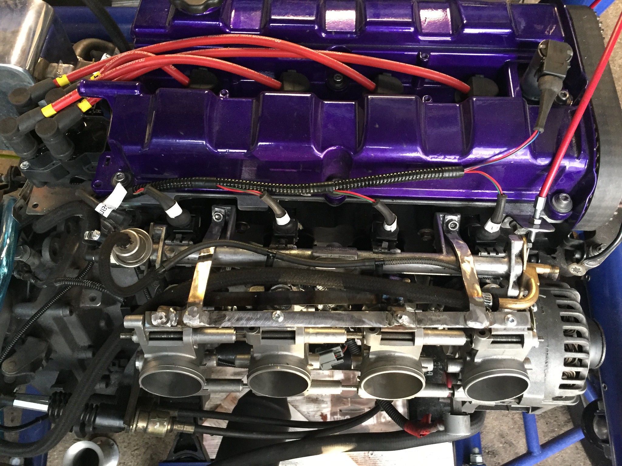 Ported inlet 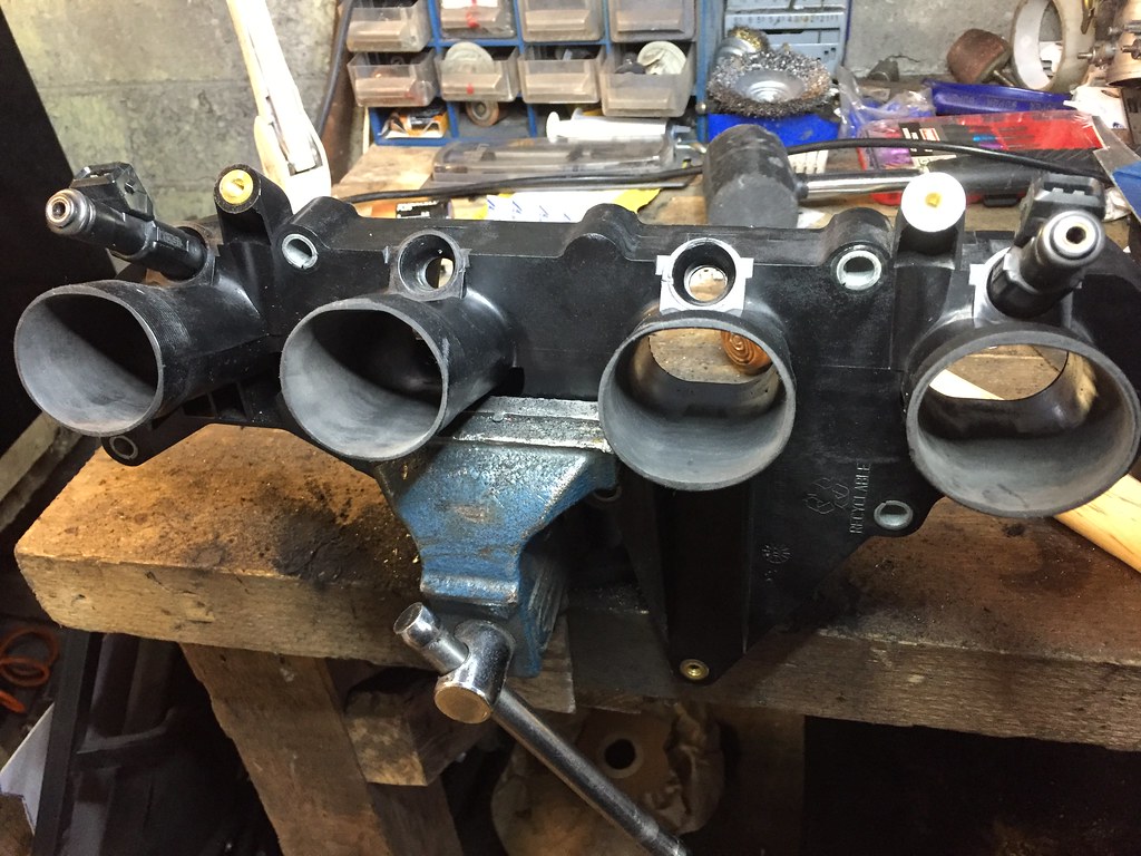 |
|
|
|
Post by casesensitive on Feb 14, 2018 20:08:41 GMT
Bung up the vacuum linesDan ST put 5 vacuum ports in my manifold, which was not only more than I wanted, but 1 more than they provide (very pretty SS) bungs for. Promised 5th one never appeared either. On a roll from my alley welding antics, I turned the TIG torch on the put-fit barbed fitting they supplied with it, a bit of silicon bronze rod and I have what looked like a hollow point slug taken out of a wall. It's airtight though. 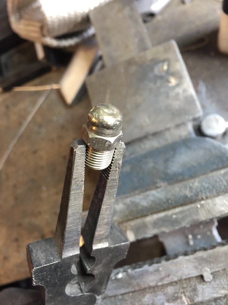 TPS TPSThat slotted in underneath the new TPS wiring; this is now my 4th wiring of a TPS, getting to be a dab hand now. Heat shrink was shrunk once I'd calibrated the TPS with my pedal and in MEITE software. 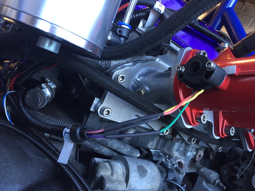 Fuel rail and throttle bracket I spent a long time troubleshooting why my throttle cable wouldn't auto-retract, in the end, I pulled the whole inner out, 1 strand had broken and was catching, so I unwound it. Slotted back in, and then set up a contraption for adjusting it. I welded any bits of bar that I had mounted with bolts for neatness, and filled in a few drilled holes as much because it was a rewarding job to do than it needed to be done. Then needed 5 new layers of primer, paint and clear coat. 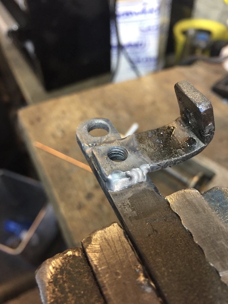 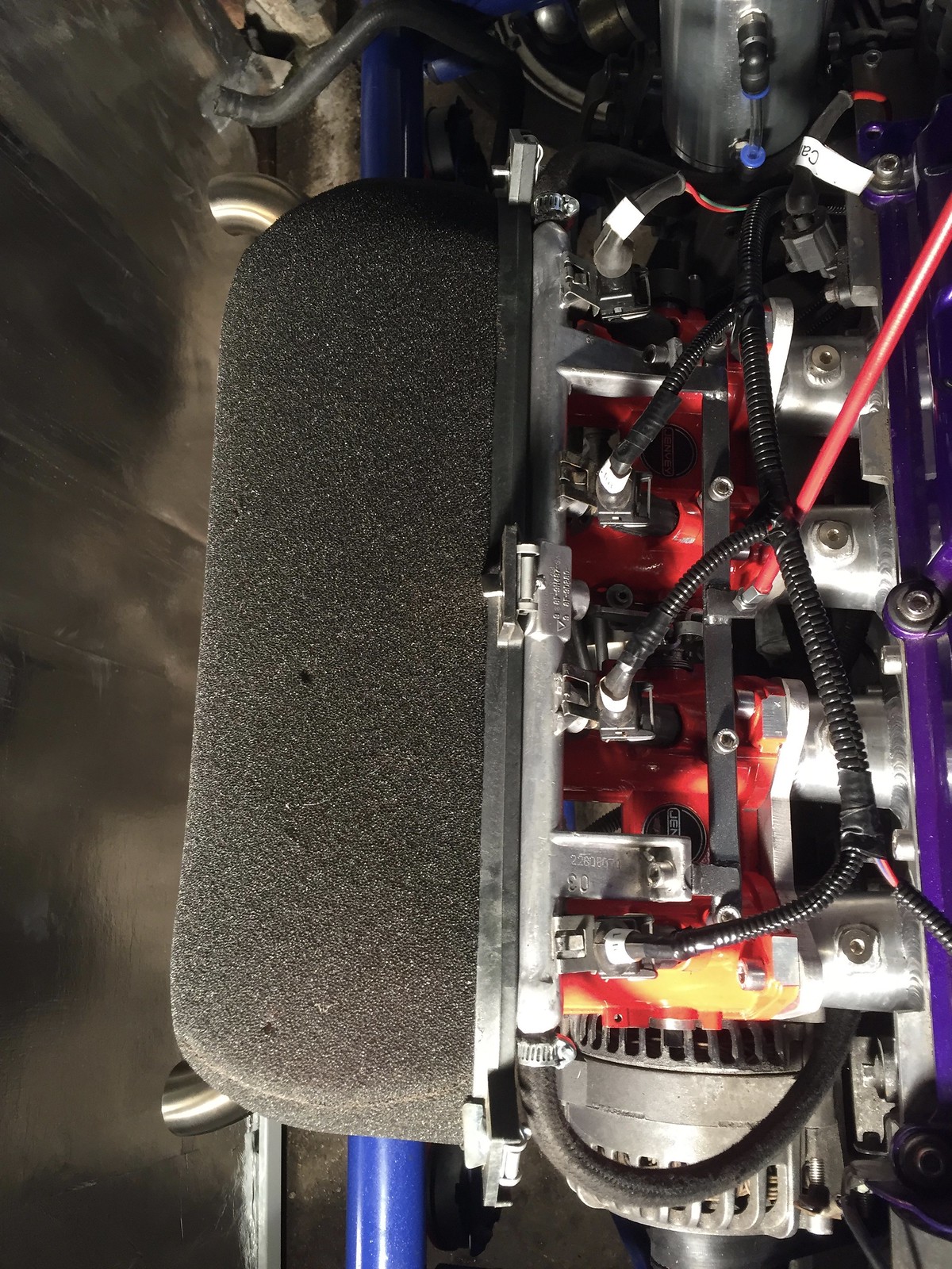 Finally, I found a spot for my Intake Air Temp sensor 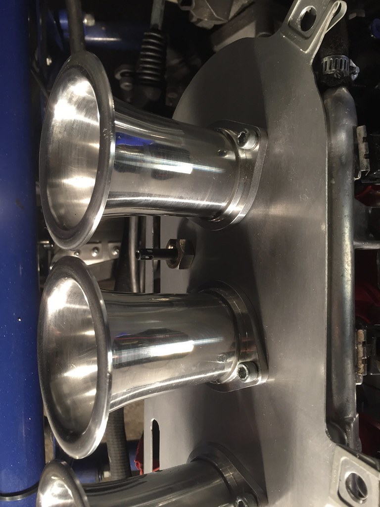
|
|
|
|
Post by casesensitive on Jul 8, 2018 22:23:51 GMT
Went backwards at a speedy rate today, lots of jobs done. Disconnect wiring
make temp gearbox mount, suspend engine
remove driveshafts
disconnect clutch line
disconnect accelerator cable
disconnect torque mountRemove exhaust eh... temporary engine mount, old timing belt as a damper either side to protect the powder coat. 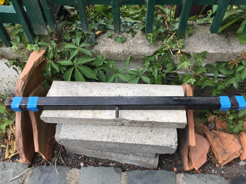 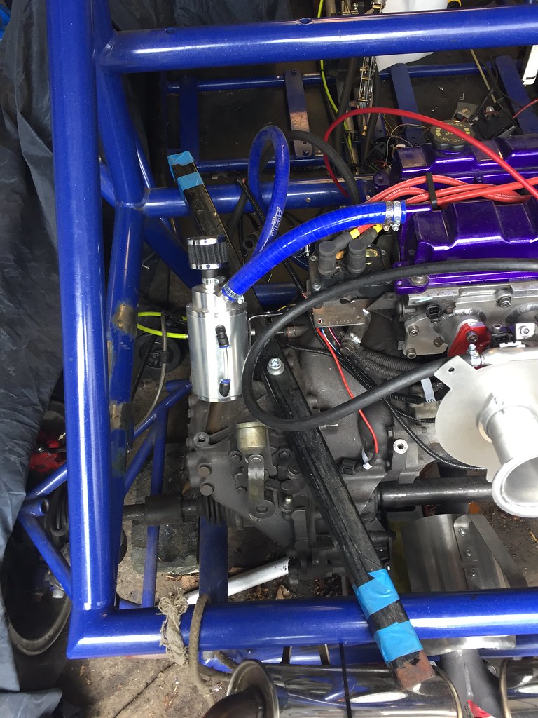 Eejits made my exhaust system in a single piece, making it impossible to take out. Plus the fancy branded backboxes face towards the car. Great. 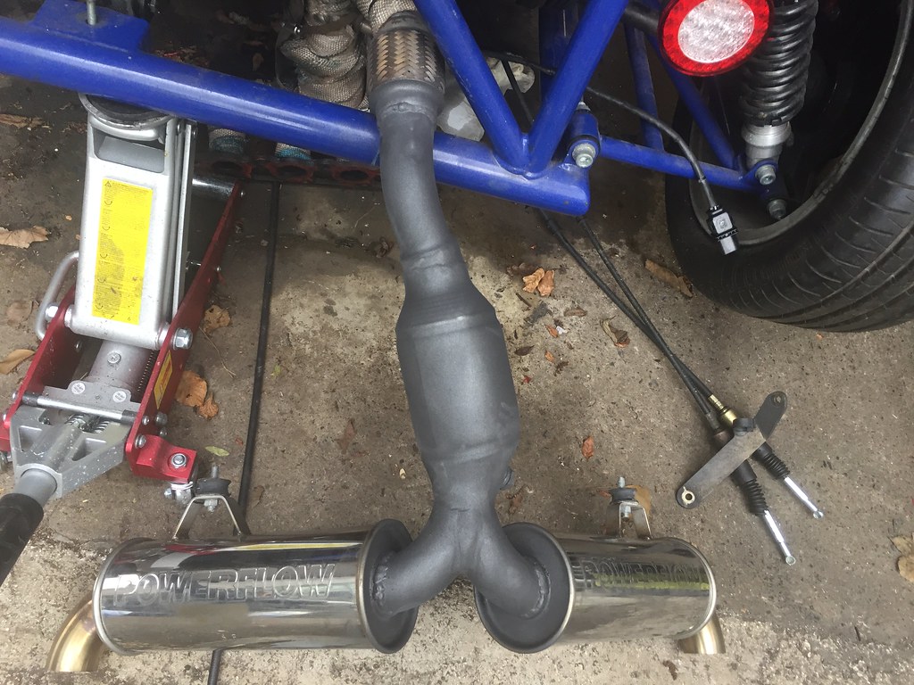 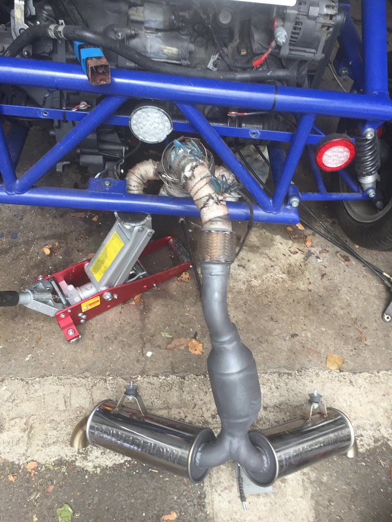 Wiring completely disconnected 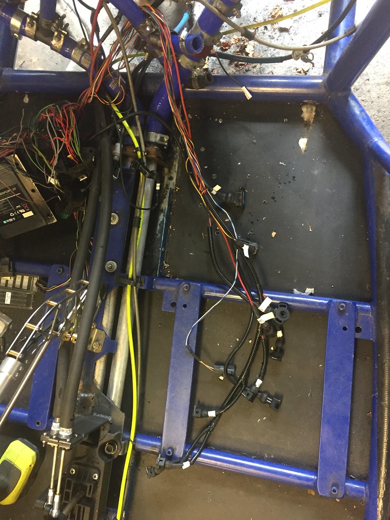 All dependencies in the car sorted, now to learn CAD. 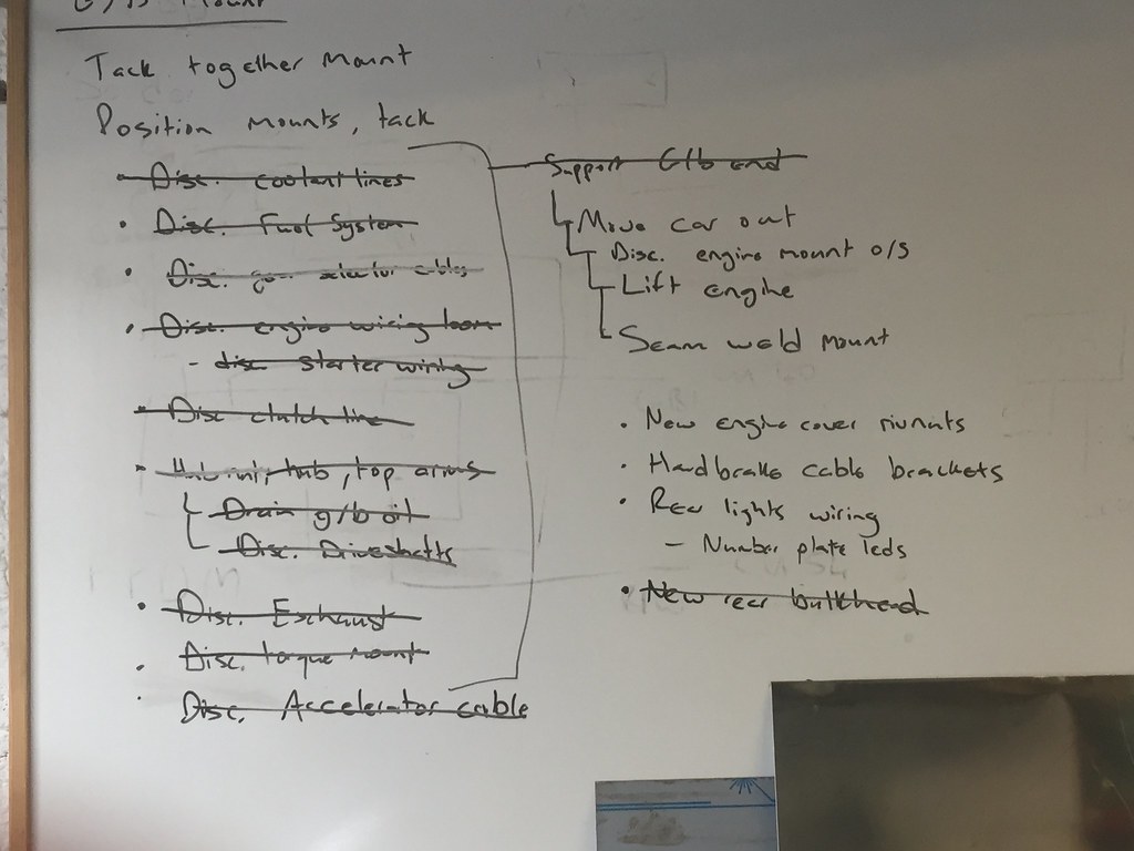 |
|
|
|
Post by casesensitive on Jan 29, 2019 8:25:12 GMT
Small jobs this past weekend, caliper is goosed, more on that thread. Bit of etch primer, paint and clearcoat on the revised gear selector 'mount' 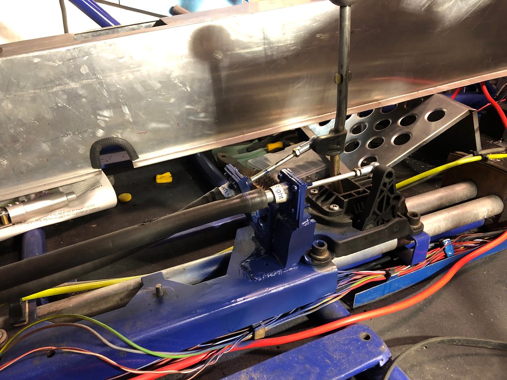 Then some convoluted tubing over the wiring, some of which dips under the cooling pipe mount in places, to allow the tunnel to fit. Feels like that could be better. At least it closes now. 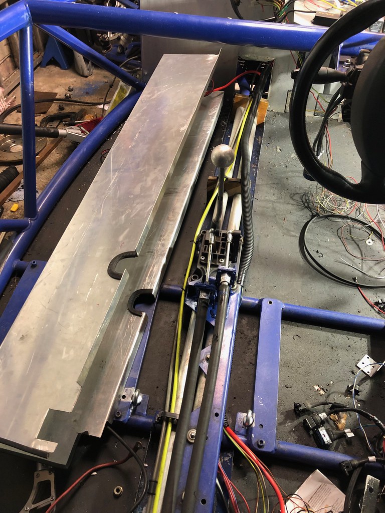 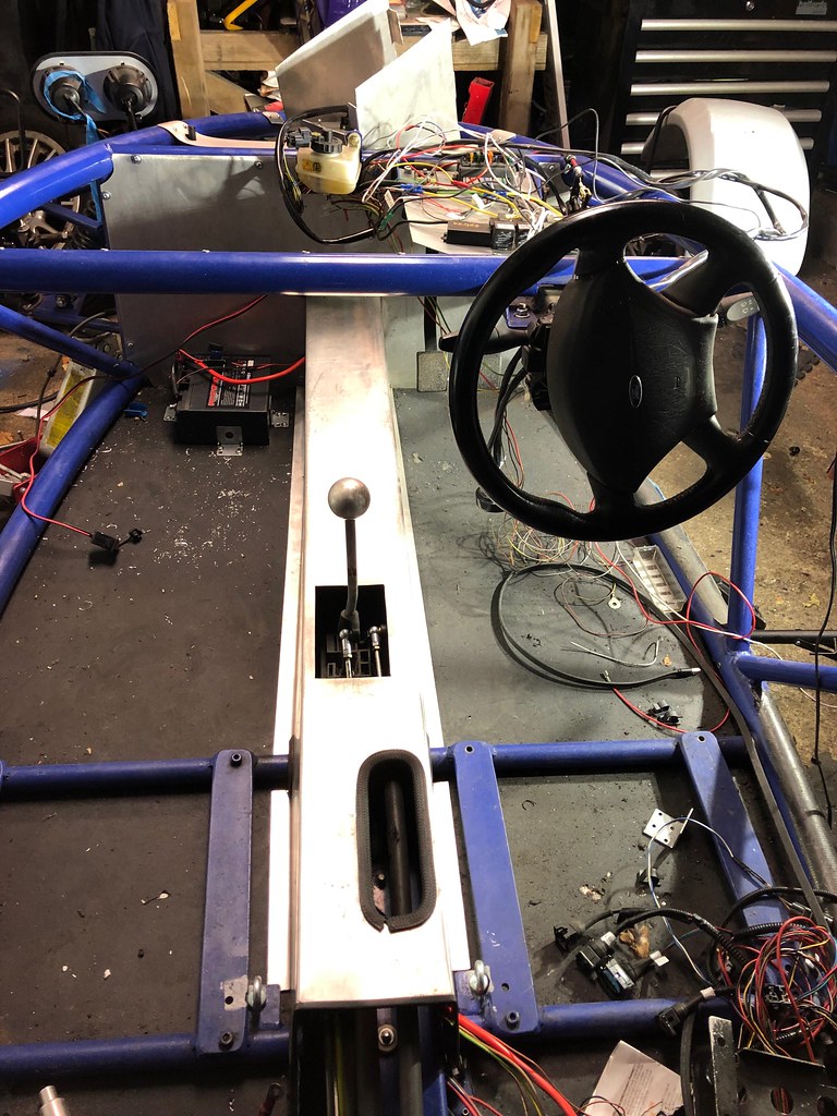 Project A4-80 continues, all SS up front now. Finding the two M10 x1.5mm thread nuts in the garage was a fun time, easily an hour spent on that. FML. 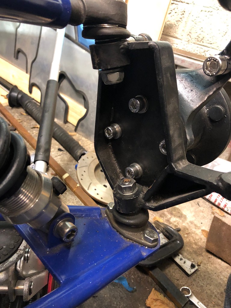 |
|
|
|
Post by casesensitive on Jun 17, 2019 7:52:43 GMT
Trying to sort two problems this weekend, red fuel and removable, sealed tank lid/ring. The existing fuel sender arm had been extended, and was an amalgam of 3 pieces of steel of different grades. I reckon the only place the red colouring could be coming from was one of the welds, likely with mild steel filler. I took 1 nice clean piece of 316L 2.4mm filler and bent it into the right shape, this is the first draft, which needed some extra bends to clear the tank edges in the installed position. 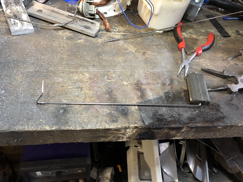 Test fit  No turning back now  Clamp and clean, wipe with acetone and chill blocks to absorb as much heat as practical  Not exactly insta-ready, but it won't leak   Gasket-maker to seal the threaded M4s and to stick down the rubber gasket ring I made 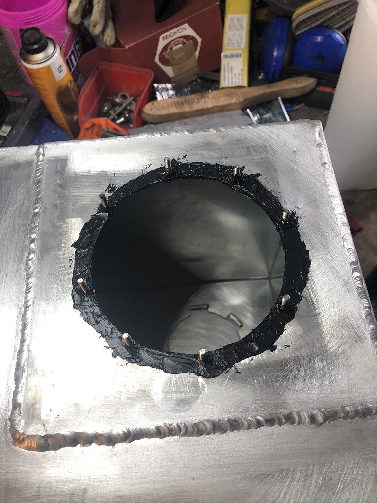   Put the red petrol back in to make sure it turned over, which it reluctantly did; battery definitely needs a new one, but that's a job for closer to the finish line. Dodgy fuel will be flushed through with nice clean stuff next weekend. Added an led in series with the fuel pump wiring, so it illuminates when the pump is being told to run, acts as a nice sense-check for ECU issues. I might do a whole board (1 injector, 1 for each side of the coil pack, fuel pump, vvt) and have a little LED diag board like MSI motherboards from the 00s. |
|
|
|
Post by casesensitive on Jul 2, 2019 13:43:51 GMT
I calibrated it a few months ago, with my Spyda, but it looks like there's a wiring issue since then. It reads full when the wires are completely disconnected, so something's got awry since Jan. I cut about half of the wires running from front to back, because they weren't routed through chassis box section, rather around it, where they'll foul the tunnel. I took the opportunity to extend a few that were a bit short, and to put bullet connectors on a few should they need to be moved again.
|
|
|
|
Post by casesensitive on Jan 30, 2022 20:03:44 GMT
Did about 90 mins in the garage during the week, tracking down fuel issue.
Test 1:
Pump wired up and very sketchily pulling fresh fuel via a short piece of hose from an old ribena bottle and into a jerry can, so the wiring and pump are good.
Test 2, same, but put the filter after the pump outlet and before the jerry can, lower pressure, but still good.
Test 3, introduced the existing, used-to-be-good fuel circuit, save for the fuel tank (don't want any of this crappy fuel going back in) there's definitely an issue between the rail and the return line, as there's little to no fuel coming back through the system and after a few seconds the least-tight clips let go giving me a lovely petrol shower. And the fuel has become orange. Tank and rail are aluminium, and the fuel filter is too, so where the hell is the rust coming from?
I'd hoped it wasn't the fuel pump, but it seems likely that it's the fuel pressure regulator, which costs even more. Going to bypass it altogether when I get a minute to confirm. There's no vacuum line going to it, but it should still limit flow to 3 bar. With the very shonky temp setup I have I can't hold the fuel in and out lines while looking at the fuel pressure gauge either, so I can't tell what it used to be.
In investigation replacing it, I note the ads from Demon Tweeks and CBS both suggest that the gauge only be used for setting up, and the outlet be bunged the rest of the time. Anyone else running a full-time analog FPR gauge?
Wonder if it got tired and died of continued use?
|
|
|
|
Post by casesensitive on May 5, 2022 9:00:59 GMT
For the lid I found some 3mm aluminium that I like, same sheet as the existing replacement 'ring' I made. I made some paper templates to scale, showing where the cutout for the weld-in wiring connector base and 12mm holes for weld-in AN fittings will go.  Used this to make an aluminium template/drilling jig out of 2.5mm. Good for centring holes, tracing around etc. Pillar drill has dropped dead due to lack of use, so I'm drilling these by hand with a little vertical guide when I remember to.  I've got a bit of 3mm mild steel plate I scrounged from a bin, and it'll be supplying the inner retaining ring, which will be cut in two pieces to go through the 'mouth'.  I'll thread the holes M5 (they're 3mm guide holes now), and 8x M5 bolts will be worked through with studs up. Arrow straight or its all for naught. Then I weld them in place so they can't rotate. I have 1mm cork gasket chaperone to keep mild and aluminium from being friends. So from top to bottom it'll go: - Nut
- nitrile / fuel proof Washer
- Aluminium lid
- Gasket
- Aluminium tank
- gasket
- steel retaining ring
- stainless steel bolt
I may need some sort of barrier grease for the stainless bolts as they pass through aluminum too, thoughts? |
|
|
|
Post by casesensitive on May 18, 2022 15:08:12 GMT
Ok, a little closer. Made some little paper templates, which got turned into 3.5mm plywood templates, screwed to the correctly-spaced (this time) holes, which will eventually be M5.    Then plasma cut my 170mm diameter retaining rings (much cleaning post cut)  Oh lawd that's ugly, my plasma work is rough as a badger's behind  Got my drill press back up and running, these need to be as vertically straight as I can manage  Holes lined up, it's time to transfer these holes to the tank. Lots of load-bearing tape holding them square. 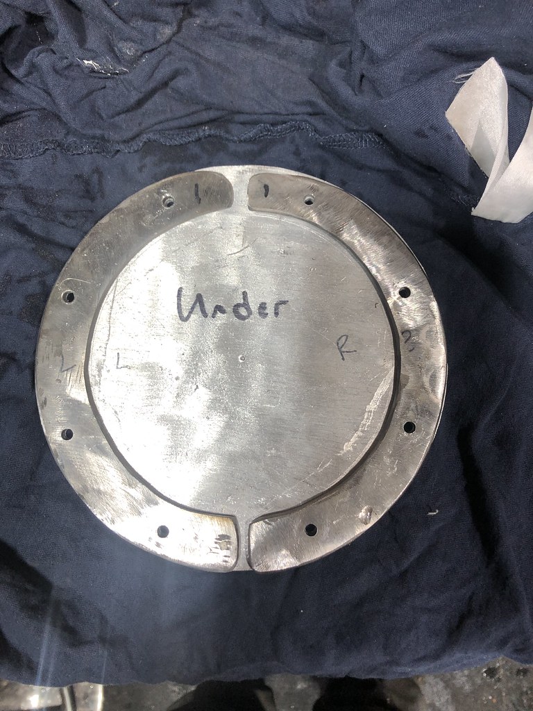  Don't have a good scrap petrol-sound fuel pump, so I put a prefilter on a bit of 8mm ID hose, and plan was to suck the cleanish fuel out of the tank with this. Buuuuut for some reason, there's no power to anything and I haven't got time to troubleshoot extensively. Battery is charged and connected, so it's likely a fuse. Not a job to be rushed with an open-to-the-air fume-filled tank in a small garage, I'll come back tomorrow.  This will be the approximate placement of my wiring grommet and weld-on AN fittings. 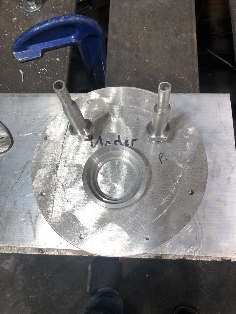 The visible topside is a lot prettier, and will get a nice 80 grit brushed finish before I start drilling or welding.  No turning back once I put that first bead down. Really going to have to think hard about the right settings for those. No pedal. Deep penetration is not vital, but pinholes are out of the question. |
|
|
|
Post by casesensitive on May 23, 2022 10:12:00 GMT
Ok, here we go. Cheapo pump (sounds like a solenoid in operation) with pre-filter, in-line fuse holder, chopped off leads from an old charger. 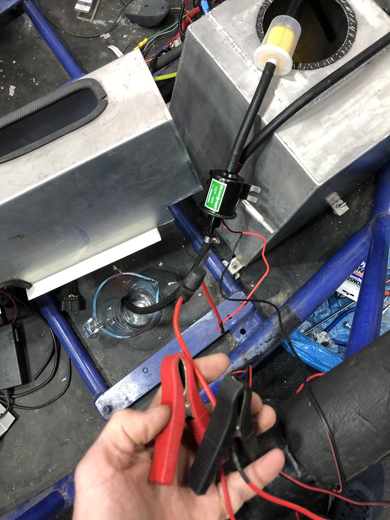 Video in operation Video in operationClean fuel  Horror show of in-tank gunk, mostly the sealant I used 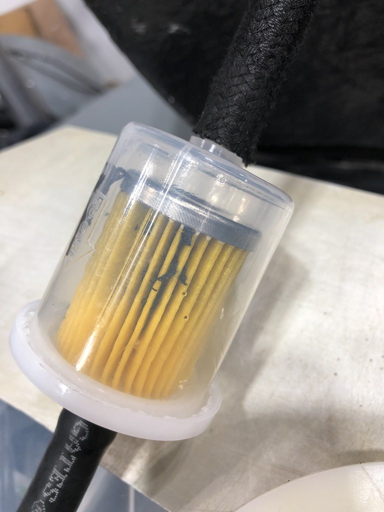 In go the retaining rings, some fettling required. Ok, a lot. 2 nuts on the threads, bit of a whack with a small hammer. 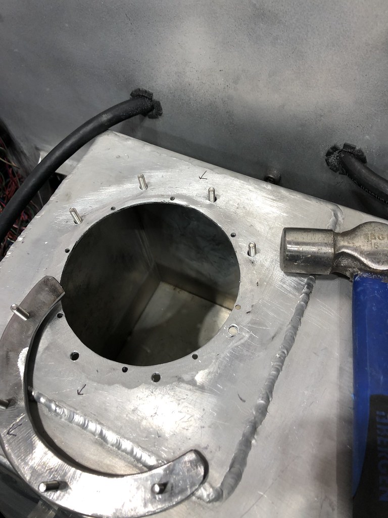 That's in fettling range now. The eagle-eyed will notice this is not the same lid.  Neat holes positioned for the AN fittings and 50mm for the weld-in wiring thingy   And a pair of 1mm cork gaskets, top one looks a bit like a Tuskan Raider.   |
|


