|
|
Post by welshy1 on Oct 27, 2013 23:04:20 GMT
Good work liking the idea with the fuel tank if I was to do another one would make my own one up routing the pipe from behind the passenger seat was a pain in the arse. Im just about finished going to rtr at the end of the year when it's iva'd will pop up to see it.
|
|
|
|
Post by gwnwar on Oct 28, 2013 4:58:43 GMT
Nice mock up work.. Looks like you should be able to get another gal or two with the tapered sides.. The extra cost now in making it is worth not walking later for gas.. And now you have a place for a can of flat fix..
|
|
|
|
Post by jgilbert on Oct 30, 2013 23:01:23 GMT
Good work liking the idea with the fuel tank if I was to do another one would make my own one up routing the pipe from behind the passenger seat was a pain in the arse. Im just about finished going to rtr at the end of the year when it's iva'd will pop up to see it. That will be great. Almost a year since you picked up the roof. Keep us posted on your build and IVA progress. |
|
|
|
Post by welshy1 on Oct 31, 2013 21:17:04 GMT
Yea forgot about that still have it on my newer mx5 been brilliant fare play, will be going to rtr either late December or early 2014 ready for spring best get my recovery truck on the road and finish the kit not much left to do.
|
|
|
|
Post by tlight on Nov 2, 2013 16:49:52 GMT
Like your seat mounting bracket idea, I did see a few people comment on drilling holes to drain away water in the even of being caught in wet weather.
|
|
|
|
Post by jgilbert on Nov 9, 2013 0:53:55 GMT
Ok, so we now have finished work on our Fuel Tank design and mounting. So after what seemed like a long time and a lot of cardboard templates here's what we have come up with. First the design. So I wanted a range of 200 miles and the design we used gives me 10.3 gallons. Design and volume calculations shown below if anyone wants to do similar.   NOTE I did change the sender mounting orientation during the fabrication and the cut the front mounting tabs down by 20mm for fuel pipe clearance. NOTE I did change the sender mounting orientation during the fabrication and the cut the front mounting tabs down by 20mm for fuel pipe clearance.So the first job was to cut the opening for the fuel sender/pump in the tank top plate. You can see in my previous posts and drawing the sender was originally mounted 'square' in the top plate. I then noticed this meant the fuel outlet and return pipes were at approximately 45 degrees when viewed from above. Rotating the sender through approximately 45 degrees meant that the pipes were square. This gave a better line for the fuel pipes to follow. Next photo shows what I mean,  Top plate drilled and Rivneted.  Whilst the tank was away being welded up I made a simple bracket for the fuel filter and hose clamps and earthing point. Nice fun job.  The next step was an additional fuel pipe clamp position on the sub frame. Note I intend to cover the hose with protective sleeve where it travels up through the sub frame.  In order to support the tank I cut and welded 4 studs onto two sections of 20mm box section that run across the rear chassis as shown below (LHS side bar is back to front in the photo) 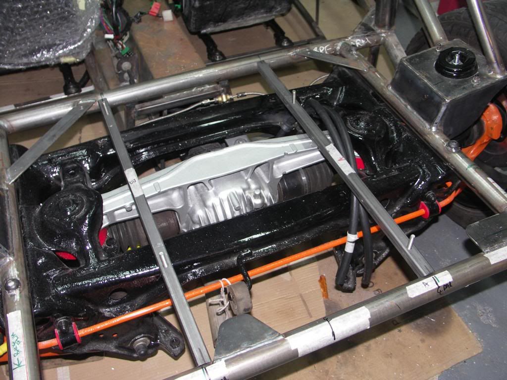 Then the big moment, I got a call to say the tank was finished.   To form a 'floor' for the rear space and protect the underside of the tank (this also gives a nice 'clean' finish when viewed from under the car and will hopefully address any IVA fuel leaking onto the exhaust concerns) I cut a 1.5mm piece of Ally to size and bend the front facing edge to give me a location for the fibreglass rear bodywork. Two strips of rubber then positioned above the box section to minimise vibration transfer.  Then a matter of mounting the tank into position and connecting up the hoses (top two hose clips missing).   Hose detail.  and finally with the body work in place. Nice usable space in front of the tank for tools and wet weather gear etc. Only job left is to cut an opening for the filler and connect this up. Any comments on anything I've missed appreciated.   |
|
|
|
Post by gwnwar on Nov 9, 2013 5:00:13 GMT
Don't see a vent on the tank.. What filler cap do you plan on using.. Very nice clean design.. like it..
|
|
|
|
Post by red5 on Nov 9, 2013 8:45:11 GMT
nice work john - very tidy
Are you going to shield off the filter from the compartment ,purely to prevent anything snagging on the clips? - Im not sure what the IVA would be like for contactable (i.e 3mm radius) items in there also etc
|
|
|
|
Post by jgilbert on Nov 9, 2013 20:10:54 GMT
Don't see a vent on the tank.. What filler cap do you plan on using.. Very nice clean design.. like it.. Hi Gwnwar, yes have a vented aero cap on order as I thought that was the easiest solution. |
|
|
|
Post by jgilbert on Nov 9, 2013 20:14:44 GMT
nice work john - very tidy Are you going to shield off the filter from the compartment ,purely to prevent anything snagging on the clips? - Im not sure what the IVA would be like for contactable (i.e 3mm radius) items in there also etc Hi Red5, we intend putting a 'door' on the bulkhead so I didn't think the space inside the 'boot' would need minimum radius. It's a good point and an easy fit, thanks for the suggestion. |
|
|
|
Post by jgilbert on Nov 11, 2013 23:16:33 GMT
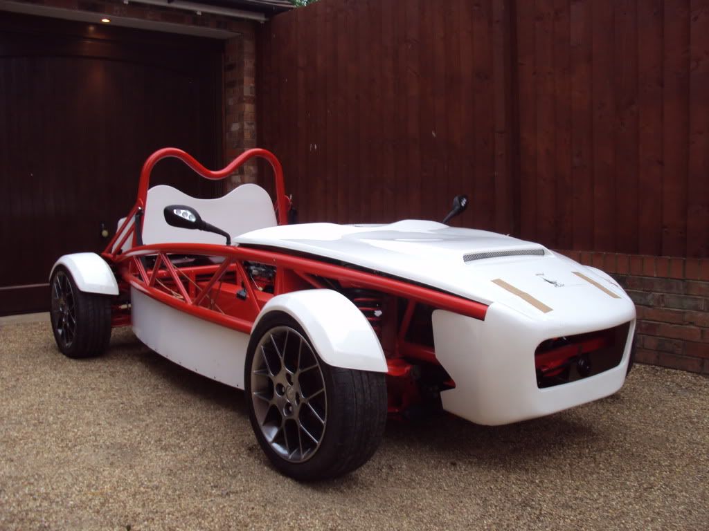
Everyone seems busy at the moment with their builds. Good inspiration. With the fuel tank done albeit still to add the filler cap (on order). It was time to move the car out of the garage and turn it around to work on the front. Landmark moment, wheels turning for the first time since we wheeled the PPF into the garage about this time last year. Couldn't resist a photo.  Back in the garage we started looking at the bonnet position and none cone. Bonnet needed a trim around the instrument pod. Simple enough and it finishes very nicely with my dash.  The edging I'm using is U shaped Rubber, this is thinner that the standard MEV plastic trim, as the edges are facing downwards I'm hoping it shouldn't cause an IVA problem. Any Comments  Close up of the trim.  With the bonnet on, it was time to fit the nose cose. Had to grind the leading edges of the top frame tubes in order for the nose to sit square. A time consuming job, a little bit of sanding of the nose edge where it meets the bonnet but no real issues. Found I had to prop the near side bottom of the nose out from the rad in order to have the same gap between the chassis and the inside face of the nose side vents (see use of wood in photo).  What I would recommend is fitting the nose without the mesh fitted. Without it it allows you to get inside the cose use the chassis as a reference datum to get everything square. We then used a smaller section of Rubber U trim on the back edge of the nose. Again I can't see this being a major IVA issue ?? We will use the larger MEV edge trim on the sides of the nose. See below.  Three 6mm fixings in each side. These will be changed out to Black dome head allen screws. Used roofing bolts for tonight.  Job done. Just need Aero catches now. Plan is to go for 3. One either side and one in the front middle.  Next job is headlight mountings and front indicators. |
|
|
|
Post by tlight on Nov 12, 2013 6:36:54 GMT
Hi,
Got a link for the u shaped trim ?
Tim
|
|
|
|
Post by red5 on Nov 12, 2013 21:01:10 GMT
John - I cant think of any IVA snags with the radius on that u shape trim.
I think the reason for the supplied trim being recommended on the bonnet and nose trim is to absorb some of the vibration from the fibreglass onto the powder coat , which ( and I cant remember where I saw it)has a habit of wearing holes in it.
|
|
|
|
Post by jgilbert on Nov 12, 2013 21:48:19 GMT
Hi, Got a link for the u shaped trim ? Tim Tim, Yes Ebay special, I plan to glue using a very small quantity of black PU adhesive in the bottom of the channel. |
|
|
|
Post by tlight on Nov 13, 2013 11:48:22 GMT
Sorry, can you add eBay link ?
Tim
|
|